2002 Hyundai Getz lights
[x] Cancel search: lightsPage 179 of 428

6- 6 DO-IT-YOURSELF MAINTENANCE
G020A01A-AAT GENERAL CHECKS Engine Compartment The following should be checked regu-larly:
o Engine oil level and condition
o Transaxle fluid level and condition
o Brake fluid level
o Clutch fluid level
o Engine coolant level
o Windshield washer fluid level
o Accessory drive belt condition
o Engine coolant hose condition
o Fluid leaks (on or below compo-
nents)
o Power steering fluid level
o Battery condition G020C01A-AAT Vehicle Interior The following should be checked each time when the vehicle is driven:
o Lights operation
o Windshield wiper operation
o Horn operation
o Defroster, heater system operation
(and air conditioning, if installed)
o Steering operation and condition
o Mirror condition and operation
o Turn signal operation
o Accelerator pedal operation
o Brake operation, including parking brake
o Manual transaxle operation, includ- ing clutch operation
o Automatic transaxle operation, in- cluding "Park" mechanism opera-tion
o Seat control condition and opera- tion
o Seat belt condition and operation
o Sunvisor operation If you notice anything that does not operate correctly or appears to befunctioning incorrectly, inspect it care- fully and seek assistance from your Hyundai dealer if service is needed.
G020B01A-AAT Vehicle Exterior The following should be checked monthly:
o Overall appearance and condition
o Wheel condition and wheel nut
torgue
o Air filter condition
o Exhaust system condition
o Light condition and operation
o Windshield glass condition
o Wiper blade condition
o Paint condition and body corrosion
o Fluid leaks
o Door and hood lock condition
o Tire pressure and condition (including spare tire)
Page 200 of 428

DO-IT-YOURSELF MAINTENANCE 6- 27
CAUTION:
When replacing a fusible link, never use anything but a new fusible link with the same or lower amperage rating. Never use a piece of wire ora higher-rated fusible link. This could result in serious damage and create a fire hazard.!
4. Replace the blown fuse by pressing a new fuse of the same rating into place. The fuse should be a snug fit. If it is not, have the fuse clip repairedor replaced by a Hyundai dealer. If you do not have a spare fuse, you may be able to borrow a fuse of thesame or lower rating from an acces-
G200B02A-AAT Replacing Accessory Fuse The fuse box for the lights and other electrical accessories will be found low on the dashboard on the driver's side.Inside the box you will find a list show- ing the circuits protected by each fuse. If any of your car's lights or otherelectrical accessories stop working, a blown fuse could be the reason. If the fuse has burned out, you will see thatthe metal strip inside the fuse has burned through. If you suspect a blown fuse, follow this procedure:
HTB180
1. Turn off the ignition and all other
switches.
2. Open the fuse box and examine each fuse. Remove each fuse by pulling it toward you (a small "fuse puller" tool is contained in the fusebox to simplify this operation).
3. Be sure to check all other fuses
even if you find one that appears tohave burned out.
HTB223
Page 204 of 428

DO-IT-YOURSELF MAINTENANCE 6- 31
1. Remove the engine cover.
2. Disconnect the air intake hose from
air cleaner cover.
3. Loosen the drain plug at the bottom of the fuel filter.
4. Tighten the drain plug when water no longer comes out.
5. Check to be sure that the warning
lamp illuminates when the ignition key is turned to "ON", and that it goes off when the engine is started. If in doubt, consult your nearestauthorized HYUNDAI dealer.
NOTE: It is recommended that water accu- mulated in the fuel filter should beremoved by an authorized Hyundai dealer. G300B01FC
WARNING:
Be sure to carefully wipe away anywater drained out in this manner, because the fuel mixed in the watermight be ignited and result in a fire.
!
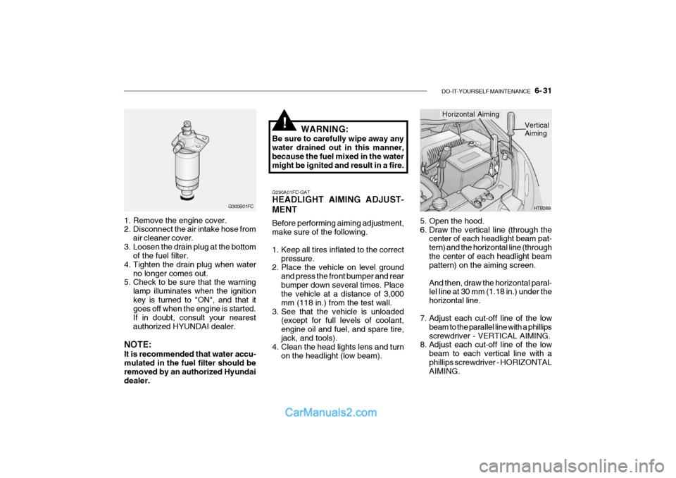
5. Open the hood.
6. Draw the vertical line (through the center of each headlight beam pat-tern) and the horizontal line (throughthe center of each headlight beam pattern) on the aiming screen. And then, draw the horizontal paral- lel line at 30 mm (1.18 in.) under the horizontal line.
7. Adjust each cut-off line of the low beam to the parallel line with a phillipsscrewdriver - VERTICAL AIMING.
8. Adjust each cut-off line of the low
beam to each vertical line with aphillips screwdriver - HORIZONTAL AIMING. HTB269
Horizontal Aiming
Vertical Aiming
G290A01FC-GAT HEADLIGHT AIMING ADJUST- MENT Before performing aiming adjustment, make sure of the following.
1. Keep all tires inflated to the correct pressure.
2. Place the vehicle on level ground
and press the front bumper and rear bumper down several times. Place the vehicle at a distance of 3,000 mm (118 in.) from the test wall.
3. See that the vehicle is unloaded (except for full levels of coolant,engine oil and fuel, and spare tire,jack, and tools).
4. Clean the head lights lens and turn
on the headlight (low beam).
Page 205 of 428

6- 32 DO-IT-YOURSELF MAINTENANCE
If the vehicle has had front body repair and the headlight assembly has been replaced, the headlight aiming should be checked using the aiming screen asshown in the illustration. Turn on the headlight switch. (Low Beam Position)
1. Adjust headlights so that main axis
of light is parallel to center line of the body and is aligned with point "P"shown in the illustration.
2. Dotted lines in the illustration show
the center of headlights.
G290B01TB-GAT Adjustment After Headlight As- sembly Replacement
SPECIFICATIONS: "H" Horizontal center line of headlightsfrom ground. : 656 mm (26.8 in.) "W" Distance between each headlight center.: 1,100 mm (43.3 in.) "L" Distance between the headlights and the wall that the lights are tested against.: 3,000 mm (118 in.).
G290B01L
LW
H
H Cut-off line
Ground line
"P"
Horizontal line15mm (0.59in.)
30mm (1.18 in.) Vertical line G270A01TB-GAT REPLACEMENT OF BULBS Headlight Bulb Before attempting to replace a head- light bulb, be sure the switch is turned to the "OFF" position.The next paragraph shows how to reach headlight bulbs so they may be changed. Be sure to replace theburned-out bulb with one of the same number and wattage rating.
CAUTION:
Keep the lamps out of contact with petroleum product, such as oil,gasoline, etc.
!
Page 233 of 428

10- 6 INDEX
V Vehicle Identification Number ..................................... 8-2
W Warning Lights .......................................................... 1-44
Windshield Wiper and Washer................................. 1-54
Windshield Wiper Blades ................... ....................... 6-17
Winter Driving ........................................................... 2-15
Page 244 of 428

YOUR VEHICLE AT A GLANCE
B255A01TB-GAT INDICATOR SYMBOLS ON THE INSTRUMENT PANEL * A detail explanations of these items will be found on page 1-37
SRS (Airbag) Service Reminder Indicator ABS Service Reminder Indicator Turn Signal Indicator Lights High Beam Indicator Light Oil Pressure Warning Light Parking Brake/Brake Level Warning Light Charging System Warning Light Tail Gate Open Warning LightDoor Ajar Warning Light and Chime
Low Fuel Level Warning Light Malfunction Indicator Light Seat Belt Reminder Light
O/D OFF Indicator (Automatic transaxle only)
Electric Power Steering System (EPS)Warning Light
Diesel Pre-heat Indicator Light (Diesel only)
Fuel Filter Warning Light (Diesel only)
Immobilizer Indicator
Page 245 of 428

1. FEATURES OF YOUR HYUNDAI
Fuel Recommendations ................................................................... 1-2
Running In ........................................................................................ 1-3
Immobilizer system .......................................................................... 1-4
Door locks (Theft-alarm system) ..................................................... 1-5
Power windows .............................................................................. 1-10
Seat ................................................................................................ 1-11
Seat Belt ......................................................................................... 1-16
Child restraint system .................................................................... 1-21
Supplemental restraint (AIRBAG) system ..................................... 1-29
Instrument cluster and indicator lights ............................................ 1-35
Warning Light and Indicator ............................................................ 1-37Trip computer................................................................................. 1-44
Multi-Function Light Switch ............................................................ 1-46
Windshield wiper/Washer Switch ................................................... 1-48
Sunroof .......... ................................................................................. 1-53
Mirror .............................................................................................. 1-57
Bonnet Release .............................................................................. 1-60How to use luggage Room ............................................................. 1-63
Heating and cooling control ............................................................ 1-68Stereo sound system ..................................................................... 1-77
Antenna .......................................................................................... 1-81
1
Page 251 of 428

FEATURES OF YOUR HYUNDAI 1- 7
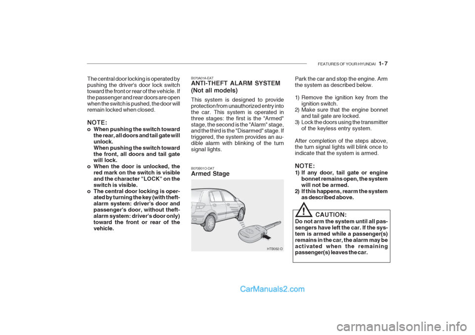
B070A01A-EAT ANTI-THEFT ALARM SYSTEM (Not all models) This system is designed to provide protection from unauthorized entry intothe car. This system is operated inthree stages: the first is the "Armed"stage, the second is the "Alarm" stage, and the third is the "Disarmed" stage. If triggered, the system provides an au-dible alarm with blinking of the turnsignal lights.
The central door locking is operated bypushing the driver's door lock switchtoward the front or rear of the vehicle. Ifthe passenger and rear doors are openwhen the switch is pushed, the door will remain locked when closed. NOTE:
o When pushing the switch toward
the rear, all doors and tail gate will unlock.When pushing the switch towardthe front, all doors and tail gate will lock.
o When the door is unlocked, the red mark on the switch is visible and the character "LOCK" on theswitch is visible.
o The central door locking is oper- ated by turning the key (with theft-alarm system: driver's door andpassenger's door, without theft-alarm system: driver's door only)toward the front or rear of thevehicle. Park the car and stop the engine. Armthe system as described below.
1) Remove the ignition key from the
ignition switch.
2) Make sure that the engine bonnet
and tail gate are locked.
3) Lock the doors using the transmitter
of the keyless entry system.
After completion of the steps above, the turn signal lights will blink once to indicate that the system is armed. NOTE:
1) If any door, tail gate or engine bonnet remains open, the system will not be armed.
2) If this happens, rearm the system as described above.
CAUTION:
Do not arm the system until all pas-sengers have left the car. If the sys-tem is armed while a passenger(s)remains in the car, the alarm may beactivated when the remaining passenger(s) leaves the car.
!
HTB052-D
B070B01O-DAT Armed Stage