2002 Hyundai Getz fuel
[x] Cancel search: fuelPage 380 of 428

6- 6 DO-IT-YOURSELF MAINTENANCE
SG020B1-E DAILY OPERATING CHECKS The following items should be checked on a daily basis or whenever the vehicleis refuelled, whichever occurs sooner.
o Engine oil level.
o Engine coolant level.
o Power steering fluid level.
o Brake fluid level.
o Windscreen washer fluid level.
o Battery condition.
o Tyre condition and pressures.
o Operation and cleanliness of all light-
ing equipment.
o Windscreen wiper and washer opera- tion.
o Horn operation.
o Warning light operation.
o Adjustment and cleanliness of mir- rors.
o Seat and seat belt adjustment and operation.
o Fluid leakage. The vehicle must not be driven if the daily operating checks indicate that any item of equipment related to thesafety or roadworthiness of the vehicle is not functioning correctly. G030B02A-EAT Recommended Oil
1. Petrol engine A multi grade oil having a specification which meets A.P.I. specification of SGor above is recommended. The oil vis- cosity should be selected according to the operating environment of the engineby means of the table shown in the illustration. The engine oil recommen- dations are complete in themselvesand the use of additives is neither required nor recommended. The use of engine oil additives may result in invali-dation of the vehicle warranty.
G030A01FC-EAT ENGINE OIL The correct engine oil level is of para- mount importance. An excessively highor low oil level may result in irreparable damage being sustained by the engine. The engine oil level must be checkedon a daily basis, whenever the vehicle is refuelled or before starting a long trip, whichever occurs sooner.In addition, it is imperative that only an approved grade and specification of oil is used to avoid the possibility of seri-ous engine damage and premature wear. The use of "budget price" oil is a false economy that must be avoided if themaximum reliability and useful life is to be obtained from the vehicle.
G030B01L
Page 391 of 428

DO-IT-YOURSELF MAINTENANCE 6- 17
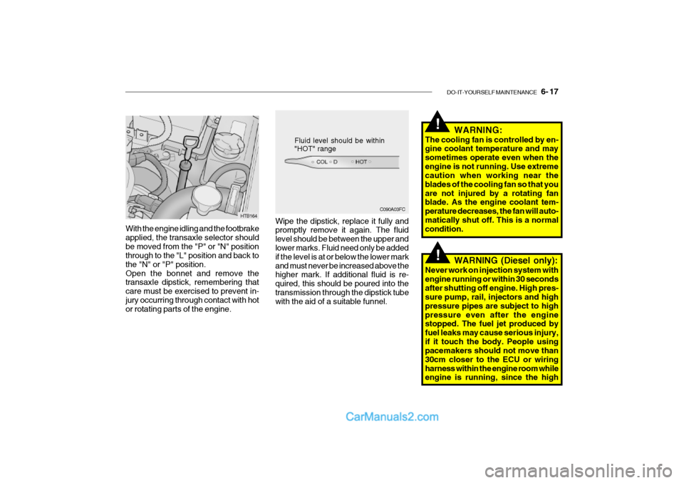
With the engine idling and the footbrake applied, the transaxle selector shouldbe moved from the "P" or "N" position through to the "L" position and back to the "N" or "P" position.Open the bonnet and remove the transaxle dipstick, remembering that care must be exercised to prevent in-jury occurring through contact with hot or rotating parts of the engine.
C090A03FC
Fluid level should be within "HOT" range
HTB164 Wipe the dipstick, replace it fully and promptly remove it again. The fluid level should be between the upper and lower marks. Fluid need only be added if the level is at or below the lower markand must never be increased above the higher mark. If additional fluid is re- quired, this should be poured into thetransmission through the dipstick tube with the aid of a suitable funnel. WARNING:
The cooling fan is controlled by en-gine coolant temperature and may sometimes operate even when theengine is not running. Use extreme caution when working near the blades of the cooling fan so that youare not injured by a rotating fan blade. As the engine coolant tem- perature decreases, the fan will auto-matically shut off. This is a normal condition.
!
!WARNING (Diesel only):
Never work on injection system with engine running or within 30 secondsafter shutting off engine. High pres- sure pump, rail, injectors and high pressure pipes are subject to highpressure even after the engine stopped. The fuel jet produced by fuel leaks may cause serious injury,if it touch the body. People using pacemakers should not move than 30cm closer to the ECU or wiringharness within the engine room while engine is running, since the high
Page 400 of 428

6- 26 DO-IT-YOURSELF MAINTENANCE
HTB287
SG230B1-E POWER STEERING HOSES Power steering hoses should be checked for damage, deterioration andleakage at each service.
steering fluid level is between the "MAX" and "MIN" level markings on the fluid reservoir. NOTE: Grinding noise from power steering pump may be heard immediatelyafter the engine is started in extremely
cold condition (below -4°F). If the noise stops during warm up, there isno abnormal function in the system. This is due to a power steering fluid characteristic in extremely cold con-ditions. FLUID RECOMMENDATION Only automatic transmission fluid meet- ing the specification of PSF-3 shouldbe used in the power steering system.
G300A01TB-GAT REMOVAL OF WATER FROM THE FUEL FILTER(DIESEL ENGINE) If the fuel filter warning lamp illuminates during driving, it indicates that waterhas accumulated in the fuel filter. If this occurs, remove the water as described.
SG230A1-E POWER STEERING FLUID LEVEL The power steering fluid level should be checked daily.To check the power steering fluid level, be sure the ignition is "OFF", then check to make certain that the power
HTB163
Page 401 of 428

DO-IT-YOURSELF MAINTENANCE 6- 27
5. Open the hood.
6. Draw the vertical line (through the
center of each headlight beam pat-tern) and the horizontal line (throughthe center of each headlight beam pattern) on the aiming screen. And then, draw the horizontal paral- lel line at 1.18 in. (30 mm ) under the horizontal line.
7. Adjust each cut-off line of the low beam to the parallel line with a phillipsscrewdriver - VERTICAL AIMING.
8. Adjust each cut-off line of the low
beam to each vertical line with aphillips screwdriver - HORIZONTAL AIMING. HTB269
Horizontal Aiming
Vertical Aiming
G290A01FC-EAT HEADLIGHT AIMING ADJUST- MENT Before performing aiming adjustment, make sure of the following.
1. Keep all tires inflated to the correct pressure.
2. Place the vehicle on level ground
and press the front bumper and rear bumper down several times. Place the vehicle at a distance of 118 in. (3,000 mm) from the test wall.
3. See that the vehicle is unloaded (except for full levels of coolant,engine oil and fuel, and spare tire,jack, and tools).
4. Clean the head lights lens and turn
on the headlight (low beam). WARNING:
Be sure to carefully wipe away anywater drained out in this manner,because the fuel mixed in the water might be ignited and result in a fire.!
1. Remove the engine cover.
2. Disconnect the air intake hose from air cleaner cover.
3. Loosen the drain plug at the bottom
of the fuel filter.
4. Tighten the drain plug when water no longer comes out.
5. Check to be sure that the warning
lamp illuminates when the ignition key is turned to "ON", and that it goes off when the engine is started.If in doubt, consult your nearest au- thorized HYUNDAI dealer.
G300B01FC
Page 408 of 428

6- 34 DO-IT-YOURSELF MAINTENANCE
G200C01TB-GAT FUSE PANEL DESCRIPTION Engine Compartment
HTB261-EPROTECTED COMPONENTS
Ignition Switch
Ignition Switch, Start Relay
Fuel pump, Alternator, ECM
Auto Fuel Cut Switch
Radiator Fan
Headlight, Defogger RelayABSECMA/CON, Fuel PumpInjectorA/Conditioner
HornABSABS
Blower, Blower Motor
Power Window
Electronic power steering AlternatorSpare Fuse Spare FuseSpare Fuse
FUSE RATING
30A30A30A20A30A50A10A10A10A15A10A10A20A40A30A30A50A 15A 10A10A
DESCRIPTION
IGN 2IGN 1ECU
F/PUMP RAD
BATT ABS
ECU
SNSR INJ
A/CON HORN ABS1ABS2 BLW
P/WDW EPS
BATT( ) SPARE
SPARE
SPARE
NOTE:
Not all fuse panel descriptions in this manual may be applicable to your vehicle. It is accurate at the time of printing. When you inspect the fuse box on your vehicle, refer to the fuse box label.
1.1L 1.3/1.6L 100A120A
Page 411 of 428

7- 2 EMISSION CONTROL SYSTEMS
SH010A1-E EMISSION CONTROL SYSTEMS (Not all models) Depending upon the market for which the vehicle is destined, the emissioncontrol system will comprise one or more of the following emission con- trol devices. 1) Crankcase emission control sys-
tem
2) Evaporative emission control sys-
tem
z3) Exhaust emission control systemIn order that the proper functioning of the emission control systems may be ensured, it is recommended that the vehicle is inspected and maintainedby an authorized Hyundai dealer in accordance with the maintenance schedule in this manual. SH010B1-E
1. CRANKCASE EMISSION
CONTROLSYSTEM
The positive crankcase ventilation
system is employed to prevent airpollution caused by blow-by gasesbeing emitted from the crankcase by introducing fresh air to the crankcase through the air cleaner where thismixes with blow-by gases and then passes through the PCV valve into the intake manifold from where it sub-sequently enters the combustion chamber and is burned.
SH010C1-E
2. EVAPORATIVE EMISSION
CONTROL SYSTEM
The Evaporative Emission Control
System is designed to prevent fuel vapours from escaping into the atmo- sphere through the fuel tank ventila- tion system.
Whilst the engine is not running, fuel
vapours generated inside the fuel tankare absorbed and stored in a char-coal canister. When the engine is started, the vapours stored in the canister are drawn into the induction SH010D1-E
3. EXHAUST EMISSION CON
TROL SYSTEM
The exhaust emission control system
is a highly effective system whichcontrols exhaust emission while main- taining good vehicle performance.
system through the purge control so-lenoid valve and are subsequently burned.
The purge control solenoid valve is
controlled by the ECU; when the en-gine coolant temperature is low or the engine is idling, the purge control valve is closed and fuel vapours re-main stored in the canister. Under normal running conditions when the engine is warm, the valve opens andthe vapours are drawn into the inlet tract and subsequently burned in the combustion chamber.
Page 412 of 428

EMISSION CONTROL SYSTEMS 7- 3
SH020A1-E
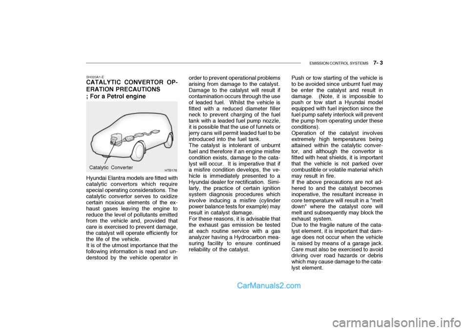
CATALYTIC CONVERTOR OP- ERATION PRECAUTIONS ; For a Petrol engine
Hyundai Elantra models are fitted with
catalytic convertors which require special operating considerations. Thecatalytic convertor serves to oxidize certain noxious elements of the ex- haust gases leaving the engine toreduce the level of pollutants emitted from the vehicle and, provided that care is exercised to prevent damage,the catalyst will operate efficiently for the life of the vehicle.
It is of the utmost importance that the
following information is read and un-derstood by the vehicle operator in
HTB178Catalytic Converter order to prevent operational problems arising from damage to the catalyst.
Damage to the catalyst will result if
contamination occurs through the use of leaded fuel. Whilst the vehicle isfitted with a reduced diameter filler neck to prevent charging of the fuel tank with a leaded fuel pump nozzle,it is possible that the use of funnels or jerry cans will permit leaded fuel to be introduced into the fuel tank.
The catalyst is intolerant of unburnt
fuel and therefore if an engine misfirecondition exists, damage to the cata-lyst will occur. It is imperative that if a misfire condition develops, the ve- hicle is immediately presented to aHyundai dealer for rectification. Simi- larly, the practice of certain ignition system diagnosis procedures whichinvolve inducing a misfire (cylinder power balance tests for example) may result in catalyst damage.
For these reasons, it is advisable that
the exhaust gas emission be testedat each routine service with a gas analyzer having a Hydrocarbon mea- suring facility to ensure continuedreliability of the catalyst. Push or tow starting of the vehicle is to be avoided since unburnt fuel may be enter the catalyst and result indamage. (Note, it is impossible to push or tow start a Hyundai model equipped with fuel injection since thefuel pump safety interlock will prevent the pump from operating under these conditions).Operation of the catalyst involvesextremely high temperatures beingattained within the catalytic conver- tor, and although the convertor is fitted with heat shields, it is importantthat the vehicle is not parked over combustible or volatile material which may result in fire. If the above precautions are not ad- hered to and the catalyst becomes inoperative, the resultant increase incore temperature will result in a "melt down" where the catalyst core will melt and subsequently may block theexhaust system.Due to the fragile nature of the cata-lyst element, it is important that dam- age does not occur when the vehicle is raised by means of a garage jack.Care must also be exercised to avoid driving over road hazards or debris which may cause damage to the cata-lyst element.
Page 421 of 428

9- 2 VEHICLE SPECIFICATIONS
1.3 L
1.6 L
Type Wheel free playRack stroke Oil pump type 150 (3,810) 65.6(1,665) 58.7(1,490) 96.7(2,455)57.1(1,450) 56.7(1,440)
Overall length Overall width Overall height (unladen) Wheel baseWheel tread J030A02TB-EAT TYRE1.1 L
13.5V,70A
Dual hydraulic with brake booster Ventilated disc DrumCable
J010A01TB-EAT MEASUREMENT
J060A01TB-DAT FUEL SYSTEM
Rack and pinion 0 ~ 1.18 in. (0 ~ 30 mm) 5.20 in. (132 mm) 5.5 in. (140 mm) Vane type
165/65R14 175/65R14, 185/55R15
StandardOption
Front Rear
mm (in.)
J020A01TB-EAT POWER STEERING
Fuel tank Capacity Litre
45 Imp.gal
9.9
J040A02TB-EAT ELECTRICAL
Item Battery Alternator
J050A01FC-GAT BRAKE Type Front brake typeRear brake type Parking brake
J035A02TB-EAT SPARE TYRE
Temporary tyre (T 150/70 D14) Full size
1.1L 1.3/1.5/1.6L
DIESEL
1.5 L
60AH
12V, 90APETROL
Manual Power 13.5V, 90A
45AH