Page 22 of 1139

ItemM€asurementOualificationStandard or NewService LimitParking brake
lever
Distance traveled when lever pulled
with 196 N (20 kgf, 44 lbs) ol force
7 8 clicks
Brake pedalPedal height (carpet removed)184 mm (7 4/16 in.)
Free play0.4 3.0 mm (0 016 0 '118 in.)Master cylinderPiston-to-pushrod clearance0 0.4 mm (0 0.02 in.)Erake discThicknessFront21.0 mm (0.83 in.)19.00 mm (0.75 in.)
Rear9.0 mm {0.35 in.)8-0 mm (0.31 in.iRunoutFront0.10 mm (0.004 in.)
Rear0.10 mm (0.004 in.)ParallelismFront and rear0.015 mm (0.0006 in.)Brake padsThicknessFront10.0 mm (0.39 in.)1.6 mm (0.06 in.)
llear9.0 mm {0.35 in.)1.6 mm (0.06 in.)
Standards and Service Limits
Brakes
a
e-o
Air Gonditionin
ItemMoasurementOualilicationStandard or New Service LimitRefrige.antTvpeHFC 134 a (B-134 a)
Capacity of system500 550 g 117.6 19.4 oz)Refrigerant oilTypeSP 1O
(P/N 38897-P13-A01AH or 38899-P13-A01 )Capacity ofcomponentsCondenser25 m0, 15/6 fl ozl
Evaporator45 mA 11 1/2 fl ozt
Each line and
hose
10 m0 (1/3 fl or)
Compressor130 150 m014 1/3 5floz)CompressorStarter coil resistanceAt 68"F (20"C)3.05 3.35 0Pulley-to-pressure plate clearance0.35 0.6 mm (0.014 0.024 in.)Drive beltAuto tensioner lneeds no adjustment)
2-10
q
Page 24 of 1139

cont'
ItemMeasuremeniOualificationSpecilicationSTEERINGTypeElectric, Power assisted rack and pinion
Overall ratio15.1Turns,lock to-lock
Steering wheel diameter360 mm (14.2 in)SUSPENSIONTypeIndependent srrul with stabiliTer. coil springRearDouble wishboneShock absorberFrontTelescopic, hydraulic. nitrogen gas-frlled
RearTelescopic, hydraulic, nitrogen gas,filledWHEEL
ALIGNMENT
CamberFront0"00'
Bear0.45'
CasterFront1'33'TotaltoeFront0 mm (0 in.)
RearIn 2 mm (1/16 in.)BRAKESType of service brakeFrontPowerassisted self-adjusling ventilated disc
BearPower-assisted self-adjusting solid discType of parking brakeMechanical actuating, rear wheelsPad friction surface areaFront45 cm'(7.0 sq in.)x2
Rear28 cm'(4.3 sq in.) x 2TIRESSize offront and reartiresPl95/60 815 88VSize o{ spare tireT125r0 D15 95MAIR
CONDITIONING
CompressorTypeScroll
Number of
cylinders
Capacity85.7 m015.23 cu in.)/rev.
Maximum speed12,000 rpm
Lubricant capacity130 m0 {4 1/3 floz)
LubricanttypeSP-10 (P/N 38897'P13-A01AH or38899-P13 A01)CondenserTypeCorrugated finEvaporatorTvpeCorrugated fin
BlowerTypeSirocco fan
Motor type220 Wl12 V
Speed control4 Speeo
Maximum capacity480 m" 116.900 cu ft)/hTemperature controlAirmixtype
Compressor clutchTvpeDry, single plate, poly-V belt drive
Electricalpower
cons!mptron at
68"F (20.C)
42 W maximum at 12 V
RefrigerantTypeHFC 134a (R-134a)
Capacity500 550 g (17.6 19.4 oz)
Design Specifications
C
aL
2-12
../ a
Page 826 of 1139
System Charging
Air conditioning refrigerant or lubricant vapor
can irritate your eyes, nose, or throat.
Be carefulwhen connecting service equipment.
Do not breathe refrigerant or vapor,
Use only service equipment that is U.L.'listed and is
certified to meet the requirements of SAE J2210 to
remove HFC-134a {R-134a) from the air conditioning
system.
lf accidental system discharge occurs, ventilate the
work area before resuming service
Additional health and safety information may be
obtained from the refrigerant and lubricant
manufacturers.
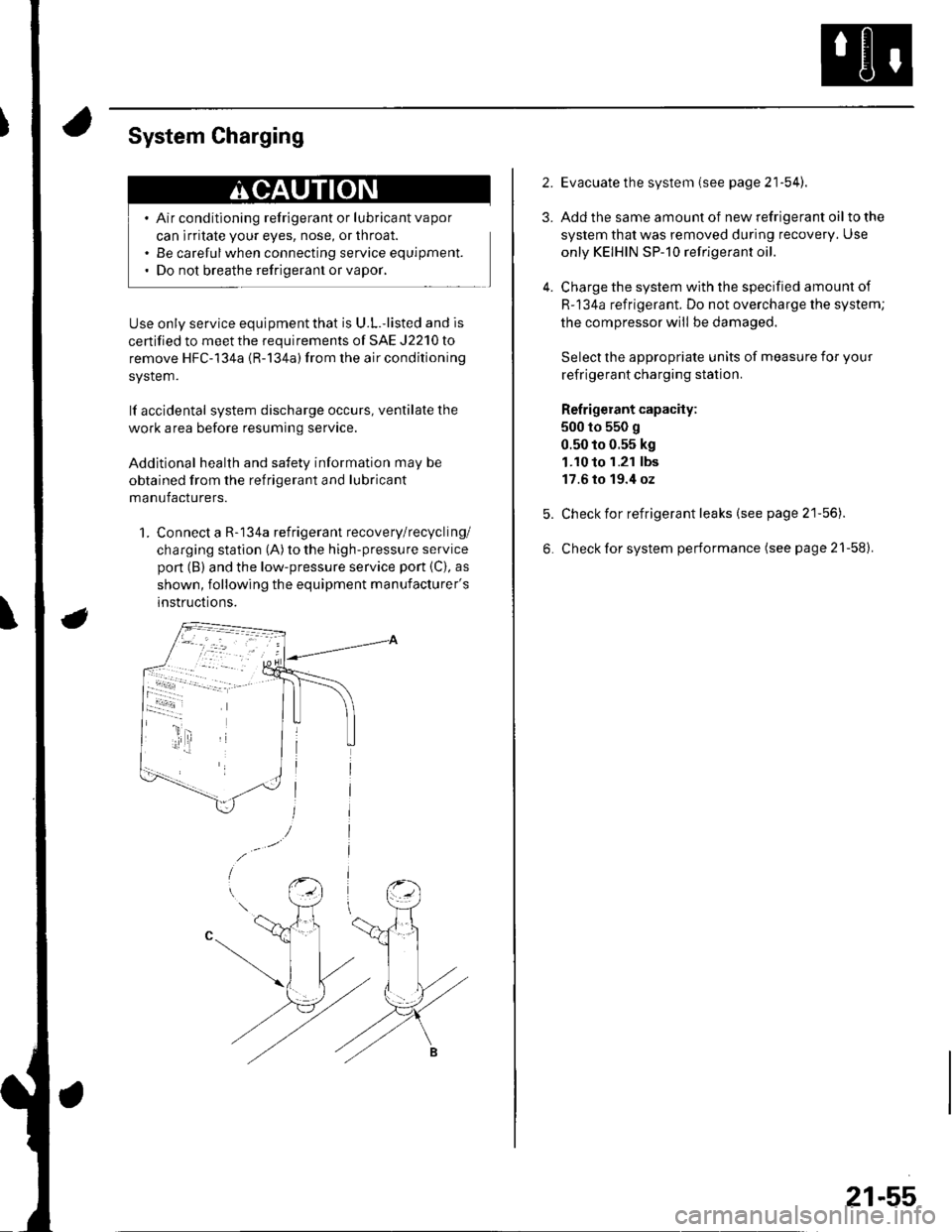
1. Connect a R-134a refrigerant recovery/recycling/
charging station (A) to the high-pressure service
pon (B) and the low-pressure service port {C), as
shown, following the equipment manufacturer's
instructions.
2.
3.
4.
Evacuate the system (see page 21'54).
Add the same amount of new refrigerant oil to the
system that was removed during recovery. Use
only KEIHIN SP-10 refrigerant oil.
Charge the system with the specified amount of
R-134a refrigerant. Do not overcharge the system;
the compressor will be damaged.
Select the appropriate units of measure for your
refrigerant charging station.
Refrigerant capacity:
500 to 550 g
0.50 to 0.55 kg
1.10 to 1.21 lbs
17.6 to 19.4 oz
Check for refrigerant leaks (see page 21'56).
Check for system performance (see page 21-58).
21-55
Page 827 of 1139
Heating and Air Conditioning
Refrigerant Leak Test
Special Tool Required
Leak detector, Honda Tool and Equipment YGK-H-10PM
commerciallv available
Compressed air mixed with R-134a forms a
combustible vapor.
The vapor can burn or explode causing serious
injury.
Never use compressed air to pressure test
R-134a service equipment or vehicle air
conditioning system.
Air conditioning refrigerant or lubricant vapor
can irritate your eyes, nose, or throat.
Be carefulwhen connecting service equipment.
Do not breathe refrigerant or vapor
Use only service equipment that is U.L.-listed and is
certiified to meet the requirements of SAE J2210 to
remove HFC-134a (R-134a) from the air conditioning
system.
lf accidental system discharge occurs, ventilate the
work area before resuming service.
R-134a service equipment or vehicle air conditioning
systems should not be pressure tested or leak tested
with compressed air.
Additional health and safety information may be
obtained from the refrigerant and lubricant
manufacturers.
21-56
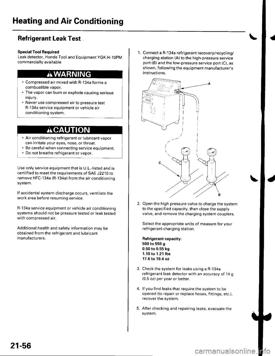
1. Connect a R-134a refrigerant recovery/recycling/
charging station (A) to the high-pressure serviceport (B) and the low-pressure service port (C), as
shown, following the equipment manufacturer's
anstructions.
Open the high pressure valve to charge the system
to the specified capacity, then close the supply
valve, and remove the charging system couplers.
Select the appropriate units of measure for your
refrigerant charging station.
Refrigerant capacity:
500 to 550 g
0.50 to 0.55 kg
1.10 to 1.21 lbs
17.6 to 19.4 oz
Check the system for leaks using a R-134a
refrigerant leak detector with an accuracy of 14 g(0.5 oz) per year or better.
lf you find leaks that require the system to be
opened (to repair or replace hoses, fittings, etc.),
recover the system.
After checking and repairing leaks, evacuate the
system.
3.