2002 HONDA CIVIC body electrical
[x] Cancel search: body electricalPage 40 of 1139
Starter Circuit Troubleshooting
NOTE:. Airtemperature must be between 59'and 100'F (15'
and 38'C) during this procedure.
. After this test, or any subsequent repair, reset the
engine controle module (ECM) to clear any diagnostlc
trouble codes (DTCS) {see page 11-4).. The battery must be in good condition and fully
charged.. lf you disconnect the baftery, do the ECM idle learn
procedure (see page 11-139).
Recommended Procedure:. Use a starter system tester.. Connect and operate the equipment in accordance
with the manuf acturer's instructions.
Alternate Procedure
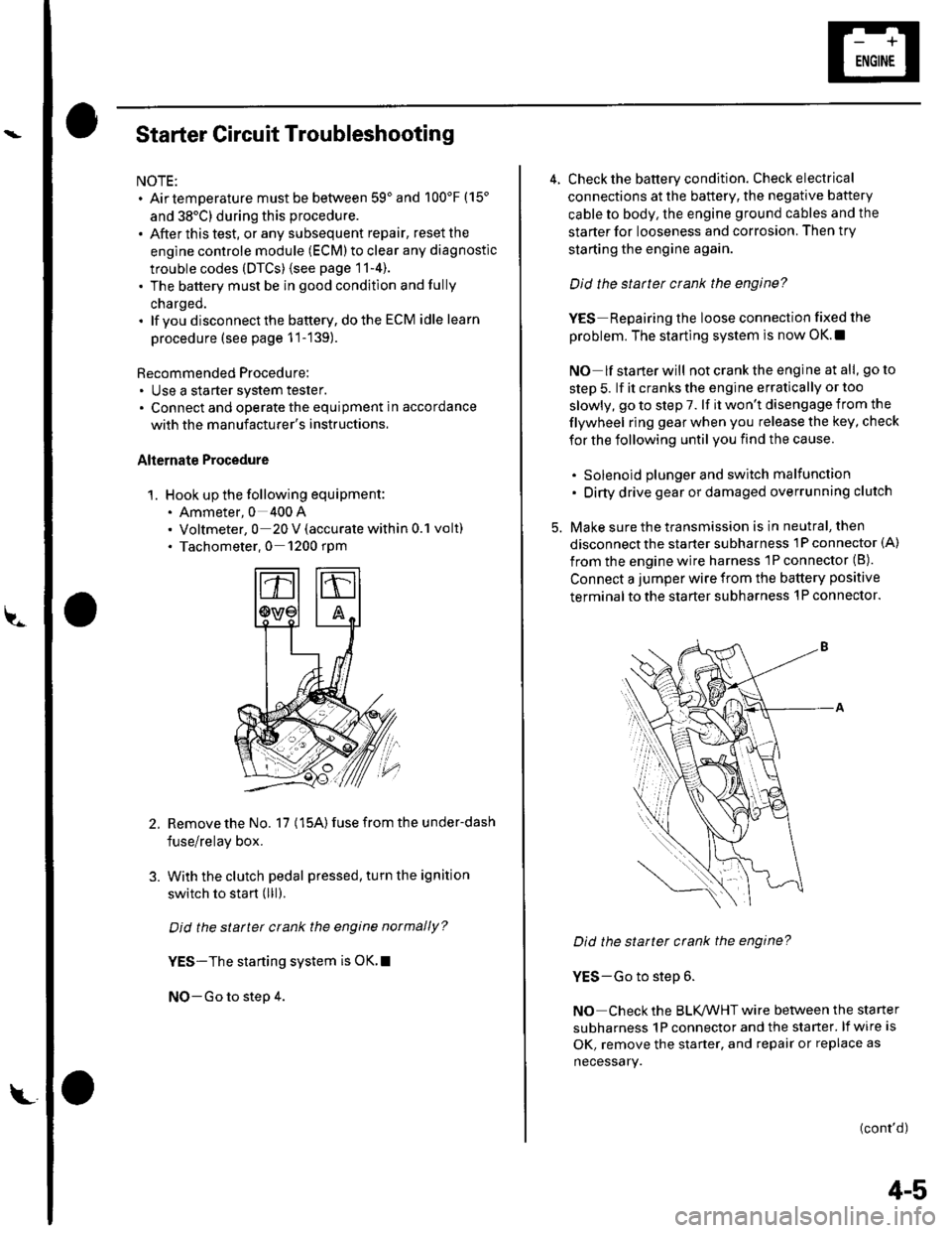
1. Hook up the following equipment:. Ammeter, 0 400 A. Voltmeter, 0 20 V (accurate within 0.1 volt). Tachometer,0 1200 rpm
2.Remove the No. 17 (15A) fuse from the under-dash
fuse/relay box.
With the clutch pedal pressed, turn the ignition
switch to start (lll).
Did the starter crank the engine normally?
YES-The starting system is OK.I
NO-Go to step 4.
3.
L
4-5
4. Check the battery condition. Check electrical
connections at the battery, the negative baftery
cable to body, the engine ground cables and the
starter for looseness and corrosion. Then try
starting the engine again.
Did the statter crank the engine?
YES Repairing the loose connection fixed the
problem. The starting system is now OK.!
NO lf starterwill notcranktheengine atall, goto
step 5. lf it cranks the engine erratically or too
slowly, go to step 7. lf it won't disengage from the
flywheel ring gear when you release the key, check
for the following until you find the cause.
. Solenoid plunger and switch malfunction. Dirty drive gear or damaged overrunning clutch
5. Make sure the transmission is in neutral, then
disconnect the starter subharness 1P connector (A)
from the engine wire harness 'lP connector (B).
Connect a jumper wire from the battery positive
terminal to the starter subharness 'l P connector.
Did the starter crank the engine?
YES-Go to step 6.
NO Check the BLK,ANHT wire between the starter
subharness 1P connector and the starter. lf wire is
OK, remove the starter, and repair or replace as
necessary.
(cont'd)
Page 239 of 1139
Fuel and Emissions Systems
(
{
System Descriptions (cont'd)
ldle Control System
When the engine is cold, the Ay'C compressor is on, the
transmission is in gear, the brake pedal is pressed. thepower steering load is high, or the alternator is
charging, the ECIM controls current to the ldle Air
Control (lAC) valve to maintain the correct idle speed.
Refer to the System Diagram to see the functional
layout of the system.
Brake Pedal Position Switch
The brake pedal position switch signals the ECM when
the brake pedal is oressed.
Electrical Power Steering (EPS) Senser
The EPS sensor signals the ECM when the power
steering load is high.
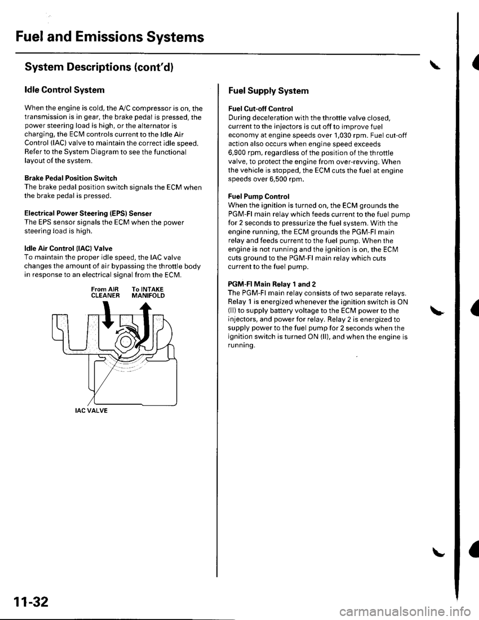
ldle Air Control llACl Valve
To maintain the proper idle speed, the IAC valve
changes the amount of air bypassing the throttle body
in response to an electrical signal from the ECM.
From AIR To INTAKECLEANER MANIFOLD
IAC VALVE
11-32
Fuel Supply System
Fuel Cut-off Control
During deceleration with the throttle valve closed,
current to the injectors is cut off to improve fuel
economy at engine speeds over 1,030 rpm. Fuel cut-off
action also occurs when engine speed exceeds
6,900 rpm, regardless of the position of the throttle
valve, to protect the engine from over-rewing. When
the vehicle is stopped. the ECM cuts the fuel at engine
speeds over 6,500 rpm.
Fuel Pump Control
When the ignition is turned on, the ECM grounds the
PGM-Fl main relay which feeds current to the fuel pump
for 2 seconds to pressurize the fuel system, With the
engine running. the ECM grounds the PGM-Fl main
relay and feeds current to the fuel pump. When the
engine is not running and the ignition is on, the ECI\4
cuts ground to the PGM-Fl main relay which cuts
current to the fuel pump.
PGM-FI Main Relay 1 and 2
The PGM-Fl main relay consists of two separate relays.
Relay 1 is energized whenever the ignition switch is ON(ll) to supply battery voltage to the ECM power to the
injectors, and power for relay, Relay 2 is energized to
supply power to the fuel pump for 2 seconds when the
ignition switch is turned ON (ll), and when the engine is
runnrng.
Page 342 of 1139

15. Check for continuity between body ground and
ECIM connector terminal 813.
ECM CONNECTOR B I24P}
Wire side of female terminals
ls there continuity?
YES Repair short in the wire between the ECM
(813) and the alternator.l
NO Update the ECM if it does not have the latest
software, or substitute a known-good ECM, then
recheck lsee page 1 1-6). lf the symptom/indication
goes away with a known-good ECM, replace the
original ECM.I
Electrical Power Steering (EPSI
Signal Circuit Troubleshooting
Turn the ignition switch ON (ll).
l\4easure voltage between ECM connector
terminals 424 and E16.
1.
2.
3.
4.
5.
Wire side of female terminals
ls there battery voltage?
YES Go to step 6.
NO Go to step 3.
Start the engine.
Turn the steering wheel lo the full lock position.
l\4easure voltage between ECM connector
terminals A24 and E16.
ls there momentaty battery voltage?
YES The EPS signal is OK.t
NO Go to step 10.
6. Turn the ignition switch OFF.
7. Disconnect the EPS control unit 20P connector.
8. Turn the ignition switch ON (ll).
(cont'd)
11-135
Page 343 of 1139
ldle Control System
Electrical Power Steering (EPSI Signal Circuit Troubleshooting (cont'd)
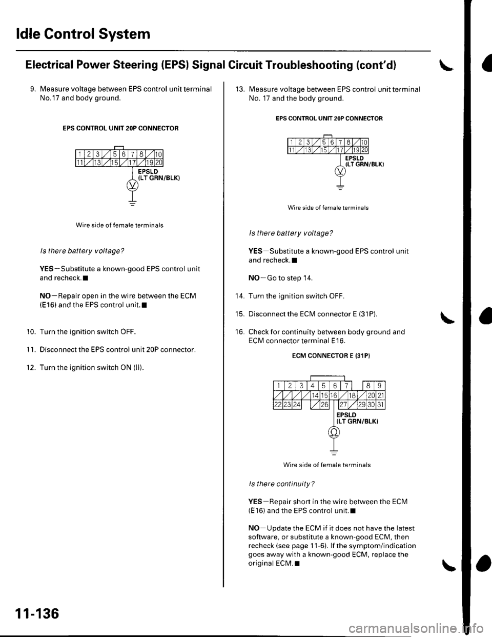
9. Measure voltage between EPS control unitterminal
No.l7 and body ground.
EPS CONTROL UNIT 2OP CONNECTOR
Wire side of female terminals
ls there battety voltage?
YES-Substitute a known-good EPS control unit
and recheck.I
NO- Repair open in the wire between the ECM(E 16) and the EPS control unit.l
Turn the ignition switch OFF.
Disconnect the EPS control unit 20P connector.
Turn the ignition switch ON (ll).
10.
I '�I.
12.
11-136
'13. l\4easure voltage between EPS control unitterminal
No. 17 and the body ground.
EPS CONTROL UNIT 2OP CONNECTOR
Wire side of female terminals
ls there battery voltage?
YES Substitute a known-good EPS control unit
and recheck.l
NO-Go to step 14,
Turn the ignition switch OFF.
Disconnectthe ECM connector E {31P).
Check for continuity between body ground and
ECI\4 connector terminal E16.
ECM CONNECTOR E {31PI
14.
t5_
16.
12345617l 189
56./182A21
2223zi ./29 30ol
EPSLD{LT GRN/BLK)
a,
Wire side ot Iemale terminals
lsthere continuity?
YES Repair short in the wire between the ECN4(E 16) and the EPS control unit.l
NO Update the ECM if it does not have the latest
software, or substitute a known-good ECM, then
recheck (see page 11-6). lf the symptom/indicationgoes away with a known-good ECM, replace the
original ECM.I
Page 346 of 1139
ECM ldle Learn Procedure
The idle learn procedure must be done so the ECM can
learn the engine idle characteristics.
Do the idle learn procedure whenever you do any of
these actions:. Disconnect the battery.
Replace the ECM or disconnect its connector.
Reset the ECM.
NOTE: Erasing DTCS with the Honda PGM Tester
does not require you to do the idle learn procedure.
Remove the No.6 ECU {ECM) ( 15A) fuse from the
under-hood fuse/relay box.
Remove the No.19 baftery (80A) fuse from the under-
hood fuse/relay box.
Remove PGM-FI main relay 1.
Remove any of the wires from the under-hood fuse/
retay Dox.
Disconnect any of the connectors from the under
hood fuse/relay box.
Disconnect the connector between the engine
compartment wire harness and ECM wire harness.
Disconnect the G2 terminal from the transmission
ho u srng.
Disconnectthe G'l terminal from the body.
Disconnectthe G101 terminal from the cylinder head
cover.
Procedure:
To complete the idle learn procedure, do this:
1. Make sure all electrical items (Ay'C, audio, rear
defogger, l:ghts, etc.,) are off.
2. Start the engine, and hold it at 3,000 rpm with no
load {in neutral) until the radiator fan comes on, or
until the engine coolanttemperature reaches 194"F(90'c).
3. Let the engine idle for about 5 minutes with the
throttle fully closed.
NOTE: lf the radiator fan comes on, do not include its
running time in the 5 minutes.
11-139
Page 831 of 1139
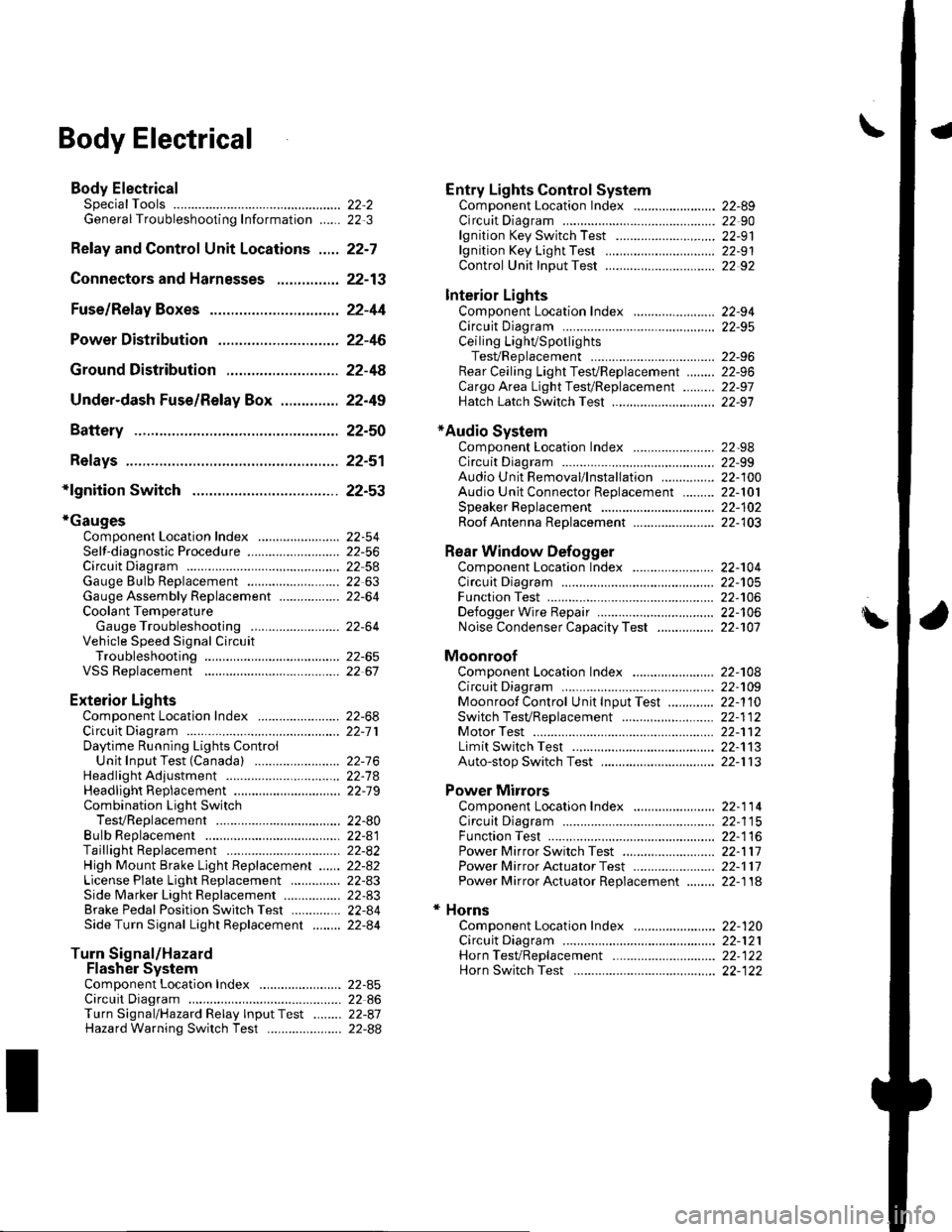
\Body Electrical
Body ElectricalSpecialToolsGeneral Troubleshooting tntorrnaiion.'......
Relay and Control Unit Locations .....
Connectors and Harnesses
Fuse/Relay Boxes ...............................
Power Distribution .............................
Ground Distribution ...........................
Under-dash Fuse/Relay Box ..............
Battery ..............
Relays ................
*lgnition Switch ..............
*Gauges
Component Location Index .......................Self-diagnostic Procedure ..........................Circuit DiagramGauge Bulb Replacement ..........................Gauge Assembly ReplacementCoolant Temperature
Gauge Troubleshooting .... ....................Vehicle Speed Signal CircuitTroubleshootingVSS Replacement
Exterior LightsComponent Location Index .......................Circuit DiagramDaytime Running Lights ControiUnit Input Test (Canada) ........................Headlight Ad,ustment .................. .. .....Headlighr Replacement ..............................Combination Light SwitchTest/ReplacementBulb ReplacementTaillight Replacement ..........................High Mount Brake Light Replacement ......License Plate Light Replacement ..............Side Marker Light Replacement ................Brake Pedal Position Switch Test ..............Side Turn Signal Light Replacement ........
Turn Signal/HazardFlasher SystemComponent Location Index .......................Circuit DiagramTurn Signal/Hazard Relay lnputTest ........Hazard Warning Switch Test
22,3
22-7
22-13
22-44
22-46
22-4A
22-49
22-50
22-51
22-53
22-5422-5622-5422 6322-64
22-64
22-6522 61
22-6822--71
22-7 622-7422-79
22-AO22-4122-8222-4222-4322-4322-4422-84
22-8�522 A622-8722-88
22-10422-105
22-10622-107
Entry Lights control systemComponent Location Index ....................... 22-89Circuit Diagram ......... 22 90lgnition Key Switch Test .....................,...... 22-9'llgnition Key Light Test ............................... 22-91Control Unit Input Test ..........,.................... 22 92
Interior LightsComponent Location Index ....................... 22-94Circuit Diagram ......... 22-95Ceiling LighVSpotlightsTesVReplacement ................................... 22-96Rear Ceiling Light TesVReplacem ent ........ 22-96Cargo Area Light Test/Replacem ent ......... 22-97Hatch Latch Switch Test ..,..,....................... 22-97
*Audio SystemComponent Location Index ....................... 22-98Circuit Diagram ......... 22,99Audio Unit Removal/lnstallation ............... 22-1OOAudio Unit Connector Replacement ......... 22-101Speaker Replacement ................................ 22-102Roof Antenna Rep1acement ....................-.. 22-103
Rear Window DefoggerComponent Location Index ...........Circuit Diasram .. ....... .. ..... ....... ...:::::.::.::.Function TestDefogger Wire Repair .................................Noise Condenser CapacityTest ................
MoonroofComponent Location Index ....................... 22-1OBCircuit Diagram ......... 22-109Moonroof Control Unit Input Test ............. 22-'l10Switch TesVReplacement ........,.....,........... 22-1 12Motor Test ................. 22-112Limit Swilch Test ...... 22-'l'13Auto-stop Switch Test ................................ 22-1 13
Power MirrorsComponent Location Index ....................... 22-114Circuit Diagram ......... 22-115Function Test ............. 22-116Power Mirror Switch Test .......................... 22-ll7Power Mirror Actuator Test ....................... 22-117Power Mirror Actuator Replacement ........ 22-11A
* HornsComponent Location Index ....................... 22-120Circuit Diagram ......... 22-121Horn TesVReplacement ...........................-. 22-122Horn Switch Test .,.... 22-122
\
Page 833 of 1139

Body Electrical
SpecialTools
@
Ref. No.Tool NumberDescription Otv
Q)
o)
o
07wAz-001010A
O7 LAJ - PT3 O 2OA
07TAz-001020A
MPCS Service Connector 1
Test Harness 1
Back Probe Adaotet 1
22-2
Page 835 of 1139

Body Electrical
General Troubleshooting Information (cont'd)
Check for loose retainer (A) and rubber seals (B).
The backs of some connectors are packed with
dielectric grease. Add grease if necessary. lf thegrease is contaminated, replace it.
lnsert the connector all the way and make sure it is
securelv locked.
Position wires so that the open end of the cover faces
oown.
22-4
Handling Wires and Harnesses. Secure wires and wire harnesses to lhe frame with
their respective wire ties at the designated locations.. Remove clips carefully; don't damage their locks (A).
Slip pliers (A) under the clip base and through the
hole at an angle, then squeeze the expansion tabs to
release the clip.
After installing harness clips, make sure the harness
doesn't interfere with any moving pans.
Keep wire harnesses away from exhaust pipes and
other hot parts, from sharp edges of brackets and
holes, and from exposed screws and bolts.
Seat grommets in their grooves properly {A). Do not
leave grommets distorted (B).
lt" /wl/
\--------\tfl r'---'..-
It
J
|,f . ./.ll t/
----E; F.�'l/
I