2002 HONDA CIVIC Pump
[x] Cancel search: PumpPage 17 of 1139

L
v
2-5
oi
Lubrication
a
a
nqlne
|temMeasurementOualificalionStanderd or New Service Limil
Engine oilCapacity5.3 0 (5.6 US qt)for engine overhaul
4.2 0 (4.4 US qt) for oil change, including filter
4.0 0 (4.2 US qt)for oil change, without filter
Oilpumplnner-to outer rotor clearance0.02 0.16 mm {0.001 0.006 in.)0.20 mm (0.008 in.)
Pump housing to outer rotor
clearance
0-15 0.21 mm {0.006-0.008 in.)0.23 mm (0.009 in.)
Pump housing-to-rotor axial
clearance
0.02 0.07 mm (0.001 0.003 in.)0.12 mm (0.005 in.)
Balancer shafts, journal diameterNo. 1 journal, front
shaft
19.938 19.950 mm 10.7850 0.7854 in.)19.92 mm (0.784 in.)
No 1 journal, rear shaft23.938 23.950 mm (0.9424 0.9429 in.)23.92 mm (0.942 in.)
No. 2 journal, front and
rear shaft
32.949 32.961 mm 11.2912 1.2911 in.l32.93 mm (1.296 in.)
Ealancer shafts, journal taper0.005 rnm (0.0002 in.) max.
Balancer shafts, end playFront0.070 0.135 mm (0.0028 0.0053 in.)0.15 mm (0.006 in.)
Rear0.070 0.135 mm (0.0028 0.0053 in.)0.15 mm (0.006 in.)
Balancer shatts, shaft-to'bear;ng
clearance
No. 1 iournal, front
shaft
0.050 0.082 mm (0.0020 0.0032 in.)0.10 mm (0.004 in.)
No. 1 Journal, rear shaft0.050 0.082 mm (0.0020 0.0032 in.) 0.10 mm (0.004 in.i
No. 2 journal, front and
rear shafl
0.060 -0.120 mm (0.0024 0.0047 in.) 0.15 mm (0.006 in.)
Balancer shaft bearings, LD.No. 1 journal, front
shaft
No. 1 iournal, rear shaft
20.000 20.020 mm (0.1814 0.7442 in.l
Z+.OOO ZI.OZO m- tOSa+e- OSa57 ir'.)
20.03 mm (0.789 in.)
24.03 mm (0.946 in.)
No. 2 journal, front and
rear shaft
33.021 33.069 mm (1.3000 1.3019 in.)33.09 mm {1.303 in.)
Reliefvalve, oil pressure with oil
temperature at 176'F (80"C)
At idle70 kPa (0.7 kq?cm , 10 psr) min.
At 3,000 rpm300 kPa {3.1 ksf/cm',44 psi)min.
Standard or New Service Limit
6.7 L (7.1 USCoolant capacity {includes engine,
heater, hoses, and reservoir)
0.53 L (0.56 US
93 123 kPa (0.95 1.25 kqtcm , 14 18 psi)'t69 176'F (76 80'C)Thermostat OPeningtemPerature
8.0 mm {0.31 in.) min.
Turns OFF Subtract 5 15'F (3 8"C)from actual ON
Page 23 of 1139

L
v
2-11
Design Specifications
O
o
o
|temMeasurementOualificationSpecilication
DIMENSIONSOveralllength4,210 mm {165.8 in.)
Overallwidth1,695 mm 166.7 in.)
Overallheight1,440 mm (56.7 in.)
2,570 mm (101.2 in.)
Trackrront1,470 mm (57.9 in.)
Rear'1,470 mm (57.9 in.i
Ground clearance152 mm (5.98 in.)
Seating capacityfour {4)
wEtGt-iT {u.s.A.)Gross Vehicle Weight Rating
(GVWR)
3,660 rbs
WEIGHT
(CANADA)
Gross Vehicle Weight Rating
{GVWR)
1,660 kg
ENGIN ETvpeWater cooled. 4 stroke DOHC V-EC engin(
Cylinder arrangementInline 4'cylinder, transverse
Bore and stroke86 x 86 mm (3.39 x 3.39 in.)
Displacement1,998 cm'(122 cu in.)
Compression ratio9.8
Valve trainChain drive. DOHC VTEC 4 valves per cylinder
Lubrication systemForced, wet sump, with trochoid pumP
Oil pump displacementAt 6,000 engine
rpm
54.3 0 (57.4 US qo/minute
Water pump displacementAt 3,400 engine82 0 (87 US qt)/minute
F!el requiredUNLEADED gasoline with 86 pump octane number or higher
STARTERTvpeGear reduction
Normaloutput
Nominalvoltage12V
Hour rating30 seconds
Direction of rotationClockwise as viewecl from gear end
CLUTCHClutch tvpeSinqle plate dry, diaphragm spring
Clutch friction material surface area174 cm'{26.97 sq in.)
I\,1AN UAL
TRANSMISSION
TvpeSvnchronized, s-speed forward, 1 reverse
Primarv reductionDirect 1:1
Gear ratiolst3.062
2nd1.769
3rd1.212
4th0.921
5th0.738
Reverse3.583
FinalreductionTypeSinole helicalgear
Gear ratio4.164
Page 95 of 1139

40. Install the air cleaner housinq.
6x1.0mm12 N m (1.2 kgf.m,8.7 lbt.ft)
Install the air cleaner housing cover (A) and
connect the intake air temperature (lAT) sensor
connector (B),
42. Installthe breather hose (C) and vacuum hose 1D).
41.
43. Installthe intake manifold cover.
6x1.0mm12Nm11.2kgf.m.8.7 tbf.ft)
Installthe battery. Clean the battery posts and
cable terminals with sandpaper, then assemble
them and apply grease to prevent corrosion.
Check that the transmission shifts into gear
smoothly.
Inspect for fuel leaks. Turn the ignition switch ON(ll) {do not operate the starter) so that the fuel pump
runs for about 2 seconds and pressurizes the fuel
line. Repeat this operation two or three times, then
check for fuel leakage at any point in the fuel line.
Refillthe engine with engine oil (see page 8-5).
Refill the transmission with fluid (see page 13-3).
Refill the radiator with engine coolant, and bleed
air from the cooling system with the heater valve
open (see page 10-6).
Perform the engine control module (ECM) idle learnprocedure (see page 11-139).
Inspect the idle speed (see page 1 1-138).
Inspect the ignition timing (see page 4-17).
Check the wheel alignment {see page 18-4).
Enter the anti-theft code for the radio, then enter
the customer's radio station presets.
Set the clock.
YE
44.
41.
]tE
46.
48.
49.
52.
53.
54.
50.
51.
55.
5-15
Page 136 of 1139

14. Installthe water bvpass hose.
15. Installthe air cleaner housing (see step 37 on page
5-15).
16. Installthe intake manifold (see page 9-5).
17. Installthe exhaust manifold (see page 9-7).
'18. Installthe cam chain (see page 6-15).
19. Adjust the valve clearance (seepage6-9).
20. Installthe drive belt (see page 4-26).
21. Clean the battery posts and cable terminals with
sandpaper, then assemble them and apply grease
to prevent corrosion.
22. After installation, checkthatall tubes, hosesand
connectors are installed correctly.
23. Inspectforfuel leaks. Turn the ignition switch ON
{ll) {do not operate the starter) so that the fuel pump
runs for about 2 seconds and pressurizes the fuel
line. Repeat thls operation two or three times, then
check for fuel leakage at any point in the fuel line.
24. Refillthe radiator with engine coolant, and bleed
air from the cooling system with the heater valve
open (see page 10-6).
25. Inspect the idle speed (see page 11-'138).
26. Inspect the ignition timing (see page 4-17).
Gylinder Head Cover lnstallation
1. Thoroughly clean the head cover gasket and the
groove.
2. Installthe head cover gasket (A) in the groove of
the cylinder head cover (B).
Check that the mating surfaces are clean and dry.
Apply liquid gasket. P/N 08718-0009, on the chain
case and the No.5 rocker shaft holder mating areas.
NOTE: Do not install the parts if 5 minutes or more
have elapsed since applying liquid gasket. Instead,
reapply liquid gasket after removing old residue.
(cont'd)
6-41
Page 143 of 1139

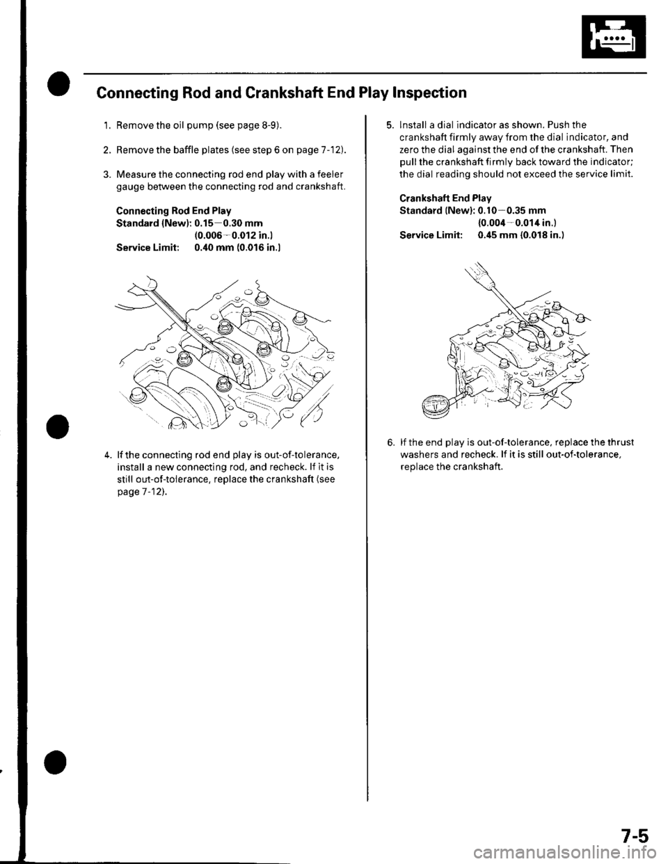
Connecting Rod and Crankshaft End Play Inspection
1.Remove the oil pump (see page 8-9).
Remove the baffle plates (see step 6 on page 1 -12).
3. Measure the connecting rod end play with a feeler
gauge between the connecting rod and crankshaft.
Connecting Rod End Play
Standard {New): 0.15 0.30 mm(0.006-0.012 in.l
Service Limit 0.40 mm (0.016 in.l
4.lf the connecting rod end play is out-of-tolerance,
install a new connecting rod, and recheck. lf it is
still out-of-tolerance, replace the crankshaft (see
page 7 -12],.
5. lnstall a dial indicator as shown. Push the
crankshaft firmly away from the dial indicator, and
zero the dial against the end of the crankshaft. Then
pull the crankshaft firmly back toward the indicator;
the dial reading should not exceed the service limit.
Crankshaft End Plav
Standard lNew): 0.10-0.35 mm
{0.004-0.014 in.l
Service Limit: 0.45 mm {0.018 in.)
lf the end play is out-of-tolerance, replace the thrust
washers and recheck. lf it is still out-of-tolerance,
replace the crankshaft.
7-5
Page 146 of 1139

Engine Block
Crankshaft Main Bearing
Replacement (cont'd)
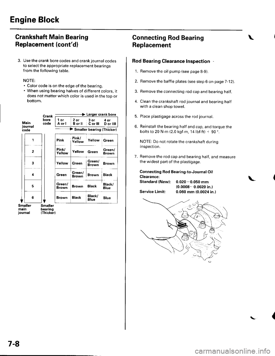
3. Use the crank bore codes and crank journal codes
to select the appropriate replacement bearings
from the following table.
NOTE:. Color code is on the edge of the bearing.. When using bearing halves of different colors. it
does not matter which color is used in the top or
bottom.
Mainiournslcooe
Crank ---=-> Lalger crank bore
bore | 1or 2ot 3or c oi__-lcode IAorl Borll Corlll Dortttt I-- --> Smaller bearing {Thickerl
(Thicker)
1
2
4
5
Pink f!1f;* v"rro* c,""n
ll
f111f;,," v"no* c,""" $;;fl
cr""n $ffi ero-n
ffi#Tr,.*" i.,""*Creen ; g=jiff;i Brown Black
;;lT]*
'---l-'o"*,
Brown Black 6il;
Brack !l;kr ar*
7-8
Connecting Rod Bearing
Replacement
Rod Bearing Clearance lnspection
1. Remove the oil pump (see page 8-9).
2. Bemove the baffle plates (see step 6 on page 7-12).
3. Remove the connecting rod cap and bearing half.
4. Clean the crankshaft rod journal andbearinghalf
with a clean shop towel.
5. Place plastigage across the rod journal.
6. Reinstallthe bearing half and cap, and torque the
bolts to 20 N.m (2.0 kgf.m, 14lbf.ft) -l 90 ".
NOTE: Do not rotate the crankshaft during
inspection.
7. Remove the rod cap and bearing half, and measure
the widest part of the plastigage.
Connecting Rod Bearing-to-Journal Oil
Clearance:
Standard {Newl: 0.020 0.050 mm(0.0008 --0.0020 in.l
Service Limit: 0.060 mm (0.0024 in.)
\
\-
{
Page 150 of 1139

Engine Block
Crankshaft and Piston Removal
1. Remove the engine assembly (see page 5-2).
2. Remove the transmission (see page 13-4).
3. Remove the oil pan (see page 7-1 1).
4. Remove the oil pump {see page 8-9).
5. Remove the cylinder head (see page 6-23).
6. Remove the baffle plates.
7. Remove the 8 mm bolts.
E
7-12
8. Remove the bearing cap bolts. To prevent warpage,
unscrew the bolts in sequence 1/3 turn at a time:
repeat the sequence until all bolts are loosened.
Remove the lower block and bearings, Keep all
bearings in order.
\L
(
Page 165 of 1139

23. Install the baffle plates.
6x1.0mm12 N.m(1.2 ksf m, 8.7 lbf ft)
24. Installthe oil pump (see page 8-14).
25. Installthe oil pan (see page 7-27).
26. Installthe cylinder head (see page 6-39).
27. Installthe transmission (see page 13-8).
28. Installthe engine assembly (see page 5-9).
1.
OilPan lnstallation
Remove old liquid gasket from the oil pan mating
surfaces, bolts, and bolt holes.
Clean and dry the oil pan mating surfaces.
Apply liquid gasket, P/N 08718-0009, evenly to the
cylinder block mating surface of the oil pan and to
the inner threads of the bolt holes.
NOTE: Do not install the parts if 5 minutes or more
have elapsed since applying liquid gasket. Instead,
reapply liquid gasket after removing old residue.
Installthe oil pan.
Tighten the bolts in two or three steps. In the final
step, tighten all bolts, in sequence, to 12 N.m (1.2
kgf m, 8.7 lbf.ft).
(cont'd)
2.
3.
4.
5.
Apply liquid gasketalong the broken line.
(}@
7-27