Page 169 of 1139
Component Location Index
OIL PUMPCHAIN TENSIONER
DRAIN BOLT
OIL PANRemoval, page 7 11Installataon, page 7-27
OIL PUMPOverhaLrl, page 8-8
HL]
BAFFLE PLATE
OIL FILTER FEED PIPEReplacement, page 8-7
OIL FILTERReplacement, page 8-6
OIL CONTROLORIFICE
WASHER
OIL PRESSURE SWITCHSwitch Test, page 8 4Oil Pressure test, page 8'4Replacement, page 8 16
-&\JrI
--t N\ksrarr lN-?cKEr dczt$)
#1
\OIL PUMPCHAIN GUIDE
8-3
Page 170 of 1139

Engine Lubrication
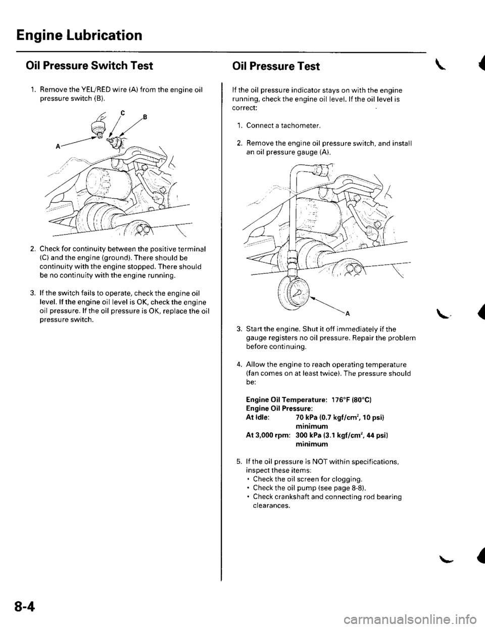
Oil Pressure Switch Test
1. Remove the YEURED wire (A)from the engine oilpressure switch (B).
Check for continuity between the positive terminal(C) and the engine (ground). There should be
continuity with the engine stopped. There should
be no continuity with the engine running.
lf the switch fails to operate, check the engine oil
level. lf the engine oil level is OK. check the engine
oil pressure. lf the oil pressure is OK, replace lhe oil
Dressure switch.
2.
8-4
Oil Pressure Test
lf the oil pressure indicator stays on with the engine
running. check the engine oil level. lf the oil level is
correct:
Connect a tachometer.
Remove the engine oil pressure switch, and install
an oil pressure gauge {A).
{
'1.
\.(
4.
Sta rt the engine. Shut it off immediately if thegauge registers no oil pressure. Repair lhe problem
before continuing.
Allow the engine to reach operating temperature(fan comes on at least twice), The pressure should
be:
Engine Oil Temperature: 176'F (80'Cl
Engine Oil Pressure:
At ldle:70 kPa (0.7 kgf/cm', 10 psi)
mtntmum
At 3,000 rpm: 300 kPa (3.1 kgf/cm',44 psi)
minimum
lf the oil pressure is NOT within specifications,
inspect these items:. Check the oil screenforclogging.. Check the oil pump (see page 8-8).. Check crankshaft and connecting rod bearing
clearances.
I
Page 174 of 1139
Engine Lubrication
OilPump Overhaul
Exploded View
BAFFLE PLATE6x1.0mm12 N.m{1.2 kgf m,8.7 lbf.ft)
x 1.25 mm27 N.m6x1.0mm12 N.m11.2 kgf.m, 8.7 lbt ft)
(2.8 kst m, 20 lbt ft)Apply engine oiltothe bolt threads.
UPPER BALANCERSHAFT HOLDER
BALANCER SHAFTBEARINGS
Ptr
PU II
EU "
DOWEL PIN
REARBALANCERSHAFT
\
- /=.---'n
fs/
tw
FRONTBALANCERSHAFT
LOWERSHAFTBALANCERHOLDERSEALING BOLT39 N.m{4.0 kgf.m,29lbf.ftl
$--."Dowetem
8-8
\-
Page 175 of 1139
Oil Pump Removal
1. Setthe No. 1 piston attop dead center {TDC) {see
step 1 on page 6-12).
2. Remove the oil pan(seepageT-11).
3. Remove and discard the oil pumpchaintensioner.
4. To hold the rear balancer shaft, insert a 6 mm pin
driver (A) into the maintenance hole in the lower
balancer shaft holder and through the rear balancer
shaft.
5. Loosen the oil pump sprocket mounting bolt.
6. Remove the oil pump sprocket (A), then remove the
oil pump (B).
(cont'd)
8-9
Page 176 of 1139

Engine Lubrication
Oil Pump Overhaul {cont'dl
Oil Pump Inspection
1. Remove the pump housing.
Check the inner-to-outer rotor radial clearance
between the inner rotor (A) and outer rotor {B). lf
the inner-to-outer rotor radial clearance exceeds
the service limit, replace the oil pump.
Inner Rotor-to-Outer Botor Radial Clearance
Standard {New): 0.02 0.16 mm (0.001 -0.006 in.)
Service Limit: 0.20 mm (0.008 in.,
1'[1e-\1.-,-2
1 'a - :.: ,-'r'
8-10
\-
{
4.
3. Check th e h ousing-to-roto r axia I clearance between
the rotor (A) and pump housing (B). lf the housing-
to-rotor axial clearance exceeds the service limit.
replace the oil pump.
Housing"to-Rotor Axial Clearance
Standard (New): 0.02 0.07 mm (0.001 -0.003 in.l
Service Limit: 0.12 mm (0.005 in.l
Check the housing-to-outer rotor radial clearance
between the outer rotor (A) and pump housing (B).
lf the housing-to-outer rotor radial clearance
exceeds the service limit, replace the oil pump.
Housing-to-Outer Rotor Radial Clearance
Standard lNewl: 0.15 0.21 mm (0.006-0.008 in.l
Service Limit; 0.23 mm (0.009 in.)
Inspect both rotors and the pump housing for
scoring or other damage. Replace parts if
necessary.
\,
Page 177 of 1139
1.
Balancer Shaft Inspection
Seat the balancer shaft by pushing it away from the
oil pump sprocket end ofthe oil pump.
Zero the dial indicator against the end of the
balancer shaft, then push the balancer shaft back
and forth and read the end olav.
Balancer Shaft End Play:
Fronl Balancer Shaft:
Standard {Newl: 0.070 0.135 mm
{0.0028 0.0053 in.}
Service Limit: 0.15 mm (0.006 in.)
Rear Balancer Shaft:
Standard {New): 0.070-0.135 mm(0.0028 0.0053 in.l
Service Limit: 0.15 mm (0.006 in.)
2.
3. Remove the baffle plate (A) and upper balancer
shaft holder {with bearings) (B), then remove the
front balancer shaft (C) and rear balancer shaft (D).
9H.A''/.r L=] j/
R
Rfl|]
3I] UUr Be
+-
(cont'd)
8-11
Page 178 of 1139
Engine Lubrication
Oil Pump Overhaul (cont'dl
4. Measure the inner diameter of the No. 1 bearing for
the front balancer shaft hole and the rear balancer
shaft hole.
Bearing Inner Diameier:
Front:
Standard (New): 20.000-20.020 mm(0.7874 0.7882 in.)
Service Limit; 20.03 mm (0.789 in.)
Rear:
Standard (New): 24.000-24.020 mm
10.9/t49-0.9457 in.)
Service Limit: 24.03 mm (0.946 in.)
Front:
Rear:
8-12
\
(
5.Measure the diameters of the No. 1 journals on the
front balancer shaft and rear balancer shaft.
NO.1 Journal Diameter:
Front:
Standard lNew): 19.938 19.950 mm(0.7850 0.7854 in.)
Service Limit: 19.92 mm {0.784 in.)
Rear:
Standard lNewl: 23.938 23.950 mm
{0.9424-0.9/129 in.)
Service Limit: 23.92 mm (0.942 in.)
Front:
a
Page 180 of 1139
Engine Lubrication
Oil Pump Overhaul (cont'd)
13. lnstallthe pump housing.
6x1,0mm12 N.m(1.2 kgt.m,8.7 lbf.ft)
8-14
!
Oil Pump Installation
1. Make sure the No. 1 piston is at TDC (see step 1 on
page 6-12).
2. Align the dowel pin{A} on the rear balancer shaft
with the mark (B) on the oil pump.
To hold the rear balancer shaft, insert a 6 mm pin
driver {A) into the maintenance hole in the lower
balancer shaft holder and through the rear balancer
shaft.\,-
9%ttrc
+:.:4.4 / t \
o/.-lY\
:aa:'
-rr
dv
f,o-;