2002 HONDA CIVIC reset
[x] Cancel search: resetPage 888 of 1139

\
The LCD Segment Check:
When entering the self-diagnosis mode, the odo/trip segment blinks five times.
The Gauge Drive Circuit Check:
When entering the self-diagnosis mode, the speedometer, the tachometer, the fuel gauge, and the coolant
temperature gauge needles sweep from the minimum position to maximum position, then return to the minimum
posrtron.
NOTE: After the beeper stops sounding and the needles return to the minimum position, pushing the trip/reset button
starts the beeper drive circuit check (one beep) and the gauge drive circuit check again.
The check cannot be started untilthe needles return to the minimum position.
Self-diagnosismode
Trip/Resetswitch
ON
OFF
ON r-r r-r r-r .-1 r-r r-r
;; lll u u l_l L__l I l-l
5 sec
Faulty:
The needles sweep from theminimum position to themaximum position, then returnto the minimum position-
Normal:
iD
tli-
flOi-
Ending the self-diagnosis function:
Turn the ignition switch OFF.
NOTEr lf the vehicle speed exceeds 1.2 mph {2 km/h), the self diagnosis fu nction ends.
:-l!:!!JlJ!J
,-
t,-- - ,- r- i-
| | | ttfi- r-
9l- r n =--llJL--oFF _---
cause needles Xl" f---U---------l [-----l
Beeper
The Communication Line Check:
In the self-diagnosis mode, after the odo/trip LCD segments check, the self-diagnosis starts the communication line
cnecK.
lf all segments comes on, the communication line is OK.
lf the word "Error" is indicated, there is a malfunction in the communication line between the gauge assembly. the
multiDlex control unit. and the ECM.
@,
22-57
Page 931 of 1139

Audio System
Audio Unit Removal/lnstallation
NOTE:. Put on gloves to protect your hands.. Take care not to scratch the dashboard and relatedpa rts.
1. Make sure you have the anti-theft code for the radio,
then write down the frequencies for the radio's
preset buttons.
2. Remove the driver's dashboard lower cover (see
page 20-59).
3. Remove the two mounting bolts, then pull out the
center panel (A).
4.Disconnect the audio connector (B) and antenna
lead (C), heater control panel connectors (D) and
HAVC push switch assembly (E), then remove the
center panel.
22-100
!\,
7.
Remove the heater control panel (see page 21 38).
Remove the four mounting bolts and the audio unit
from the radio brackets.
Installthe audio unit in the reverse order of
removal, and note these items:
. Make sure the audio unit and A/C connectors areplugged in properly, and the antenna lead is
connected properly.. Enter the anti-theft code for the radio, then enter
the customer's radio station presets.
\v
I
Page 992 of 1139

Transmitter Test
NOTE:. lf the doors unlockorlockwiththetransmitter, but
the LED on the transmitter does not come on, the LED
is faulty. Replace the transmitter,. lf anydoor isopen, you cannotlockthedoorwiththe
transmrtter.. lf you unlocked the doors with the transmitter, but do
not open any of the doors within 30 seconds, the
doors relock automatically.. The doors do not lock or unlock with the transmitter if
the ignition key is inserted in the ignition switch.
1. Press the lock or unlock button five or six times to
reset the transmitter.
. lf the locks work, the transmitter is OK.. lf the locks don't work, go to step 2.
2. Open the transmitter and check for water damage.
. lf you find any water damage, replace the
transmrtter.. lf there is no waterdamage, go to step 3.
3. Replace the transmitter battery (A) with a new one,
and try to lock and unlock the doors with the
transmitter by pressing the lock or unlock button
five or six times.
. lf the doors lock and unlock, the transmifter is OK.. lf the doors don't lock and unlock, go to step 4.
Reprogram the transmitter, then try to lock and
unlock the doors.
. lf thedoors lockand unlock.thetransmitter is OK.. lf the doors don'tlockand unlock, replacethe
transmitter.
4.
Transmitter Programming
Storing transmitter codes:
The codes of up to three transmitters can be stored in
the keyless receiver unit memory. (lf a fourth code is
stored. the code which was input first will be erased.)
NOTE: lt is important to maintain the time limits
between the steps. Make sure the doors and the hatch
are closed.
1. Turn the ignition switch ON (lli.
2. Within 1 to 4 sec., push the transmitter lock or
unlock button with the transmitter aimed at the
receiver in the multiplex control unit behind the
driver's side of the dash.
3. Within 1 to 4 sec., turn the ignition switch OFF.
4. Within 1 to 4 sec., turn the ignition switch ON (ll).
5. Within 'l to 4 sec., push the transmitter lock or
unlock button with the transmitter aimed at the
receiver in the multiplex control unit behind the
driver's side of the dash.
6. Within 1 to 4 sec., turn the ignition switch OFF.
7. Within 4 sec., turn the ignition switch ON (ll).
8. Within 1 to 4 sec., push the transmitter lock or
unlock button with the transmifter aimed at the
receiver in the mupltiplex control unit behind the
driver's side of the dash.
9. Within 1 to 4 sec., turn the ignition switch OFF,
'10. Within 4 sec., turn the ignition switch ON (ll).
11. Within 1 to 4 sec., push the transmitter lock or
unlock button with the transmitter aimed at the
receiver in the multiplex control unit behind the
driver's side of the dash.
12. Confirm you can hearthe sound ofthe door lock
actuators. Within 1 to 4 sec., push the transmitter
lock or unlock button again,
13, Within 10 sec., aim the transmitters (up to two
additional ones) whose codes you want to store at
the receiver, and press the transmitter lock or
unlock buttons.
Confirm that you can hear the sound of the door
lock actuators after each transmitter code is stored.
14. Turn the ignition switch OFF, and pull out the key.
'15. Confirm proper operation ofthe transmitter.
22-161
Page 994 of 1139

System Description
The vehicle is equipped with an immobilizer system that will disable the vehicle unless the proper ignition key is used.This system consists of a transponder located in the ignition key, an immobilizer control unit-receiver, an indicatorlight, and the ECM.
When the key is inserted in the ignition switch and turned to the ON {ll) position, the immobilizer control unit-receiversends power to the transponder in the ignition key. The transponder then sends a coded signal back to the immobilizer
control unit-receiver which then sends a coded signal to the ECI\4.
iEl'JUiliii'tlun"oona"|.r KEYCYLTNDER
lf the proper key has been used, the immobilizer indicator light will come on for about 2 seconds, then go off.lf the wrong key has been used or the code was not received or recognized by the unit, the indicator light will comeon for about 2 seconds, then it will blink until the ignition switch is turned OFF.lf the ignition switch is turned OFF, the indicator will blink for about 5 seconds to signal that the unit has reset
correctly, then the indicator will go off.
lf the customer has lost his key, and cannot start the engine, contact Honda Customer Relations.
IMMOBILIZER INDICATOR LIGHT BLINKING PATTERN:
IGNITION SWITCHON
OFF
PROPER KEYINSERTEDINDICATORLIGHTON
WRONG KEYINSERTEDINDICATORLIGHTON
OFF
(| i.,
IMMOBILIZER CONTROL UNIT.RECEIVER
)
22-163
Page 1012 of 1139

Seat Belts
Front Seat Belt Replacement
SRS comDonents are located in this area. Review the
SRS component locations (see page 23-13) and the
precautions and procedures (see page 23-14) in the SRS
section before performing repairs or service,
NOTE: Check the front seat belts for damage, and
replace them if necessary. Be careful not to damage
them during removal and installation.
Front Seat Belt
Make sure you have the anti-theft code for the radio,
then write down the frequencies for the preset
buttons.
Disconnect the negative cable from the battery, and
wait at least 3 minutes before beginning work.
Slide the front seat forward fully.
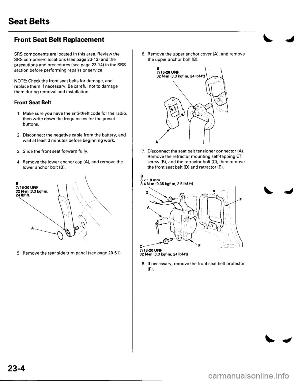
Remove the lower anchor cap (A), and remove the
lower anchor bolt (B).
3.
1.
5. Remove the rear side trim panel (seepage20-51).
23-4
qt
B7/16-20 UNF32 N m (3.3 kgf.m,24lbt.ft)
7. Disconnect the seat belt tensioner connector (A).
Remove the retractor mounting self-tapping ET
screw {B), and the retractor bolt (C), then remove
the front seat belt (D) and retractor (E).
6x1.0mm3.4 N m {0.35 kgf.m,2.5 lbf.ft)
6. Remove the upper anchor cover {A), and remove
the upper anchor bolt (B).
7/16-20 UNF32 N.m (3.3 kgf m,2ir lbf.ft)
8. lf necessary, remove the
(F).
front seat belt protecto
Page 1013 of 1139

9.
10.
Remove the B-pillar upper trim {see page 20-50)
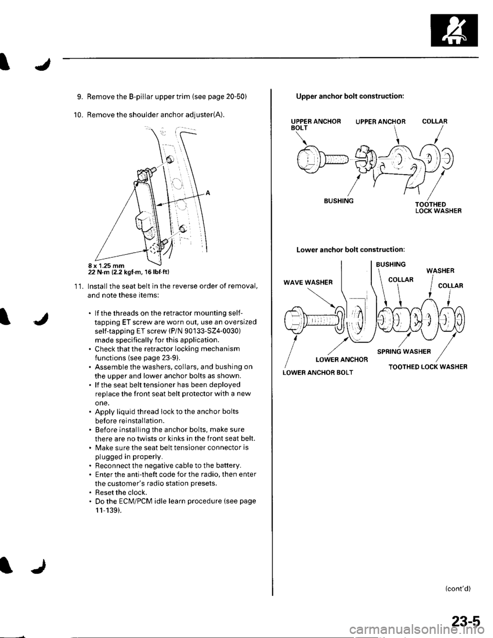
Remove the shoulder anchor adjuster{A).
22 N.m (2.2 kgf.m, 16lbf.ftl
Installthe seat belt in the reverse order of removal,
and note these items:
. lf thethreads on the retractor mounting self-
tapping ET screw are worn out, use an oversized
self-tapping ET screw (P/N 90133-SZ4-0030)
made specifically for this application.. Check that the retractor locking mechanism
functions (see page 23-9).. Assemble the washers, collars, and bushing on
the upper and lower anchor bolts as shown.. lf the seat belt tensioner has been deployed
replace the front seat belt protector with a new
one.. Apply liquid thread lock to the anchor bolts
before reinstallation.. Before installing the anchor bolts, make sure
there are no twists or kinks in the front seat belt.. Make sure the seat belt tensioner connector is
plugged in properly.
. Reconnect the negative cable to the battery.. Enter the anti-theft code for the radio, then enter
the customer's radio station presets.
. Reset the clock.. Do the ECM/PCM idle learn procedure {see page
11,139).
11.
8 x 1.25 mm
UPPER ANCHORBOLT
BUSHING
Upper anchor bolt construction:
UPPER ANCHOR
Lower anchor bolt construction:
COLLAR
TOOTHEDLOCK WASHER
LOWER ANCHOR BOLTTOOTHED LOCK WASHER
{cont'd)
WASHER
23-5
Page 1014 of 1139

Seat Belts
Front Seat Belt Replacement (cont'd)
Seat Belt Buckle
1. Make sure you have the anti-theft code for the radio,
then write down the frequencies for the preset
buttons.
2. Disconnect the negative cable from the battery ,and wait at least 3 minutes before beginning work.
3. Remove the front seat (see page 20-7'1).
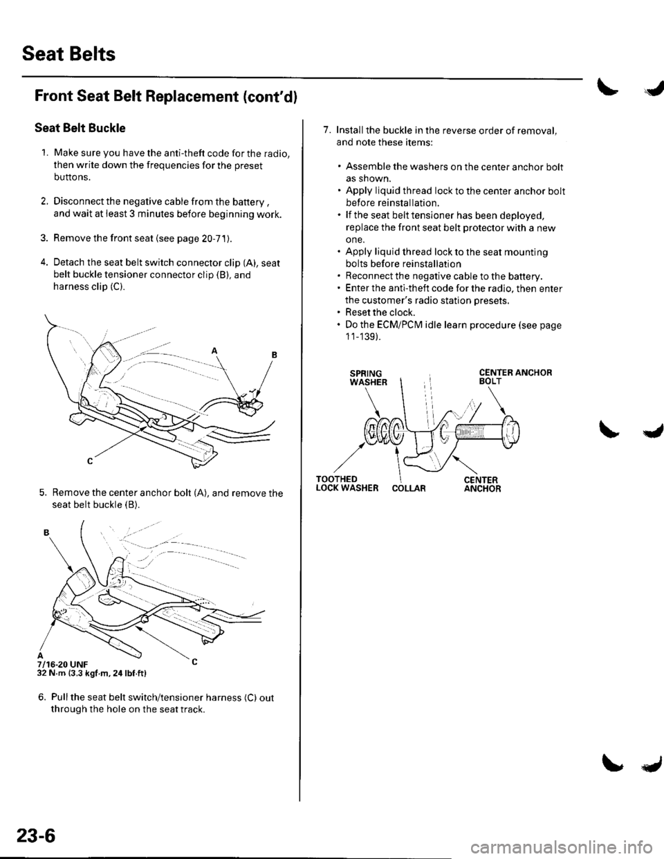
4. Detach the seat belt switch connector clip (A), seat
belt buckle tensioner connector clip (B), and
harness clip (C).
5. Remove the center anchor bolt (A), and remove the
seat belt buckle {B).
7/16-20 UNF32 N m {3.3 kgf m,24lbf.ft)
6. Pullthe seat belt switch/tensioner harness (C) out
through the hole on the seat track.
. -.. :.a--
23-6
7. Installthe buckle in the reverse order of removal,
and note these items:
. Assemble the washers on the center anchor bolt
as shown.. Apply liquid thread lock to the center anchor bolt
before reinstallation.. lf the seat belt tensioner has been deployed,
replace the front seat belt protector with a new
one.. Apply liquid thread lock to the seat mounting
bolts before reinstallation. Reconnect the negative cable to the battery.. Enter the anti-theft code for the radio, then enter
the customer's radio station presets.. Reset the clock.. Do the ECMiPCM idle learn procedure (see page
1 1_139).
COLLAR
Page 1021 of 1139

sRs
Precautions and Procedures
General Precautions
Please read the following precautions carefully beforeperforming airbag system service. Observe theinstructions described in this manual. or the airbags
could accidentally deploy and cause damage or injuries.
. Except when performing electrical inspections.
always turn the ignition switch OFF, disconnect the
negative cable from the battery, and wait at least 3minutes before beginning work.
NOTE: The memory is not erased even if the ignition
switch is turned OFF or the battery cables are
disconnected from the battery.. Use replacement pans which are manufactured to the
same standards and quality as the original parts. Do
not install used SRS parts from another vehicle. Useonly new pans when making SRS repairs.. Carefully inspect any SRS part before you install it.
Do not install any part that shows signs of being
dropped or improperly handled, such as dents, cracks,
or deformation.
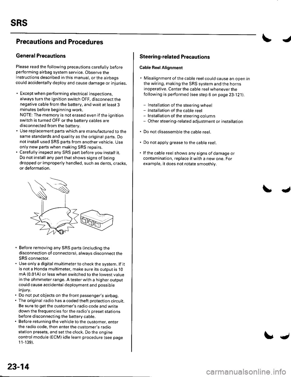
. Before removing any SRS parts (including the
disconnection of connectors), always disconnect the
SRS connector.. Use only a digital multimeter to check the system. lf itis not a Honda multimeter, make sure its outout is 10mA (0.01A) or less when switched to the lowest value
in the ohmmeter range. A tester with a higher output
could cause accidental deployment and possible
injury.. Do not put objects on the front passenger's airbag.. The original radio has a coded theft protection circuit.
Be sure to get the customer's radio code and write
down the frequencies for the radio's preset stations
before disconnecting the battery cable.. Before returning the vehicle to the customer, enter
the radio code. then enter the customer's radio
station presets, and set the clock. Do the engine
control module (ECM) idle learn procedure (see page
11-139).
23-14
c
Steering-related Plecautions
Cable Reel Alignment
. Misalignment of the cable reel could cause an open in
the wiring, making the SRS system and the horns
inoperative. Center the cable reel whenever the
following is performed (see step 6 on page 23-121).
- Installation of the steering wheel- Installation of the cable reel- Installation ofthe steering column- Other steering-related adjustment or installation
. Do not disassemble the cable reel.
. Do not apply grease to the cable reel.
. lf the cable reel shows any signs of damage or
contamination. replace it with a new one. For
example, it does not rotate smoothly.