Page 155 of 1139
Cylinder Honing
Only a scored or scratched cylinder bore should be
noneo.
Measure the cylinder bores {see page 7-15).
lf the block is to be reused, hone the cylinders and
remeasure the bores.
Hone the cylinder bores with honing oil and a fine(400 grit) stone in a 60 degree cross-hatch pattern
(A). Use only a rigid hone with 400 grit or finer
stone such as Sunnen, Ammco, or equivalent. Do
not use stones that are worn or broken.
When honing is complete, thoroughly clean the
engine block of all metal particles. Wash the
cylinder bores with hot soapy water, then dry and
oil them immediately to prevent rusting. Never use
solvent, it will only redistribute the grit on the
cylinder walls.
lf scoring or scratches are still present in the
cylinder bores after honing to the service limit,
rebore the cylinder block. Some light vertical
scoring and scratching is acceptable if it is not deep
enough to catch your fingernail and does not run
the full length of the bore.
'L
3.
7-17
Page 156 of 1139
Engine Block
Piston, Pin, and Connecting Rod Replacement
Disassembly
1. Remove the piston from the cylinder block (see
page 7 -12).
2. Apply engine oilto the piston pin snap rings (A),
and turn them in the ring grooves until the end
gaps are lined up with the cutouts in the piston pin
bores (B).
NOTE; Take care not to damage the ring grooves.
Remove both snap rings (A). Start at the cutout in
the piston pin bore. Remove the snap rings
carefully so they do not go flying or get lost. Wear
eve protection.
7-18
\"
4.Heat the piston and connecting rod assembly to
about 158'F (70"C), then remove the piston pin.
(\
Page 158 of 1139
Engine Block
Piston, Pin, and Connecting Rod Replacement (cont'd)
Reassembly
1. Install a piston pin snap ring (A).
Coat the piston pin bore in the piston, the bore in
the connecting rod, and the piston pin with engine
oil.
Heat the piston to about 158"F (70'C).3.
7 -20
\
4. Install the piston pin (A). Assemble the piston (B)
and connecting rod (C) with the arrow (D) and the
embossed mark (E) on the same side. -
Install the remaining snap ring (F).
Turn the snap rings in the ring grooves untilthe
end gaps are positioned at the bottom of the piston.
(
5.
6.
I
Page 159 of 1139

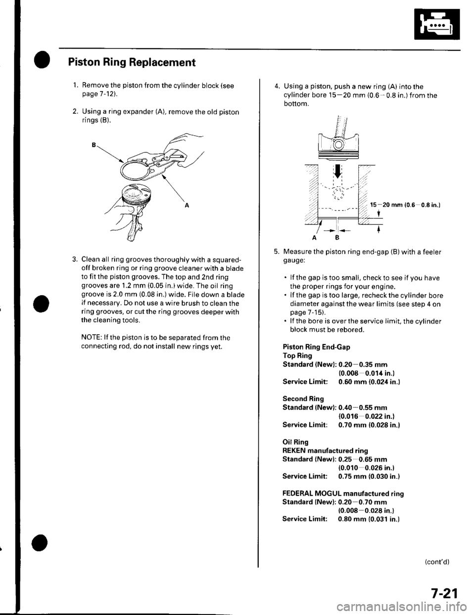
Piston Ring Replacement
1. Remove the piston {rom the cylinder block (see
page 7 -121.
2. Using a ring expander (A), remove the old piston
rings (B).
3. Clean all ring grooves thoroughly with a squared-
off broken ring or ring groove cleaner with a blade
to fit the pislon grooves. The top and 2nd ringgrooves are 1.2 mm (0.05 in,)wide. The oil ringgroove is 2.0 mm (0.08 in.) wide. File down a blade
lf necessary. Do not use a wire brush to clean the
ring grooves, or cut the ring grooves deeper with
the cleaning tools.
NOTE: lf the piston is to be separated from the
connecting rod, do not install new rings yet.
4. Using a piston, push a new ring (A) into the
cylinder bore 15-20 mm {0.6-0.8 in.) from the
bottom.
15 20 mm (0.6 0.8 in.)
I
Measure the piston ring end-gap (B) with a feelerga uge:
. lf the gap istoo small, checkto see if you have
the proper rings for your engine.. lf the gap istoo large, recheckthecylinder bore
diameter against the wear limits (see slep 4 onpage 7-15).. lf the bore is overthe service limit, the cylinder
block must be rebored.
Piston Ring End-Gap
Top Fing
Standard (Newl: 0.20 0.35 mm(0.008 0.014 in.l
Service Limit: 0.60 mm (0.024 in..
Second Ring
Standard (New): 0.40-0.55 mm
{0.016 0.022 in.)
Service Limit: 0.70 mm (0.028 in.)
Oil Ring
REKEN manufactured ring
Standard (Newl: 0.25 0.65 mm(0.010 0.026 in.l
Service Limit: 0.75 mm (0.030 in.)
FEDERAL MOGUL manufactured rino
Standard lNew): 0.20 0.70 mm
{0.008 0.028 in.}
Service Limit: 0.80 mm (0.031 in.)
B
(cont'd)
7-21
Page 160 of 1139

Engine Block
Piston Ring Replacement (cont'd)
6. Install the top ring and second ring as shown.The
top ring (A) has a 1R mark or no mark and the
second ring (B) has a 2R mark or 2ND mark. The
marks must be facing upward.
o\,"16.
s =:-=2
\5
V"
12-)V
P'ffi+a\aq*-pogd
.ZR,
V
Piston Ring oimensions:
t ToP Ring {Standardl:| | o A: 3.1 mm {0.12 in.l
| | J - B:1.2 mm {0.05 in.)Socond Ring {Standard):A:3.4 mm {0.13 in.}- A- B:'1.2 mm (0.05 in.i
7, Rotate the rings in their grooves to make sure they
do not bind.
7-22
\{
8. Position the ring end gaps as shown:
OIL RING GAPAbout 90'SECOND RING GAP
About 45"
OIL RING GAPTOP RING GAPand SPACERRING GAPPISTON PIN
9. After installing a new set of rings, measure the
ring-to-groove clearances:
Top Ring Clearance
Standard {New}:
0.035-0.060 mm {0.0014-0.0024 in.)
Service Limit: 0.13 mm (0.005 in.)
Second Ring Clearance
Standard lNew):
REKEN manutactured ring
0.030-0.055 mm (0.0012-0.0022 in.)
FEDERAL MOGUL manulactured ring
0.025-0.060 mm (0.001 0-0.0024 in.)
Service Limit: 0.13 mm (0.005 in.)
{
Page 161 of 1139

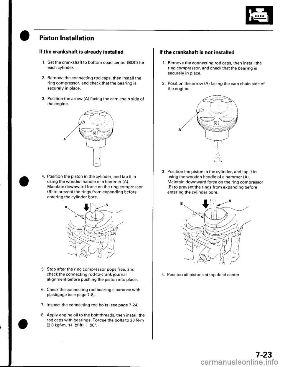
Piston Installation
lf the crankshaft is already installed
1. Setthe crankshaftto bottom dead center (BDC) for
each cylinder.
2. Remove the connecting rod caps, then install the
ring compressor, and check that the bearing is
securely in place,
3. Position the arrow {A) facing the cam chain side of
rne engtne.
Position the piston in the cylinder, and tap it in
using the wooden handle of a hammer (A).
N4aintain downward force on the ring compressor(B) to prevent the rings from expanding before
entering the cylinder bore.
Stop after the ring compressor pops free, and
check the connecting rod-to-crank journal
alignment before pushing the piston into place.
Check the connecting rod bearing clearance withplastigage (see page 7-8).
lnspect the connecting rod bolts (see page 7 241.
Apply engine oil to the bolt threads, then install the
rod caps with bearings. Torque the bolts to 20 N.m
{2.0 kgf m, 14 lbf ft) + 90'.
6.
7.
2.
1.
lf the crankshaft is not installed
Remove the connecting rod caps. then install the
ring compressor, and check that the bearing is
securely in place.
Position the arrow (A)facing the cam chain side of
Ine engrne.
Position the piston in the cylinder, and tap it in
using the wooden handle of a hammer (A),
Maintain downward force on the ring compressor(B) to prevent the rings from expanding before
entering the cylinder bore.
4. Position all pistons attop dead center.
\--lno n\-.--l. ^u t
>-*/zi
.,.'_\pf{
wr
(( 'V,/ :
7-23
Page 162 of 1139
Engine Block
Connecting Rod Bolt Inspection
Measure the diameter of each connectinq rod bolt
at Doint A and ooint B.
35 mm
Calculate the difference in diameter between point
A and point B.
Point A-Point B = Difference in Diameter
Diflerence in Diameter:
Specification: 0 0.1 mm (0 0.004 in.)
lf the difference in diameter is out of tolerance,
replace the connecting rod bolt.
1.
3,
mm
7-24
\-
Crankshaft Installation
Special Tools Bequired. Driver 07749-0010000. Attachment, 24 x 26 mm 07746-0010700. Oil seal driver attachment 96 o7ZAD-PNAAl00
1. Install the crankshaft end bushing with the special
tools when replacing the crankshaft. Drive in the
crankshaft end bushing until the special tools
bottom aqainst the crankshaft.
07749-0010000
07746-00'l
Check the connecting rod bearing clearance with
plastigage {see page 7-8).
Check the main bearing clearance with plastigage
(see page 7-6).
lnspectthe connecting rod bolts (see pageT-241.
(
I\-(
4.
a
Page 163 of 1139

5. Installthe bearing halves in the cylinder block and
conneclrng rods.
6. Apply a coat of engine oilto the main bearings and
rod bearings.
7. Hold the crankshaft so rod journal No.2and rodjournal No. 3 are straight up, and lower the
crankshaft into the block.
8. lnstallthe thrust washers (A) in the No. 4 journal of
the cylinder block.
Apply engine oil to the threads ot the connecting
rod bolts,
Seat the rod journals into connecting rod No. 1 and
connecting rod No. 4. Line up the mark (B) on the
connecting rod and cap, then installthe caps and
bolts finger-tight.
Rotate the crankshaft clockwise, and seat thejournals into connecting rod No.2 and connecting
rod No. 3. Line up the mark on the connecting rod
and cap, then install the caps and bolts finger-tight.
9.
10.
'11 .
\-1
12. Tighten the connecting rod bolts to 20 N.m(2.0 kgf.m, 14 lbf.ft).
13. Tighten the connecting rod bolts an additional 90".
14. Remove old liquid gasket from the lower block
mating surfaces, bolts and bolt holes.
15. Clean and dry the lower block mating surfaces.
16. Apply liquid gasket, P/N 08718-0009, evenly to the
cylinder block mating surface of the lower block
and to the innerthreads ofthe bolt holes.
NOTE: Do not install the parts if 5 minutes or more
have elapsed since applying liquid gasket. Instead,
reapply liquid gasket after removing old residue.
(cont'd)
.\
,i,
Apply liquid gasketalong the broken line.
7-25