Page 548 of 1139
6. Remove the two boot bands (A) from boot (B).
Compress the boot by hand, and apply vinyl tape
(C) so the boot ends stay collapsed and pulled back
Attach the yoke (A) of a universal puller to the
steering gearbox mounts with bolts. Securely
clamp the yoke in a vise as shown. Do not clamp
the steering gearbox housing in the vise.
1.
10.
8. Installthe special tool (A) on the lock screw (B)
securely. then loosen and remove the lock screw
from the steering gearbox housing.
07zAA-S5A0r00
Remove the special tool.
Pull on the rack housing (A) to remove it from the
steering gearbox housing, Remove the boot {B) and
slider guide (C) from the cylinder.
(cont'd)
17-57
Page 549 of 1139
EPS Components
Steering Gearbox Overhaul (cont'd)
'll. Check the slider guide for damage and cracks.Using vernier calipers to measure the thickness ofthe slider guide. lf the thickness is less than servicelimit, replace the slider guide,
f Z,-----:-r-.--------.t.t'E-r
I (fr--', -.----
/i Il il ( t t , ,)))
|i@r
25.3 mm{0.925 in.}
Remove and discard the stop ring {A)on the
cylinder by expanding it with snap ring pliers.
Remove and discard the lock screw {B}.
13. Install the new lock screw on the rack housing.
14. Installthe new stop ring in the groove (C)on thecylinder by expanding it with a snap ring pliers. Becareful not to scratch or damage the housing
surface with the stop ring edges.
25.3 mm{0.925 in.l
12
17-58
15. Apply multipurpose grease to the indicated part
{shaded part) of the outer surface of the rackhousing. Do not apply to the dents and grooves.
\
I
Page 550 of 1139

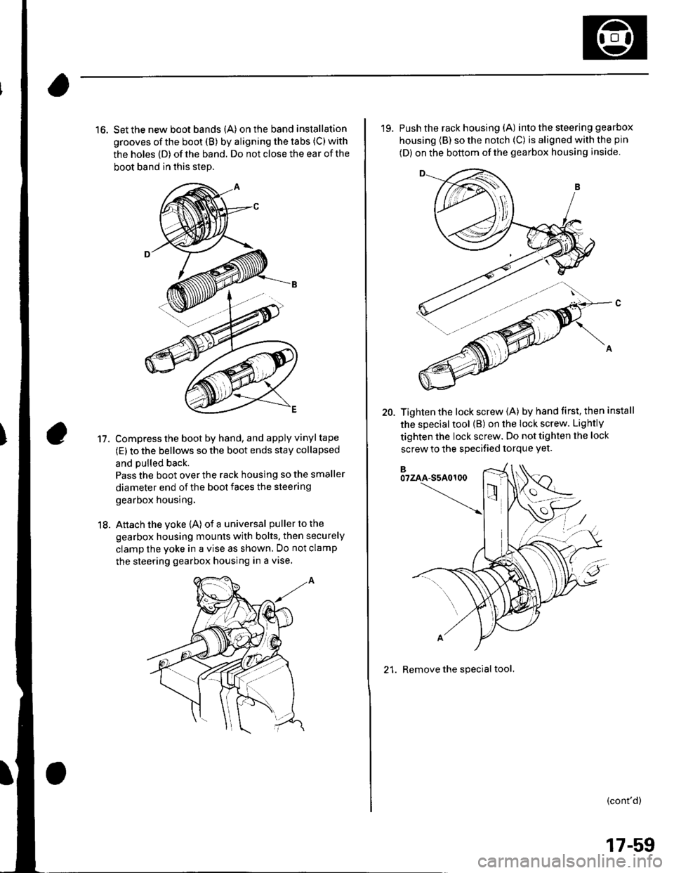
16. Set the new boot bands (A) on the band installation
grooves of the boot (B) by aligning the tabs (C) with
the holes (D) of the band. Do not close the ear of the
boot band in this step.
Compress the boot by hand, and apply vinyl tape
(E) to the bellows so the boot ends stay collapsed
and pulled back.
Pass the boot over the rack housing so the smaller
diameter end of the boot faces the steering
gearbox housing.
Attach the yoke (A) of a universal puller to the
gearbox housing mounts with bolts. then securely
clamp the yoke in a vise as shown. Do not clamp
the steering gearbox housing in a vise.
11.
18.
'19. Push the rack housing (A) into the steering gea rbox
housing (B) so the notch (C) is aligned with the pin
(D) on the bottom of the gearbox housing inside
20. Tighten the lock screw {A) by hand first, then install
the special tool (B) on the lock screw. Lightly
tighten the lock screw. Do not tighten the lock
screw to the specified torque Yet.
21. Remove the special tool.
(cont'd)
17-59
Page 551 of 1139

EPS Components
{Steering Gearbox Overhaul (cont'dl
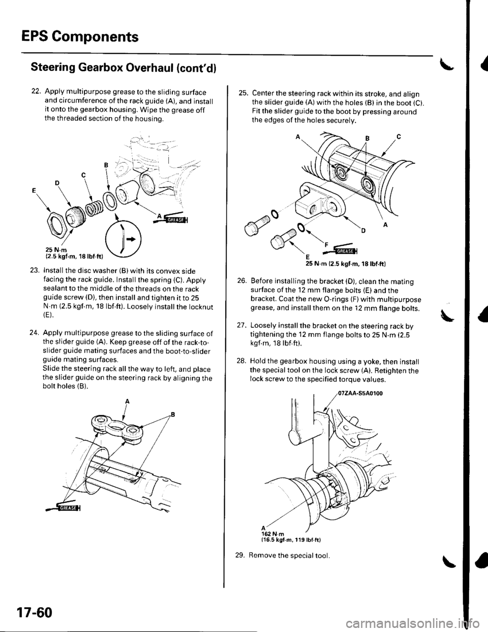
22. Apply multipurpose grease to the sliding surfaceand circumference ofthe rackguide (A), and installit onto the gearbox housing. Wipe the grease offthe threaded section ofthe housrno.
...'.
,. ,l
.j
23. Installthe disc washer (B)with its convex sidefacing the rack guide. Installthe spring (C). Appty
sealant to the middle of the threads on the rackguide screw (D), then install and tighten it to 25
N m (2.5 kgf.m, 18 lbf.ft). Loosely instatlrhe tocknut(E).
24. Apply multipurpose grease to the sliding surface ofthe slider guide (A). Keep grease off of the rack-to-slider guide mating surfaces and the boot-to-sliderguide mating surfaces.
Slide the steering rack all the way to left, and place
the slider guide on the steering rack by aligning thebolt holes (B).
'1 - .- =-1, -
17-60
29.
25. Centerthe steering rack within its stroke, and alignthe slider guide (A)with the hotes (B) in the boot (C).
Fit the slider guide to the boot by pressing around
the edges of the holes securely
E25 N.m 12.5 kgt.m, 18 tbt.ft)
26. Before installing the bracket (D), clean the mating
surface ofthe 12 mm flange bolts (E) and thebracket. Coat the new O-rings {F) with multipurposegrease, and installthem on the '12 mm flange bolts.
27. Loosely install the bracket on the steering rack bytightening the 12 mm flange bolts to 25 N.m (2.5
kgf.m, 18lbf.ft).
28. Hold the gearbox housing using a yoke, then install
the specialtool on the lock screw (A). Retighten thelock screw to the specified torque values.
{16.5 kgt.m, 119 lbf.ft}
Remove the special tool.
A
Page 553 of 1139
EPS Components
Steering Gearbox Overhaul (cont'dl
36. Bend the lock washer against the flat spots on thebracketwith a Iarge pair of pliers.
37. Adjust the rack guide screw {see page 17-13).
17-62
Page 554 of 1139

Steering Gearbox Installation
2.
'1.Before installing the steering gearbox, slide the
rack all the way to the passenger's side (right
direction).
Pass the right side of the steering gearbox together
with the tie-rods through the wheelwell opening on
the passenger's side. Continue moving the steering
gearbox toward the passenger's side untilthe
driver's side tie-rod end and gearbox clears the
master cylinder and under-hood fuse Ielay box.
Lower the steering gearbox. and move it toward
the driver's side untilthe steering gearbox is ln
Dosition.
Be careful not to damage the hoses, lines
and wire harnesses.
3. Installthe pinion shaft grommet (A).
4. Insert the pinion shaft up through the bulkhead,
then slip the right side of the steering gearbox
housing (A) over the mounting stud (C) on the
gearbox mounting bracket.
\- --' '.'', i
10 x '1.25 mm61 N.m{6 2 kgl m, 45 lb{ ftl
Install the steering stiffener B, and lightly tighten
the steering gearbox mounting nuts.
Install the steering stiffener A with the gearbox
mounting bolts. Then tighten allthe steering
gearbox mounting hardware to the specified torque.
10 x 1.25 mm6l N.m(6.2 kgt.m, 45 lbt.ft)
: --.-{..
(cont'd )
:-1....
17-63
Page 555 of 1139
EPS Components
Steering Gearbox Installation (cont'd)
7. Installthe body stiffener (A), and torque the
mounting bolts to the specified torque.
8 x 1.25 mm29 N.m {3.0 kgf.m,22lbf.ftl
LInstall the heater valve (A) on the bulkhead, and
connect the heater valve cable end (B) to the heater
valve arm (C). Readjust the heater valve cable {seepage 21-46).
9.8 N.m(1.0 kgf m,7.2 tbf.ftl
L-t ,:.i.t'
17-64
9. Reinstall the heater hose (A) on the hose bracket.
Install the engine wire harness clamps (B) to the
three harness brackets.
Under the steering gearbox, install the ground
cable terminal (A) on the steering gearbox housing.
10.
'I t.
9.8 N.m{1.0 kgf.m, 7.2lbf.ft)
Page 556 of 1139
12. lnstallthe EPS wire harness bracket (A) on the
gearbox housing, and connect the 6P connector (B)
propefly.
9.8 N.m{1.0 kgt m,7.2 lbt.ftl
13. Installthe heat shield (A).
,.!,..''6f
14.
15.
Center the steering rack within its stroke.
Wipe off any grease contamination from lhe ball
joint tapered section and threads. Then reconnect
the tie-rod ends 1A)to the damper steering arms.
lnstall the ball joint nut (B) and tighten them.
Install the new cotter pins (C), and bend them as
shown.
(cont'd)
B10 x 1.25 mmi€ N.m{4.4 kgf.m.32 tbt.ftl
to.
, -', ''l
:1)
17-65