2002 HONDA CIVIC lights
[x] Cancel search: lightsPage 925 of 1139

Interior Lights
uJComponent Location Index
CEILING LIGHT/SPOTLIGHTSTest, page 22-96Replacement, page 22-96
REAR CEILING LIGHTTest, page 22-96Replacement, page 22-96
vJ
HATCH LATCH SWITCHTest, page 22-97
CARGO AREA LIGHTfesl, page 22-97Replacement, page 22-97
22-94
$J
Page 927 of 1139

Interior Lights
Ceiling Light/Spotlights Test/
Replacement
Turn the ceiling lighvspotlights switches OFF.
Carefully pry off the lens {A) wilh a small
screwdnver,
Ceiling Light: 5W
Spotlight: 5Wx2
1.
2.
x 1-0 mm
3. Remove the two screws and the housing (B).
4. Disconnect the 4P connector (C) fromthehousing.
5. Check for continuity between the terminals in each
switch position according to the table.
\A
Terminal
P."lil;- -----_lil
celL,"c a,c", oFF
isoottiohts MIDDLE'uir oN
re-o
a}-+4-o
SPOTLIGHTS
I Ceilinq liohtroFF-- i
RONo(.F.O
OFF
LONG-
OFF
lf the continuity is not as specified, check the bulb.lf the bulb is OK, replace the ceiling lighvspotlig hts.
22-96
1.
2.
3.
4.
Rear Ceiling Light Test/
Replacement
Turn the light switch OFF.
Carefully pry offthe lens (A) with a small
screwdriver.
Ceiling Light: 8 W
5x1.0mm
A.
Remove the two mounting screws.
Disconnect the 3P connector (B) from the housing
{c).
Check for continuity between the terminals in each
switch position according to the table.
Terminal
Position123
OFF
MIDDLEo
ONG-@-O
lf the continuity is not as specified, check the bulb.
lf the bulb is OK, replace the rear ceiling light.
Page 987 of 1139

Keyless/Power Door Lock System
Control Unit Input Test (cont'dl
5. Reconnect all connections to the underdash fuse/relay box, and make these input tests at the appropriate connectors on the under-dashfuse/relay box.
'lfanytestindicatesaproblem,findandcorrectthecause,thenrecheckthesystem.. lf all the inputtests prove OK, goto step 6.
CavitvWireTest conditionTest: Desired resultPossible ca use if result is notobtainedc1'l8LUUnder all conditionsAftach to ground:Parking, side marker, licenseplate lights, and tajllights shouldcome on.
Blown No.2 (15A)fuse in the underhood fuse/relay boxFaulty taillight relayFaulty under-dash fuse/relay boxAn onen in rhc wireBLU/BEOUnder all conditionsAttach to ground:Headlights should come on.Blown No. 15 or 17 (15A)fuse in theunderhood fuse/relay boxFaulty headlight relay '1 or 2An ooen in the wireJ2WHT/REDUnder all conditionsCheck for voltage to ground:There should be battery voltage.Blown No.9 (15A)fuse in the under-hood fuse/relay boxAn oncn in thc wircBLKUnder all conditaonsCheck for voltage to ground:Thcre shouln hc 1 V or lpqsPoor ground (G501)An ooen in the wireJ6OBNUnder allconditionsAttach to ground:The horns should sound.Blown No. 7 (15A)fuse in the underhood fuse/relay boxFaulty horn relayFaulty hornsAn 6nen in rhe wireJ7Under all conditionsCheck for voltage to ground:There should be battery voltage.Elown No. 16 (20A)fuse in the underhood fuse/relay boxAn oocn in ihc wi.cP18BEDHatch openCheck for voltage to ground:There should be 1 V or less.Poor ground (G552)Faulty hatch latch switchAn oncn in rhc wirFHatch closedCheck for voltage to groundlThere shoul.l he 5 V or moreFaulty hatch latch switch
GBNDriver's door openCheck for voltage to g.ound:There should be 1 V or less. Faulty driver's door switch. An ooen in the wireDriver's door closedCheck for voltage to ground:There should be 5 V or more.Faulty driver's door switchShort to oroundo4LT GRN/REDPassenger's door openCheck for voltage to ground:There should be 1 V or less.Faulty passenger's door switchAn ooen inthewirePassenger's door closedCheck for voltage to groundlThere should be sVor more
. Faulty passenger's door switch. Short to oroundX5REDAVHTlgnition key inserted intothe ignition swhchCheck for voltage to ground:There should be 1 V or less.Poor ground {G401)Faulty ignition key switchAn ooen inthewirelgnition key removed fromrhe ionition switchCheck for voltage to ground:There should be 5 V or more.Faulty ignition key switchShort to oroundY1WHT/BLKDriver's door lock knobswitch unlockedCheck for voltage to groundlThere should be 1 V or less.Poorground (G50'l)Faulty driver's door lock knob switchAn open in the wireDriver's door lock knobCheck for voltage to groundlIhere should be 5 V or more.Faulty driver's door lock knob switchShort to oroundY8YEUREDDriver's door lock knobswitch lockedCheck for voltage to groundlThere should be 1 V or less.Poorground (G50'l)Faulty driver's door lock knob switchAn oncn inihewireDriver's door lock knobswitch unlockedCheck for voltage to ground:There should be 5Vor more' Faulty driver's door lock knob sw;tch. Shorr to oroundY10WHT/GRNDrtver's door lock switchunlockedCheck for voltage to groundlThere should be 1 V or less.Poorground (G501iFaulty driver's door lock switchAn ooen in the wireDriver's door lock switch inCheck for voltage to ground:Therc shorl.l be 5V or m6rpFaulty driver's door lock switchShort to o rolrndY12WHT/BLUDriver's door lock switchlockedCheck for voltage to ground:There should be 'l V or less.Poor ground (G501)Faulty driver's door lock switchAn oDen in the wireDriver's door lock switch inCheck tor voltage to ground:There should be 5Vor moreFaulty driver's door lock switch
22-156
J
Page 999 of 1139

Multiplex Control System
Component Location Index
IGNITION KEY LIGHTTest, page 22'91
lr, J
REAR CEILING LIGHTTest, page 22'96
LIGHT/SPOTLIGHTSTest, page 22-96
GAUGE ASSEMBLY
ECM
MULTIPLEX CONTROL UNIT{Built into the under-dashfus6/relav boxlTroubleshooting, page 22'172Input Test, page 22-175
22-168
t
Page 1002 of 1139

ISystem Descriptions
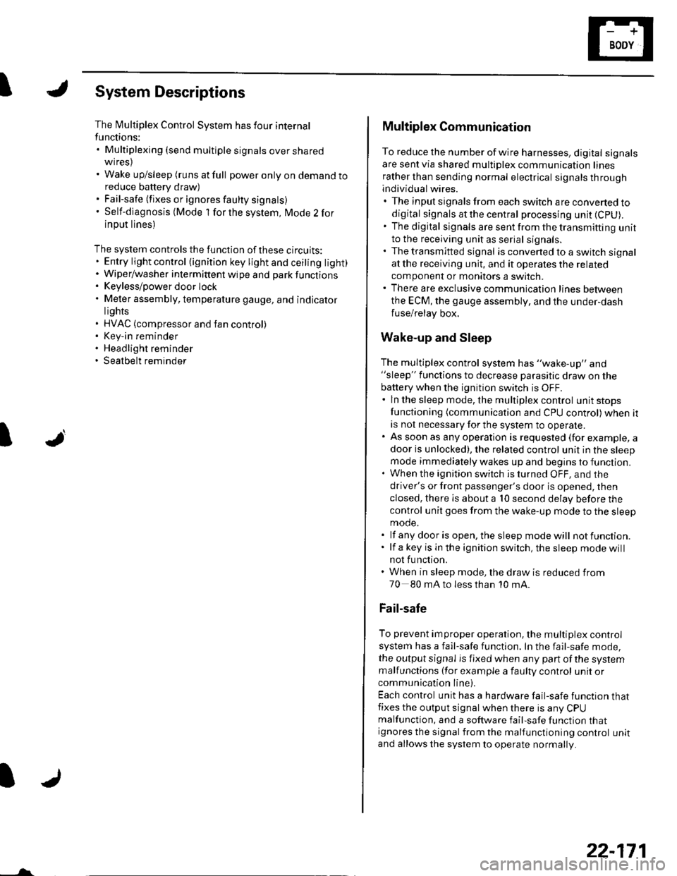
The Multiplex Control System has four internal
functions:. Multiplexing (send multiple signals over sharedwtres). Wake up/sleep (runs at full power only on demand toreduce battery draw). Fail-safe (fixes or ignores faulty signals). Self-diagnosis (Mode 1 for the system, Mode 2 for
input lines)
The system controls the function of these circuits:. Entry lightcontrol (ignition key lightandceiting light). Wiper/washer intermittent wipe and park functions. Keyless/power door lock. Meter assembly, temperature gauge, and indicator
lights. HVAC (compressor and fan control). Key-in reminder. Headlight reminder. Seatbelt reminder
JI
/ar
22-171
Multiplex Communication
To reduce the number of wire harnesses, digital signals
are sent via shared multiplex communication linesrather than sending normal electrical signals throughindividual wires.. The input signals from each switch are converted todigital signals at the central processing unit (CpU).. The digital signalsaresentfromthetransmitting unitto the receiving unit as serial signals.. The transmitted signal is converted to a switch signalat the receiving unit, and it operates the related
component or monitors a swltch.. There are exclusive communicalion lines between
the ECM, the gauge assembly, and the under,dash
fuse/relay box.
Wake-up and Sleep
The multiplex control system has "wake-up" and"sleep" functions to decrease parasitic draw on the
battery when the ignition switch is OFF.. ln the sleep mode, the multiplex control unit stops
functioning (communication and CPU control) when it
is not necessary for the system to operate.. As soon as any operation is requested (for example, adoor is unlocked), the related control unit in the sleep
mode immediately wakes up and begins to function.. When the ignition switch is turned OFF, and the
driver's or front passenger's door is opened, then
closed, there is about a 10 second delay before the
control unit goes from the wake-up mode to the sleepmode.. lf any door is open, the sleep mode will not function.. lf a key is in the ignition switch, the sleep mode will
not function.. When in sleep mode, the draw is reduced from
70 80 mA to less than 10 mA.
Fail-safe
To prevent improper operation, the multiplex controlsystem has a fail-safe function. In the fail-safe mode,
the output signal js fixed when any part of the systemmalfunctions (for example a faulty control unit orcommunication line).
Each control unit has a hardware fail-safe function thatfixes the output signal when there is any CPUmalfunction, and a software fail-safe function thatignores the signal from the malfunctioning control unitand allows the system to operate normally.
Page 1008 of 1139

IJ
IJ
IJ
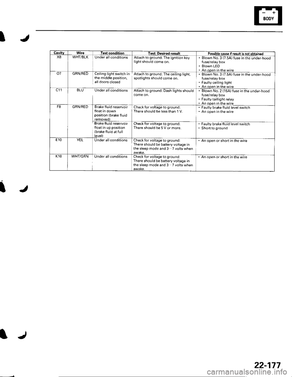
CavitvWireTest conditionTest: Desired resultPossible cause if resuk is not obtainedX8WHT/BLKUnder allconditionsAttach to ground:The ignition keylight should come on.Blown No.3 (7.5A)fuse in the under,hood
Blown LEDAn ooen in the wireo7GRN/REDCeiling light switch inthe middle position,all doors closed
Attach to ground:The ceiling light,spotlights should come on.Elown No. 3 (7.54)fuse in the undeFhood
Faulty ceiling lightAn oDen in the wirec]1BLU Under all conditionsAttach to ground: Dash lights shouldBlown No. 2 (15Aifuse in the under-hoodfuse/relay boxFaulty taillight relayAn ooen in the wireF8GRN/REDBrake fluid reservoirfloat in downposition (brake fluid
Check for voltage to ground:There should be less than I V.Faulty brake fluid level switchAn open in the wire
Brake lluid reservoirfloat in up position(brake fluid at fulllevel)
Check for voltage to ground:There should be 5 V or more.Faulty brake fluid level switchShortto ground
E10YELUnder all conditionsCheck for voltage to ground:There should be battery voltage inthe sleep mode and 3 Tvoltswhen
. An open or short in the wire
K10WHT/GRNUnder all conditionsCheck for voltage to ground:There should be battery voltage inthe sleep mode and 3 Tvoltswhen
An open or short in the wire
22-177
Page 1026 of 1139

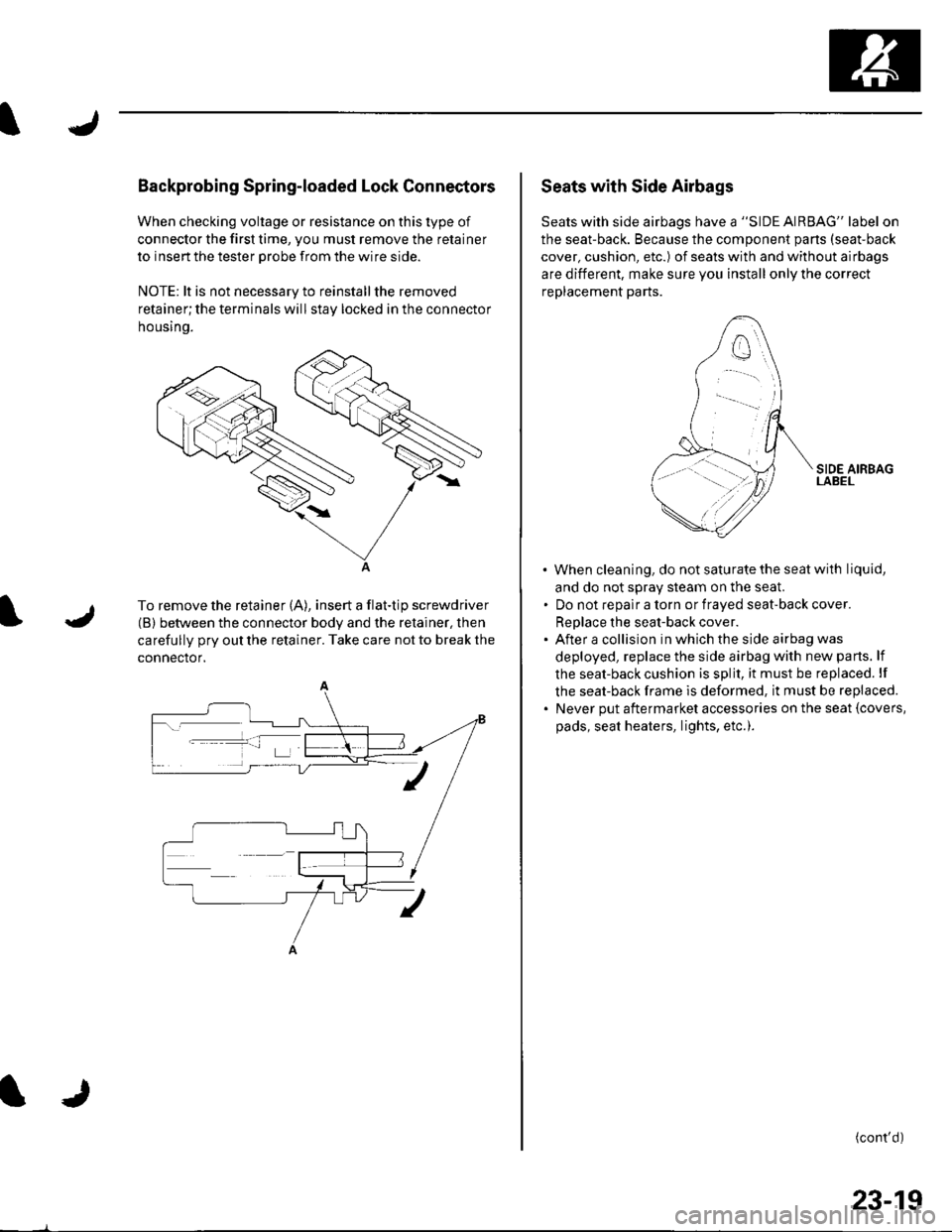
Backprobing Spring-loaded Lock Connectors
When checking voltage or resistance on this type of
connector the first time, you must remove the retainer
to insert the tester orobe from the wire side.
NOTE: lt is not necessary to reinstall the removed
retainer;the terminals will stay locked in the connector
housrno.
A
To remove the retainer (A), insert a flat-tip screwdriver
(B) between the connector body and the retainer, then
carefully pry out the retainer. Take care not to break the
connector.
Seats with Side Airbags
Seats with side airbags have a "SIDE AIRBAG" label on
the seat-back. Because the component pans (seat-back
cover, cushion, etc.) of seats with and without airbags
are different, make sure you install only the correct
replacement parts.
When cleaning, do notsaturatethe seatwith liquid,
and do not sDrav steam on the seal
Do not reoalr a torn or fraved seat-back cover.
ReDlace the seat-back cover.
After a collision in which the side airbag was
deployed, replace the side airbag with new parts. lf
the seat-back cushion is split, it must be replaced. lf
the seat-back frame is deformed, it must be replaced.
Never put aftermarket accessories on the seat {covers,
pads, seat heaters, lights, etc.).
(cont'd)
23-19
Page 1111 of 1139

sRs
DTG Troubleshooting (cont'dl
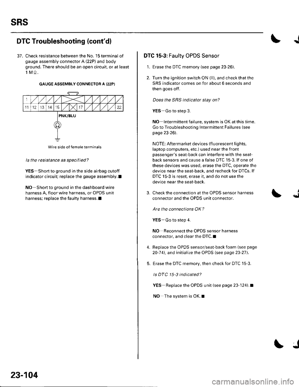
37. Check resistance between the No. 15 terminal of
gauge assembly connector A (22P) and body
ground. There should be an open circuit, or at least
1M0.
GAUGE ASSEMBLY CONNECTOR A I22PI
ls the resistance as specified?
YES-Short to ground in the side airbag cutoff
indicator circuit; replace the gauge assembly.l
NO Short to ground in the dashboard wire
harness A, floor wire harness, or OPDS unit
harness; replace the faulty harness.l
Wire side of female terminals
23-104
J
DTC 15-3: Faulty OPDS Sensor
1. Erase the DTC memory {see page 23-261.
2. Turn the ignition switch ON (ll), and check that the
SRS indicator comes on for about 6 seconds and
then goes off.
Does the SRS indicator stay on?
YES-Go to step 3.
NO Intermittent failure, system is OK at this time.
Go to Troubleshooting Intermittent Failures (see
page 23-26).
NOTE: Aftermarket devices (fluorescent lights,
laptop computers, etc.) used near the front
passenger's seat-back can interfere with the seat-
back sensors and cause a false DTC 15-3. lf one of
these devices was used, erase the DTC, operate the
device near the seat-back, and recheck for DTCs. lf
DTC 15-3 is reset, erase it, and do not use the
device near the seat-back.
3.
4.
Check the connection at the OPDS sensor harness
connector and the OPDS unit connector.
Are the connections OK?
YES-Go to step 4.
NO Reconnect the OPDS sensor harness
connector, and clear the DTC.I
Replace the OPDS sensor/seat-back foam (see page
20-141, and initialize the OPDS (see page 23-27).
Erase the DTC memory, then check for DTC 15-3.
ls DTC 15-3 indicated?
YES Replace the OPDS unit (see page 23-1241.a
NO The system is OK.l
{