Page 604 of 1139
GRN/ORN
,tk ,o"","o ""o*.(b, 3s1E8,.""",,"
I oPEN,Leve,down
I-=:
I
A
YBtK
+csor
Brake System Indicator Circuit Diagram
UNDER.OASHFUSE/FELAYBOX
EBAK€FLUIDIEVELSwlICH
19-9
Page 623 of 1139
Brakes
Conventional Brake Components ................ 1 9-1
ABS (Anti-lock Brake System) Components
Comoonent Location lndex .............,........................... 19-30
General Troubleshooting Information ....................... 19-31
DTC Troubleshooting Index .............. 19-34
Symptom Troubleshooting Index ...,........................... 19-35
System Description ................. ........... 19-36
Circuit Diagram ......... 19-42
DTC Troubleshooting ............... .......... 19-45
ABS Indicator CircuitTroubleshooting ...................... 19-52
Brake System Indicator Circuit
Troubleshooting ...................... ....... 19-55
ABS Modulator-Control Unit Removal and
lnstallation ............. 19-57
Wheel Sensor Insoection ................... 19-59
Wheel Sensor Reolacement .............. 19-59
Page 636 of 1139
ABS Gomponents
Circuit Diagram
L "*'*" lJ I5l
r**'t?lI r+l
I ^ lo+-sN
Gu csl LqF**,
"'-----
G50l
19-42
Page 638 of 1139
ABS Components
q,
CONNECTOR A {12P)BRAKE PEDAL POSITIONSWITCH 4P CONNECTOR
Circuit Diagram (cont'd)
UNDER-HOOD FUSE/RELAY BOX CONNECTORSCONNECTOR A {12P) CONNECTOR B {2P}
UNDER.DASH FUSE/RELAY BOX CONNECTORSCONNECTOR I {5P)CONNECTOR K I17P)MULTIPLEX CONTROLUNIT 13P CONNECTOR
CONNECTOR B I22PI
1l2l3l,/15
GAUGE ASSEMBLY CONNECTORS
CONNECTOR A I22P)
WHEEL SENSOR 2P CONNECTORS
FRONT
J --T:-l Ltqtt/)l'l L_.:-:J r\-r-----Tr'e:l
RIGHT.REAR LEFT-REAR
tslTt?t /J 1T-1\I tL | rlziJ
Terminal side of male lerminals
ABS CONTROL UNIT 3IP CONNECTOR
OATA LINK CONNECTOR {16P)
Terminal side of female terminals
Wire side of female terminals
1234567
810111213141511
123,/ ,/
67891011n213
1245678I11121415
161118192021/1,/1,/vl,/l
/t,/t/t,/t/
19-44
Page 773 of 1139

21-2
z t-'5
z t-o
z t-o
21-8
21-9
21-10
21-11
21-14
z t- to
HVAC (Heating, Ventilation, and Air Gonditioningl
Heating and Air Conditioning
SpecialTools
Comoonent Location lndex ........
A/C Service Tios and
Precautions
A,/C Refrigerant Oil
ReDlacement
General Troubleshooting
lnformation
DTC Troubleshooting Index .......
Symptom Troubleshooting
1ndex..............
System Description .....................
Circuit Diagram
DTC Troubleshooting ..................
Recirculation Control Motor
CircuitTroubleshooting .......... 21-25
Heater Control Power and Ground
Circuits Troubleshooting ........ 21-27
Condenser Fan Circuit
Troubleshooting ...................... 21-28
Radiator and Condenser Fans
Common Circuit
Troubfeshooting ...................... 21-29
Compressor Clutch Circuit
Troubleshooting ...................... 21-30
A,/C Pressure Switch Circuit
Troubleshooting ...................... 21-32
Air Mix Control Motor
Test and Reolacement ............. 21-34
Mode Control Motor
Test and Replacement ............. 21-35
Recirculation Control Motor
Test and Reolacement ............. 21-36
Evaporator Temperature Sensor
Reolacement and Test ............. 21-31
Power Transistor Test ................. 21 -38
Heater Control Panel and
Push Switch Assemblv
Removal and Installation ........ 21-38
Dust and Pollen Filter
Reolacement ..21-39
Blower Unit Removal and
lnstallation ...... 21-39
Blower Unit Comoonents
ReDlacement ............................ 21-41
Evaporator Core
Reolacement ..21-42*Heater Unit/Core
ReDlacement ..21-43
Heater Valve Cable
Adjustment .....21-46
CompressorReplacement .......... 21-47
Comoressor Clutch Check .......... 21-48
Comoressor Clutch Overhaul ..... 21-49
Compressor Thermal Protector
Reo1acement ............................ 21-51
Comoressor Relief Valve
Reolacement ............................ 21-51
Condenser Reolacement ............ 21-52
Refrigerant Recovery .................. 21-53
System Evacuation ...................... 21-54
System CharginS ......................... 21-55
Refrigerant LeakTest .................. 21-56
A,/C Svstem Tests ........................ 21-57
Page 785 of 1139
Heating and Air Conditioning
Gircuit Diagram
UNDEN rcODFUSVRELIYSOXUNOER DASNfUSE/8EIlYBOX|GNUION SWTCfilG2 HoI ii 0l\l llll
+. C}F BLK/RED rG2 /
II
I
I
In.G301
A/C PnESSUEtswTOt
t...iCF
RADIATOS
oT0n
NADIATOS) tAl'// swtlcllj 19S"F 193"C) l
CONDEN$N
MOTOB
I8u(
I
IBLX
I
G301
l
;
/ .I IHEFMAI
Y PBorEcro8
lTl *n*,*,|
_l
MUITIPLD(CONTFOIUNITI
-!10. irgF 8Ll
TT
BLU
I ilntho undor dasi luse/lelay box
21-14
Page 831 of 1139

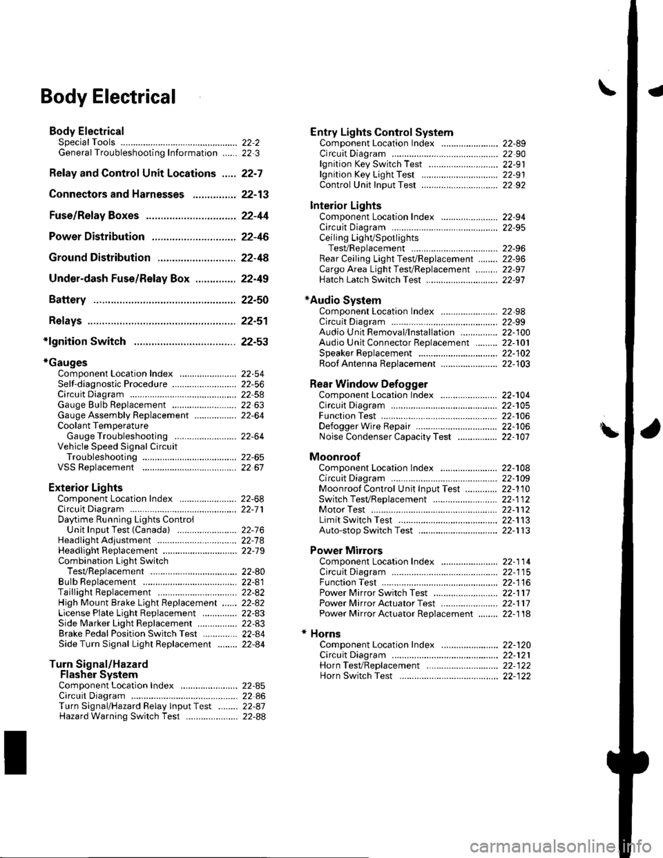
\Body Electrical
Body ElectricalSpecialToolsGeneral Troubleshooting tntorrnaiion.'......
Relay and Control Unit Locations .....
Connectors and Harnesses
Fuse/Relay Boxes ...............................
Power Distribution .............................
Ground Distribution ...........................
Under-dash Fuse/Relay Box ..............
Battery ..............
Relays ................
*lgnition Switch ..............
*Gauges
Component Location Index .......................Self-diagnostic Procedure ..........................Circuit DiagramGauge Bulb Replacement ..........................Gauge Assembly ReplacementCoolant Temperature
Gauge Troubleshooting .... ....................Vehicle Speed Signal CircuitTroubleshootingVSS Replacement
Exterior LightsComponent Location Index .......................Circuit DiagramDaytime Running Lights ControiUnit Input Test (Canada) ........................Headlight Ad,ustment .................. .. .....Headlighr Replacement ..............................Combination Light SwitchTest/ReplacementBulb ReplacementTaillight Replacement ..........................High Mount Brake Light Replacement ......License Plate Light Replacement ..............Side Marker Light Replacement ................Brake Pedal Position Switch Test ..............Side Turn Signal Light Replacement ........
Turn Signal/HazardFlasher SystemComponent Location Index .......................Circuit DiagramTurn Signal/Hazard Relay lnputTest ........Hazard Warning Switch Test
22,3
22-7
22-13
22-44
22-46
22-4A
22-49
22-50
22-51
22-53
22-5422-5622-5422 6322-64
22-64
22-6522 61
22-6822--71
22-7 622-7422-79
22-AO22-4122-8222-4222-4322-4322-4422-84
22-8�522 A622-8722-88
22-10422-105
22-10622-107
Entry Lights control systemComponent Location Index ....................... 22-89Circuit Diagram ......... 22 90lgnition Key Switch Test .....................,...... 22-9'llgnition Key Light Test ............................... 22-91Control Unit Input Test ..........,.................... 22 92
Interior LightsComponent Location Index ....................... 22-94Circuit Diagram ......... 22-95Ceiling LighVSpotlightsTesVReplacement ................................... 22-96Rear Ceiling Light TesVReplacem ent ........ 22-96Cargo Area Light Test/Replacem ent ......... 22-97Hatch Latch Switch Test ..,..,....................... 22-97
*Audio SystemComponent Location Index ....................... 22-98Circuit Diagram ......... 22,99Audio Unit Removal/lnstallation ............... 22-1OOAudio Unit Connector Replacement ......... 22-101Speaker Replacement ................................ 22-102Roof Antenna Rep1acement ....................-.. 22-103
Rear Window DefoggerComponent Location Index ...........Circuit Diasram .. ....... .. ..... ....... ...:::::.::.::.Function TestDefogger Wire Repair .................................Noise Condenser CapacityTest ................
MoonroofComponent Location Index ....................... 22-1OBCircuit Diagram ......... 22-109Moonroof Control Unit Input Test ............. 22-'l10Switch TesVReplacement ........,.....,........... 22-1 12Motor Test ................. 22-112Limit Swilch Test ...... 22-'l'13Auto-stop Switch Test ................................ 22-1 13
Power MirrorsComponent Location Index ....................... 22-114Circuit Diagram ......... 22-115Function Test ............. 22-116Power Mirror Switch Test .......................... 22-ll7Power Mirror Actuator Test ....................... 22-117Power Mirror Actuator Replacement ........ 22-11A
* HornsComponent Location Index ....................... 22-120Circuit Diagram ......... 22-121Horn TesVReplacement ...........................-. 22-122Horn Switch Test .,.... 22-122
\
Page 832 of 1139

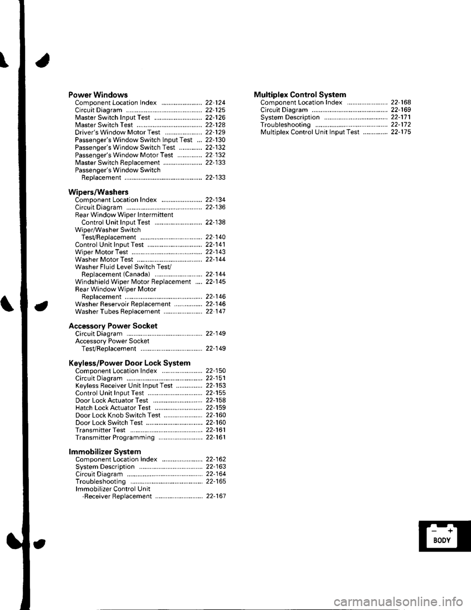
Power WindowsComponent Location Index ..........
circuit Diagram . .. ............... .........:.::::.::::.:Master Switch Input Test ...........................Master Switch TestDriver's Window Motor Test .....................
Passenger's Window Switch lnput Test ...Passenger's Window Switch Test .............
Passenger's Window Motor Test ..............
lMaster Switch Replacement ......................
Passenger's Window SwitchReplacement
Wipers/WashersComponent Location Index .......................
Circuit DiagramRear Window Wiper Intermiftent
Control Unit Input Test ...........................Wiper/Washer SwitchTesVReplacementControl Unit Input Test ...............................Wiper Motor Test
Washer Motor TestWasher Fluid Level Switch TesV
Replacement (Canadal ..........................
Windshield Wiper Motor Replacement ....
Rear Window Wiper MotorReplacementWasher Reservoir Replacement ................
Washer Tubes Beplacement ......................
Accessory Power SocketCircuit Diagram ......... 22-149
Accessory Power Socket
TesVReplacement ................................... 22-1 49
Keyless/Power Door Lock System
Component Location Index ....................... 22-150
Circuit Diagram ......... 22-151Keyless Receiver Unit InputTest ............... 22-153
Control Unit Input Test ............................... 22-155
Door LockActuatorTest .........,.......,..,.,..... 22-158Hatch LockActuatorTest ........................... 22-159
Door Lock Knob Switch Test ...................... 22-160
Door Lock Switch Test ................................ 22-160
Transmitter Test ....... 22-161
Transmitter Programming ......................... 22-161
Multiplex Control SystemComponent Location Index ...........
circuit Diagram ...... ........................::.:..:.::.:
Svstem DescriDtionTroubleshootingMultiolex Control Unit InDut Test .............
22 12422-12522-12622-12822-129
22- t30
22-13222 13222-133
22-133
22-134
22-138
22-14022-14122-14322-144
22-14422-145
22-14622-14622 147
22,16422-16922-17'l22,11222-175
lmmobilizer Systemcomponent Location Index ...........
System Description ....... ............. ..:..:..:.:...
Circuit DiagramTroubleshootinglmmobilizer Control Unit-Receiver Replacement ...........................
22-16222-16322-164
22-167