Page 238 of 1139
System Diagram
INTAKE
CMP SENSOR A
BRN/YELBLU/WHT
BLU/WHT
BLK/WHT
GRN/YEL
BLU/BLK
From No. ilACC {10A) fuse
VARIOUSSENSORS
CAMSHAFT -:-
BLK
It
Camshaft Position {CMP} Sensor
The CMP sensor detects camshaft angle position for the VTC system.
{cont'd}
11-31
:5i.T,""
Page 239 of 1139

Fuel and Emissions Systems
(
{
System Descriptions (cont'd)
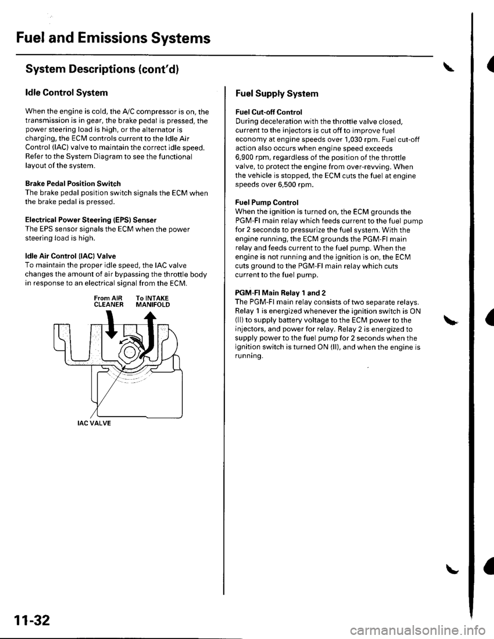
ldle Control System
When the engine is cold, the Ay'C compressor is on, the
transmission is in gear, the brake pedal is pressed. thepower steering load is high, or the alternator is
charging, the ECIM controls current to the ldle Air
Control (lAC) valve to maintain the correct idle speed.
Refer to the System Diagram to see the functional
layout of the system.
Brake Pedal Position Switch
The brake pedal position switch signals the ECM when
the brake pedal is oressed.
Electrical Power Steering (EPS) Senser
The EPS sensor signals the ECM when the power
steering load is high.
ldle Air Control llACl Valve
To maintain the proper idle speed, the IAC valve
changes the amount of air bypassing the throttle body
in response to an electrical signal from the ECM.
From AIR To INTAKECLEANER MANIFOLD
IAC VALVE
11-32
Fuel Supply System
Fuel Cut-off Control
During deceleration with the throttle valve closed,
current to the injectors is cut off to improve fuel
economy at engine speeds over 1,030 rpm. Fuel cut-off
action also occurs when engine speed exceeds
6,900 rpm, regardless of the position of the throttle
valve, to protect the engine from over-rewing. When
the vehicle is stopped. the ECM cuts the fuel at engine
speeds over 6,500 rpm.
Fuel Pump Control
When the ignition is turned on, the ECM grounds the
PGM-Fl main relay which feeds current to the fuel pump
for 2 seconds to pressurize the fuel system, With the
engine running. the ECM grounds the PGM-Fl main
relay and feeds current to the fuel pump. When the
engine is not running and the ignition is on, the ECI\4
cuts ground to the PGM-Fl main relay which cuts
current to the fuel pump.
PGM-FI Main Relay 1 and 2
The PGM-Fl main relay consists of two separate relays.
Relay 1 is energized whenever the ignition switch is ON(ll) to supply battery voltage to the ECM power to the
injectors, and power for relay, Relay 2 is energized to
supply power to the fuel pump for 2 seconds when the
ignition switch is turned ON (ll), and when the engine is
runnrng.
Page 240 of 1139
Intake Air System
Refer to the System Diagram to see the functional
layout of the system.
Intake Air Bypass Control Thermal Valve
When the engine is running, the intake air bypass
control thermal valve sends air to the iniectors,
INJECTOR
Throttle Body
The throttle body is a single-barrel side draft type. lt
houses the TP senser and the IAC valve. The lower
portion of the IAC valve is heated by engine coolant
from the cylinder head.
IAC VALVE
{cont'd)
11-33
Page 242 of 1139

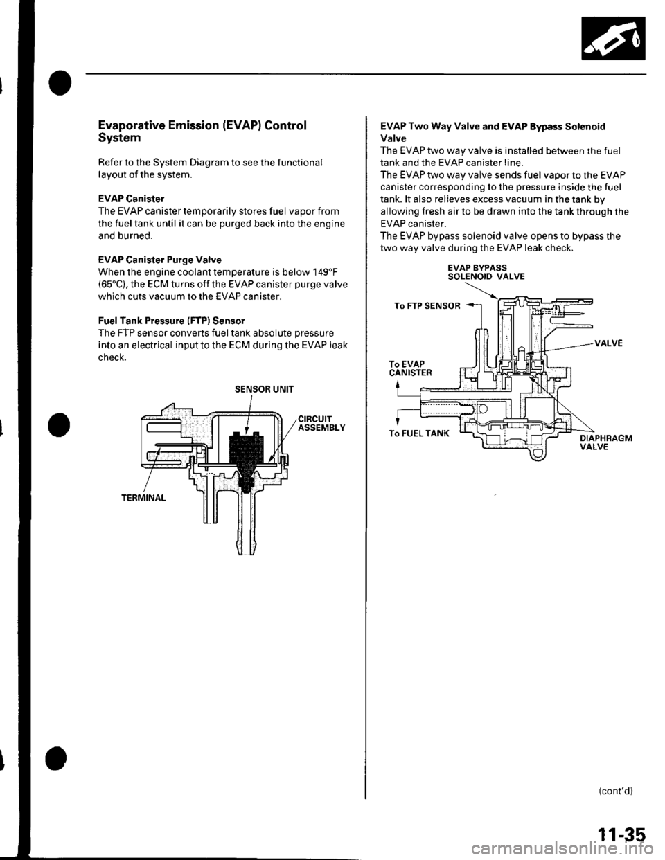
Evaporative Emission (EVAPI Control
System
Refer to the System Diagram to see the functional
layout of the system.
EVAP Canister
The EVAP canister temporarily stores fuel vapor from
the fuel tank until it can be purged back into the engine
and burned.
EVAP Canister Purge Valve
When the engine coolant temperatu re is below 149'F(65'C), the ECM turns off the EVAP canister purge valve
which cuts vacuum to the EVAP canister.
FuelTank Pressure (FTP) Sensor
The FTP sensor converts fueltank absolute pressure
into an electrical inputto the ECM during the EVAP leak
cnecK.
SENSOR UNIT
EVAP Two Way Valve and EVAP Eyp8s Solenoid
Valve
The EVAP two way valve is installed between the fuel
tank and the EVAP canister line.
The EVAP two way valve sends fuel vapor to the EVAP
canister corresponding to the pressure inside the tuel
tank. lt also relieves excess vacuum in the tank by
allowing fresh air to be drawn into the tank through the
EVAP canister.
The EVAP bypass solenoid valve opens to bypass the
two way valve during the EVAP leak check.
EVAP BYPASSSOLENOID VALVE
VALVE
(cont'd)
To FUEL TANK
11-35
Page 243 of 1139
Fuel and Emissions Systems
System Descriptions (cont'dl
ldle Control System Diagram
The idle speed of the engine is controlled by the ldle Air Control (lAC) varve:
'Aftertheenginestarts,theIACvalveopensforacertainamountoftime.Theamountofairisincreasedtoraisethe
idle sDeed.. When the engine coolant temperature is low, the IAC valve is opened to obtain the proper fast idle speed. Theamount of bypassed air is controlled in relation to engine coolant temperature.
INTAKE MANIFOLDIAC VALVEAKE AIR DUCT
CLEANER
\
BLK/REO
YEL/BLK ---< FromPGM.FIMAINRELAY
THROTTLE AODY
Intake Air System Diagram
This system supplies air for engine needs. A resonator in the intake air
drawn into the svstem.
VARIOUSSENSOnS
pipe provides additional silencing as air is
THROTTLE AODYVARIOUSSENSORS
BLK
BLK
I
11-36
{
Page 244 of 1139

Evaporative Emission (EVAPI Control Diagram
The EVAP controls minimize the amount of fuel vapor escaping to the atmosphere. Vapor from the fuel tanK rstemporarily stored in the EVAP canister until it can be purged from the canister into the engine and burneo.
. The EVAP canister is purged by drawing fresh air through it and into a port on the intake manifold.The purging vacuum is controlled by the EVAP canister purge valve, which operates whenever engine cootanttemperature is above 149'F (65"C).
'WhenvaporpressureinthefueltankishigherthanthesetvalueoftheEVAPtwowayvalve,thevalveopensano
regulates the flow of fuel vapor to the EVAP canister.'Duringrefueling,thefueltankvaporcontrol valve opens with the pressure in the fuel tank, and feeds the fuel vaDorto the EVAP canister.
FUEL TANKVAPORRECIRCULATIONVALVE
FUEL TANKVAPORSIGNAL TUBE
BLU/RED
FUEL FILL CAP
BLK
+EVAPCANISTER
FUEL TANKVENT SHUTVALVE
BLK/YELFrom--
FUEL TANKVAPORRECIRCULATIONTUBE
EVAPCANISTER
EVAP TWO WAYVALVE
(cont'd)
11-37
Page 245 of 1139
Fuel and Emissions Systems
I
a
a
System Descriptions (cont'd)
ECM Circuit Diagram
CONNECTOi
mrrrrn
CMP SENSOR B(TDC SENSOn)
I-BRN/YEr-
11-38
\,
Page 247 of 1139
Fuel and Emissions Systems
System Descriptions (cont'dl
ECM Circuit Diagram {cont'd)
\
-{ffi]---1t-|
IATSENSOR
-{El------l
ECTSENSOS
T_""",,..
I-BFN/YEL
ft^--l
,","., J t-|':I REVERSEI LocKI soleloto+ vaLvE
t!j]]
CMPSENSOAA
L-IJUNCTIONI CONNECTOR
-
11-40