Page 374 of 1139

Catalytic Converter System
DTC Troubleshooting
DTC P0420: Catalytic System Efficiency
Below Threshold
NOTE: lf some of the DTCS listed below are stored at
the same time as DTC P0420, troubleshoot those DTCS
first, then recheck for DTC P0420.
P0137, P0138: Secondary Heated Oxygen Sensor(secondary HO2S) (Sensor 2)
P0141: Secondary HO2S (Sensor 2) heater
1. Reset the ECM {see page 1'l-4}, then continue to
step 2 through 5 to reset the readiness code.
2. Start the engine. Hold the engine at 3,000 rpm with
no load (in neutral) untilthe radiator fan comes on.
Drive for about l0 minutes without stopping. Your
speeo can vary.
With the transmission in 4th gear, drive at a steady
speed between 50 62 mph (80-'100 km/h) for
30 seconds.
Repeat step 4 three times. Between each repetition,
close the throttle completely for 1 2 seconds. lf
the engine is stopped during this part of the
procedure, repeat steps 3, 4 and 5.
Check for a Temporary DTC with the scan tool.
Does the scan tool indicate Temporaty DTC
P0420?
YES Check the TWC. lf necessary, replace the
TWC.I
NO Check for readiness code completion. lfthe
readiness is complete, it was a interminent failure,
and the system is OK at this time. lf the readiness
code is incomplete, repeat steps 2 through 5.1
4.
11-167
Page 406 of 1139
Clutch Replacement
Spscial Tools Required. Clutch alignment disc 07JAF-PM701 1A. Ring gear holder 07LAB-PV00100 or
07924-PD20003. Clutch alignment shaft 07ZAF-PR8A100. Remover handle 07936-3710100
Pressure Plate and Glutch Disc Removal
1. Check the diaphragm spring fingers for height
using lhe special lool and feeler gauge. lf the height
is more than the service limit, replace the pressure
ptate.
Standard lNewl: 0.6 mm (0.02 in.) max.
Service Limit: 0.8 mm {0.03 in.)
07zAF-PR8A10007936-3710100OTJAF-PM7O11A
2. Installthe special tools.
A
\-
A-.- nl I\ffim9fra-I tP|-
07LAB-PV00100 or07924-PD20003
To prevent warping, unscrew the pressure plate
mounting bolts (A) in a crisscross pattern in several
steps, then remove the pressure plate (B).
Inspect the fingers of the diaphragm spring (A) for
wear at the release bearing contact area.
5. Inspect the pressure plate 1A) surfaceforwear,
cracks. and burning.
(cont'd)
12-9
Page 408 of 1139
Flywheel Inspection
1. Inspect the ring gear teeth for wear and damage.
2. Inspect the clutch disc mating surface on the
flywheel for wear, cracks, and burning.
3. Measure the flywheel (A) runout using a dial
indicator (B) through at least two full turns. Push
against the flywheel each time you turn it to take up
the cra nksh aft th rust washer clea rance. lf the
runout is more than the service limit, replace the
flywheel and recheck the runout. Resurfacing the
flywheel is not recommended.
Standard (New): 0.05 mm (0.002 in.) max.
Service Limit: 0.15 mm (0.006 in.)
Flywheel Replacement
1. Installthe special tool.
2.
3.
4.
Remove the flywheel mounting bolts in a crisscross
pattern in several steps, then remove the tlywheel.
Installthe flywheel on the crankshaft, and install
the mounting bolts fingertight.
Installthe specialtool, then torque the flywheel
mounting bolts in a crisscross pattern in several
sreps.
12 x 1.0 mm103 N.m(10,s kst.m. 76 lbf ftl
(cont'd)
12-11
Page 409 of 1139
Glutch
Clutch Replacement (cont'dl
Clutch Disc and Pressure Plate Installation
'L Temporarily install theclutch disc ontothesplines
of the transmission mainshaft, Make sure the clutch
disc slides freely on the mainshaft.
2. lnstallthe ring gear holder.
{P/N 08798-9002)
07LAB-PVo0'100 or0792,1-PD20003
Apply super high temp urea grease (P/N 08798-
9002) to lhe splines (A) of the clutch disc (B), then
install the clutch disc using the special tools.
Installthe pressure plate (A) and the mounting
bolts (B) finger-tig ht.
\---,
/v
07936-3710100
3.
O?ZAF.PRSAIOO
12-12
5. Torque the mounting bolts in a crisscross pattern,
Tighten the bolts in several steps to prevent
warping the diaphragm spring.
PRESSURE PLATE MOUNTING BOLT TOROUE:
25 N.m {2.6 kgt.m, 19 lbt.ft)
o
Remove the special tools.
Make sure the diaphragm spring fingers are all the
same height.
1.
Page 453 of 1139

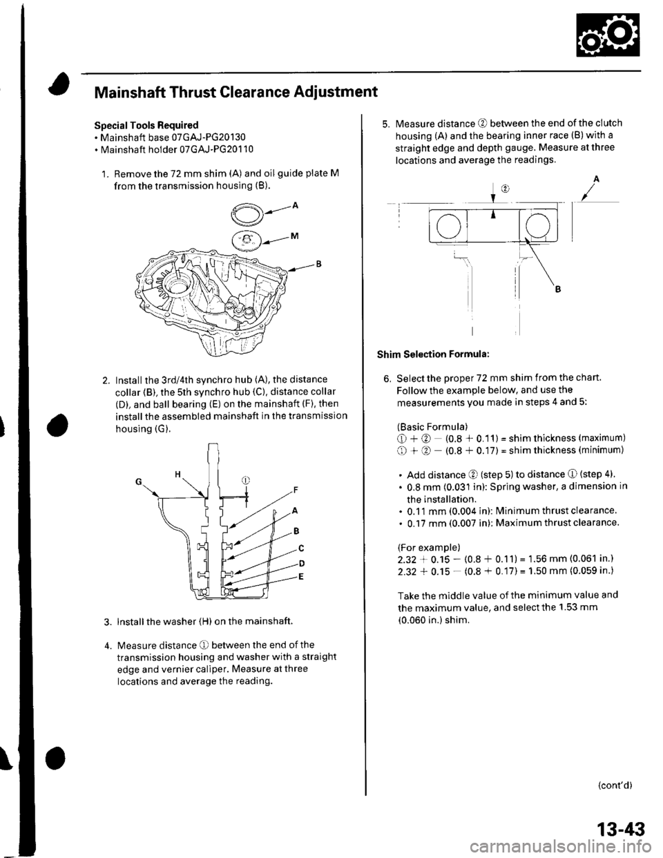
Mainshaft Thrust Clearance Adiustment
Special Tools Required. Mainshaft base 07GAJ-PG20130. Mainshaft holder 07GAJ-PG20110
1. Remove the 72 mm shim (A) and oilguide plate M
from the transmission housing (B).
,5---ov/
Installthe 3rd/4th synchro hub (A), the distance
collar (B), the 5th synchro hub {C). distance collar
(D), and ball bearing (E) on the mainshaft (F), then
installthe assembled mainshaft in the transmission
housing (G).
lnstall the washer (H) on the mainshaft.
Measure distance O between the end of the
transmission housing and washer with a straight
edge and vernier caliper. Measure at three
locations and average the reading.
5.Measure distance @ between the end of the clutch
housing (A) and the bearing inner race (B)with a
straight edge and depth gauge. Measure at three
locations and average the readings.
A
Shim Selection Formula:
6, Select the proper 72 mm shim from the chan.
Follow the example below, and use the
measurements you made in steps 4 and 5:
(Basic Formula)
O+@ (0.8 * 0.11) = shim thickness (maximum)
O + O (0.8 + 0.17) = shim thickness (minimum)
. Add distance O (step 5) to distance O (step 4)
. 0.8 mm (0.031 in): Spring washer, a dimension in
the installation.. 0.11 mm (0.004 in): lvlinimum thrust clearance
. 0.17 mm (0.007 in): Maximum thrust clearance.
(For example)
2.32 + 0.15 - (0.8 + 0.11)= 1.56 mm (0.061 in.)
2.32 + 0.15 - (0.8 + 0.17)= 1.50 mm (0.059 in.)
Take the middle value of the minimum value and
the maximum value, and select the 1.53 mm
(0.060 in.) shim.
{cont'd)
13-/li|
Page 463 of 1139
\
Backlash lnspection
1.Place the differential assembly on V-blocks (A), and
install both axles.
Measure the backlash of both pinion gears (B) with
a dial indicator (C). lf the backlash is not within the
standard, replace the differential carrier.
Standard (New): 0.05 0.15 mm (0.002 0.006 in.)
Final Driven Gear/Carrier
Replacement
1. Remove the bolts (left-hand threads) in a crisscross
pattern in several steps, then remove the final
driven gear (A)from the differential carrier {B).
t x t.o mm {to)121 Nm(12.3 kgf m,89 rbt.ft)
Install the final driven gear with the chamfer on the
inside diameter facing the carrier. Align the marks
on the final driven gear and the carrier. Tighten the
bolts in a crisscross pattern in several steps.
13-53
Page 466 of 1139
M/T Differential
Differential Thrust Clearance Adjustment
SpecialTool Required
Driver. 40 mm LD. 07746-0030100
1. Install an 80 mm shim that's the same size as the
one you removeo.
2.Install the differential assembly into the clutch
housing.
13-56
5.
Install the transmission housing onto the clutch
housing, then tighten the 8 mm flange bolts in a
crisscross pattern in several steps (see step 15 on
page 13-48).
8 x 1.25 mm
27 N m (2.8 kgf'm, 20 lbf.ft)
Use the special toolto bottom the differential
assembly in the clutch housing.
00746-0030100
Measure the clearance between the 80 mm shim
and bearing outer race in the transmission housing.
Standard: 0 0.10 mm l0 0.004 in.)
-i.w.t ..1-- -- :,- -=.
Page 481 of 1139
Driveline/Axle
Driveshafts Reassembly (cont'dl
18. Unwind the boot band tool, and cut off the excessfree end of the bandto leave a 5- 10 mm (0.2-0.4
in.) tail protruding from the clip
19. Bend the band end (A) by tapping it down with anammer.
NOTE;. Make sure the band and clip do not interfere withanything and the band does not move.. Remove any grease remaining on the
surrounding surfaces
20. Repeat steps 12 through 19 for the band on theother end of the boot.
16-14
{
2'1. Installthe new set ring.