2002 HONDA CIVIC oil
[x] Cancel search: oilPage 885 of 1139

Gauges
\-Component Location Index
PARKING BRAKE SWITCHpage 19-10
FUEL GAUGE SENDINGpage 11-156ENGINE OIL PRESSURE SWITCHpage 8-4
GAUGE ASSEMBLYSelJ-diaqnostic Procedure, page 22-56Gauqe dulb Replacement, page 22 63Rep6cement, page 22-64Coolant Temperature GaugeTroLrbleshooting, page 22'64
BRAKE FLUID LEVEL SWITCHpage 19-10VEHICLE SPEED SENSOR {VSS)Troubleshooting, page 22-65Beplacement, page 22-67
22-54
\
Page 887 of 1139

Gauges
Self-diagnostic Procedure
The gauge assembly has a self-diagnosis function.. The Beeper Drive Circuit Check. The Indicator Drive Circuit ChecL. The LCD Segments Check. The Gauges Drive Circuit Check (Speedometer, Tachometer, Fuel gauge, Coolant temperature gauge). The Communication Line Check (the coolanttemperature signal line between the gauge and ECM)
NOTE: Indicators are also controlled via the communication line.
Entering the self-diagnosis f unction:
Before doing the self-diagnosis function, check the No. 9 (10A) fuse in the under-hood fuse/relay box and No. 10 {7.5A)fuse in the under'dash fuse/relay box.
1. Push and hold the trip/reset button.
2. Turn the lighting switch ON.
3. Turn the ignition switch ON (ll).
4. Within 5 sec., turn the lighting switch OFF, then ON and OFF again.5. Within 5 sec., release the trip/reset button, then push and release the button four times reDeatedlv.
NOTE:. While in the self-diagnosis mode, the dash lights brightness controller operates normally.'Whileintheself-diagnosismode,thetrip/resetbuttonisusedtostartthebeeperdrivecircuitcheckandthegauge
drive cicuit check.. lf the vehicle speed exceeds 1.2 mph 12 km/h) orthe ignition switch is tu rned OFF, the self,diag nosis mode ends.
oN flrl
lgnition
Switch
Lighting
Switch
Trip/Reset
Switch-> Move to selt-diagnosis mode.
5 sec.5 sec.
The Beeper Drive Circuit Check:
When entering the self-diagnosis mode, the beeper sounds five times
The Indicator Drive Circuit Check:
When entering the self-diagnosis mode, the following indicators blink.
Seat belt indicator, Door/hatch indicator, Brake system, Lowfuel indicator, Maintenance required indicator (USA),
Washer fluid level indicator (Canada), Oil pressure light.
v
OFF
22-56
Page 937 of 1139

Rear Window Defogger
Function Test
NOTE:. Be careful not to scratch or damage the defogger
wires with the tester probe.
. Before testing, check the No. 11 (30A) fuse in the
under-hood fuse/relay box and No. '14 ('10A) fuse in
the under-dash fuse/relay box.
1. Check for voltage between the ve rtica I dividersand
body ground with the ignition switch and defogger
switch ON.
There should be voltage as shown.
. lf there is no voltage. checkfor:- faulty defogger relay.- an open in the BLK, BLK,/YEL, or YEL/BLK wire.- taulty heater control panel.
. lf there is battery voltage, goto step 2.
6V
Check for continuity between the negative terminal(B) and body ground.
lf there is no continuity, check for:. an open in the BLK wire.. Poor body ground at the window antenna coil
mounting bolt.
Touch the voltmeter positive probe to the halfway
point of each defogger wire. and the negative
probe to the negative terminal,
There should be about 6 V with the ignition switch
and the defogger switch ON.
. lf thevoltage is asspecified, the defoggerwlre is
oK.. lf the voltage is not as specified, repair the
defogger wire.- lf it is more than 6 V, there is a break in the
negative half of the wire.- lf it is less than 6 V, there is a break in the
positive half of the wire.
2.
22-106
2.
Defogger Wire Repair
NOTE: To make an effective repair, the broken section
must be no longer than one inch.
1. Lightly rub the area around the broken section (A)
with fine steel wool, then clean it with alcohol.
Carefully mask above and below the broken portion
of the defogger wire (B) with transparent tape {C).
Mix the silver conductive paint thoroughly. Using a
small brush, apply a heavy coat of paint extending
about 1/8 inch on both sides of the break. Allow 30
minutes to dry.
Check for continuity in the repaired wire.
Apply a second coat of paint in the same way. Let it
dry 3 hours before removing the tape.
5.
Page 940 of 1139

Circuit Diagram
- No.20lOAl :USNo.20150 ) :Canda
A Clos.d fom lh€ ruto nop poshio. to lh€ doed porhionB Clo!.d in th€ lilt or do3.d poilionC : Clo!.d in any op.n (io! riltl posirionD Clos.d in th€ tilt po6iiion
UNDIR OAS8 FUSE/NILAY MX
BL|(
+
G50t
8LI
I
G5{1
22-109
Page 967 of 1139
![HONDA CIVIC 2002 7.G Workshop Manual Wipers/Washers
Circuit Diagram - Windshield
UNOEN HOOD FL]SE/8ELAY BOX IGNITIONSWITCN7{ F;^--il I 6\
U-I^-- -:-;--u,Hr-
o,f-*""
\1
L\
MULTIPIIXcoiln0LUNIT
22-136
\,! HONDA CIVIC 2002 7.G Workshop Manual Wipers/Washers
Circuit Diagram - Windshield
UNOEN HOOD FL]SE/8ELAY BOX IGNITIONSWITCN7{ F;^--il I 6\
U-I^-- -:-;--u,Hr-
o,f-*""
\1
L\
MULTIPIIXcoiln0LUNIT
22-136
\,!](/manual-img/13/5744/w960_5744-966.png)
Wipers/Washers
Circuit Diagram - Windshield
UNOEN HOOD FL]SE/8ELAY BOX IGNITIONSWITCN'7{ F;^--il I 6\
U-I^-- -':-;--u,Hr-
o,f-''*""
\1
L\'
MULTIPIIXcoiln0LUNIT
22-136
\,!
Page 1022 of 1139

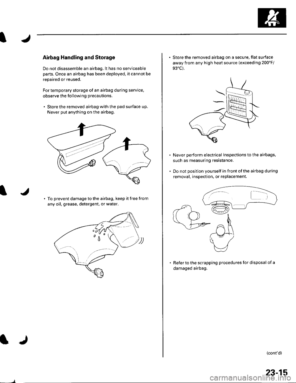
Airbag Handling and Storage
Do not disassemble an airbag, lt has no serviceable
parts. Once an airbag has been deployed, it cannot be
repaired or reused.
For temporary storage of an airbag during service,
observe the following precautions.
. Store the removed airbag with the pad surface up.
Never put anything on the airbag.
To prevent damage to the airbag, keep it free from
any oil, grease, detergent, or water,
23-15
. Store the removed airbag on a secure, flat surface
away from any high heat source (exceeding 200'Fi
Never perform electrical inspections to the airbags,
such as measuring resistance.
Do not position yourself in front of the airbag during
removal, inspection, or replacement.
Refer to the scrapping procedures for disposal of a
damaged airbag.
(cont'd)
Page 1023 of 1139

sRs
Precautions and Procedures {cont'dl
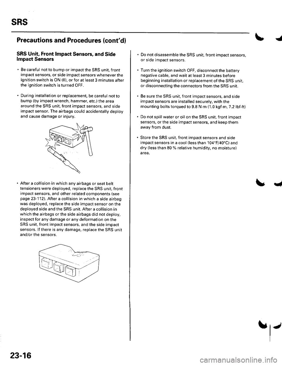
SRS Unit, Front lmpact Sensors, and Side
lmpact Sensors
. Be careful not to bump or impact the SRS unit, front
impact sensors, or side impact sensors whenever the
ignition switch is ON (ll), or for at least 3 minules after
the ignition switch is turned OFF.
. During installation orreplacement, be careful notto
bump (by impact wrench, hammer, etc.) the area
around the SRS unit, front impact sensors, and sjde
impact sensor. The airbags could accidentally deploy
and cause damage or injury.
After a collision in which any airbags or seat belt
tensioners were deployed. replace the SRS unit, front
impact sensors, and other related components (see
page 23-112). After a collision in which a side airbag
was deployed. replace the side impact sensor on the
deployed side and the SRS unit. After a collision in
which the airbags or the side airbags did not deploy,
inspect for any damage or any deformation on the
SRS unit, front impact sensors, and the side impact
sensors. lf there is any damage, replace the SRS unit
and/or the sensors.
23-16
.j
. Do not disassemble the SRS unit, front impact sensors,
or side impact sensors.
. Turn the ignition switch OFF, disconnect the battery
negative cable, and wait at least 3 minules before
beginning installation or replacement of the SBS unit,
or disconnecting the connectors from the SRS unit.
. Be sure the SRS unit, front impact sensors, and side
impact sensors are installed securely. with the
mounting bolts torqued to 9.8 N.m (1.0 kgf.m,7.2 lbf.ft)
. Do not spill wateroroil on the SRS unit, front impact
sensors, or the side impact sensors, and keep them
away from dust.
. Store the SRS unit, front imDact sensors and side
impact sensors in a cool (less than 104"F/40'C) and
dry (less than 80 % relative humidity, no moisture)
area.
I
Page 1134 of 1139

Service Manual Index
(cont'dl
Brake System Indicator CircuitCircuit DiagramConventional Brake Components..... 19-9TroubleshootingABS/TCS Components .... ....... ...... 19-55
Bulb, GeugeRep|acemenl................ .. ............2263
Bulb, HeadlightReplacement ......................................... 22-A1
Bumper, FrontRemoval/1nsra11ation ............................ 20 85
Bumper, RearRemoval/lnstallation... ... . .....20.86
Combination Light SwilchTesVReplacement ..............................22 80
Connecting Rod BearingsRep|acement...................... .......-....7-8
Connecting Rod Boltsf nspection ....................-.-.-.-.................... 7 -24
Connecting RodsInspection ........,,.,.,...,.,.,.,.,,,,.,,,.,.,.,.,.,.,.,.. 7 5
Connectors(See first page of this Index)
Conventional Brake Component3Component Location Index ................... 19'3Troub1eshootin9 ..................................... 19-4
Cylinder Head AssemblyComponent Location Index ..................... 6-3Inspection ................................................. 6 6Removal ..........&�23Insta11alion .............................................. 6 39
Cylinder Head Cover8emova1 ..............-.-................................. 6-22Installation ..............................................6-41
Cylinder Head, BareInspecton..,.....,.
D
c
Cable ReelReplacement....................................... 23-1 19
CamshaftInspection .......................-...-................... 6-29
Cargo Area LightTesVRep1acement ................................ 22-97
CarpetReplacement.....-...-..... ... ......-.20-55
Ceiling Light-estrReplacement ................................ 22.96
Charging SystemComponent Location Index................... 4-20Circuit Diagram ...................................... 4-21
19-8
CoolantInspection .................. ..... .. 106Replacement................. ... . .. 10 6
Coolant Temperature Gat|geTroub1eshootin9................................... 22 64
Cooling SyslemComponent Location Index................... 10-2
Countershaft BearingsReplacement............... ..................... 13-42
Cowl CoverReplacement............... .. ..... ....20-95
CrankshaftRemoval .................................................. 7 -12
Repair ..................
Inspec(on,,,,,........1 14
Dampers. FrontReplacement................ ..................... 18 20
Oampers, RearRep1acement......................................... 18-34
Dash VentsBemoval/lnstallation .-.......................... 20-64
DashboardBemoval/1nsta11ation ............................ 20-66
Oashboard Center PanelRemoval/1nstaf 1ation ............................ 20 62
Dashboard Lower CoverRemoval/lnstallation ...................... 20-59, 63
Dashboard Under CoverRemoval/lnstallation ............................ 20 60
Diff erential Carrier Bearings, M/TRep1acement,,......,...,...,.,.,,,.,.,,,........,.,. 13-54
Ditferential Oil Seals, M/T8ep1acement......................................... 13-55
Differential Pinion Gears, M/TInspection .,....-,.,,,.,..,.-,.,.........,.,.,,, 13 53
OLC CircuitTroubleshooting ................................ 1 1-109
Door GlassRep1acement.,.,,,,,,,,,,,.,,,,,,,,,,.,.,.,.,.,,,,,,.,, 20-9Adjustment. .. .....................20-11
Door Glass WeathelstripsReplacement .............-.. . . . ..........-......20 10
Door LatchesReplacement ..........-.-.............................. 20-7
Door Lock ActuatorsTest ...................................................... 22-154
Door Lock Knob SwitchesTest -......... . . . - . . . . . . . . ......22-160
Door Lock SwitchesTest ........... ............................ ............. 22-160
Door Outer HandlesRep1acemen1 ........................................... 20-6
3
Child Seat Tether AnchorRemoval/lnstaf lat;on .. ........................ 23 11
CKP (Crankshaft Position) SonsorReplacement....................................... 1 1-116
ClutchComponentLocation 1ndex................... 12-3Rep1acemen1........................................... 12-9
Clutch InteYlock SwitchTest.....-........-...-............. ...---.-.......4-6
Clutch Master CylinderReplacement........................................... 12 5
clutch PedalAdjustment ............................................. 12 4
Clutch Pedal Position SwitchTest.,.,,,,,.,,,.,.,,,,,,.,.,,,,,,,,,.,,,,,.. ......445
lnstallation.................. . ..... .....1-24
Crankshalt Main BearingsReplacement........-.-.................................. 7-6
CrankshaftOil Seal,Transmission End1nstanation .............................................. 7 28
Crankshafl PulleyRemoval/lnstallation -..................-.......... 6-1 1
Cruise Control Actuator
Troubleshooting
Clutch Slave CylindorBeplacemeit...
...................... 4-43
.......4-22
Test
12-1
RepIacement........................................... 4-44
Cruise Control Actuator CableAdjustment ............................................. 4 45
Cruise Control Main SwitchTesVRep1acement .................................. 4 42
Cruise Control Set/Resume/Cancel SwitchTesVRep1acement .................................. 4 42
Cruise Control SystomComponent Localion Inde\................... 4-36Circuit Diagram ....-................................. 4 37
Cruise Control UnitInputTest.............................. .. ...4,40CMP {Camshaft Positionl Senso]Replacement....-...-.............................. 1 1-128
CMP (TDC) SensorsReplacement............-.......................... 1 1 1 14