2002 HONDA CIVIC check engine
[x] Cancel search: check enginePage 834 of 1139

General Troubleshooting Information
Tips and Precautions
Bef ore Troubleshooting
1. Check applicable fuses in the appropriate fuse/relay
oox.
2. Check the battery for damage. state of charge, and
clean and tight connections.
. Do not quick-charge a battery unless the battery
ground cable has been disconnected, otherwise
you will damage the alternator diodes.. Do not attempt to crank the engine with the
battery ground cable loosely connected or you
will severely damage the wiring.
Handling Connectors. Make sure the connectors are clean and have no
loose wire terminals.. Make sure multiple cavity connectors are packed with
dielectric grease (except waterti ght connectors).. All connectors have push-down release type locks (A).
Some connectors have a clip on their side used to
attach them to a mount bracket on the body or on
another component. This clip has a pull type lock.
Some mounted connectors cannot be disconnected
unless you first release the lock and remove the
connector from its mount bracket (A).
Never try to disconnect connectors by pulling on their
wires; pull on the connector halves instead.
Alwavs reinstall Dlastic covers,
Before connecting connectors, make sure the
terminals (A) are in place and not bent.
(cont'd)
22-3
Page 876 of 1139

Under-dash Fuse/Relay Box
SocketRefTerminal Connects to
B
c
D
E
F
G
H
J
K
M
N
o
P
Power window relay
o
R
S
Starter cut relay
T
Taillight relay
Turn signal/hazard relay
U
W (Memory erase signal (MES)
connector)
X
Y
2
3
1
5
19
9
I
20
24
22
27
26
7
6
10
25
14
18
11
l5
to
17
28
5
6
14
13
12
10
3
:
11'10
1:
.o^
;;
4
8
2
i
nl
al
lt
2
Dashboard wire harness B {see page 22-30)
Dashboard wire harness B {see page 22-30)
Dashboard wire harness B (see page 22-30)
ECM wire harness (see page 22-32)
ECI\4 wire harness (see page 22-32)
Engine compartment wire harness (see page 22-'l8l
Engine compartment wire harness (se e page 22-181
Engine compartment wire harness (see page 22-18)
Engine compartment wire harness (se e page 22-18)
Engine compartment wire harness (see page 22-18)
Dashboard wire harness A (see page 22-26)
Dashboard wire harness A (see page 22-26)
Dashboard wire harness A (see page 22-26)
Dashboard wire harness A (see page 22-26)
Dashboard wire harness A (see page 22-26)
Floor wire harness (see page 22-34)
Floor wire harness (see page 22-34)
ECM wire harness (see page 22-32)
Dashboard wire harness B (see page 22-30)
Multiplex control unit service check connector
Optional connector
Optional connector
Floor wire harness (see page 22-34)
{Plugs directly into the multiplex control(Pluqs directlv into the multiDlex control
unat)
unrl)
I
13
tn--rlI U LI L.] L.Jh--n-UL]L]UL]
I] L] L] LI L]
!3 12
22-45
Page 895 of 1139

Gauges
2.
3.
Gauge Assembly Replacement
1.Remove the instrument panel (see page 20-59),
then remove the upper column cover {see page 17-
Place a clean shop towel (A) under the gauge
assembly to prevent scratching the steering
colum n or dash panel.
Remove the screws from the gauge assembly (B).
Disconnect the connectors (C), and remove thegauge assemDry.
Installthe gauge assembly in the reverse order of
removal.
Coolant Temperature Gauge
Troubleshooting
Before testing, check the No. I { 10A) fuse in the under-
hood fuse/relay box and the No. '10 (7.5A) fuse in the
under dash fuse/relay box.
1. Start the engine, and check the malfunction
indicator lamp (MlL).
Does the MIL come on?
YES- Troubleshoot the cause of the ECM DTC (see
page 1 1-57), and recheck.
NO-Go to step 2.
2. Check for a multiplex control unit DTC (see page
22,168).
ls a DTC ind icated?
YES Troubleshooting the cause of the multiplex
control unit DTC {see page 22-168), and recheck.
NO Go to step 3.
3. Do the communication line check with the self-
diagnosis procedure (see page 22-56).
ls the word "Error" indicated on the odo/ttip
d isplay ?
YES The gauge cannot receive the signal from the
multiplex control unit and the ECI\,4. Check for an
open in the WHT/GRN wire (gauge connector
terminal B 13). lf no open is found, go to step 5.
NO Go to step 4.
4. Do the gauge drive circuit check with the self-
diagnosis procedure (see page 22-56).
Does the temperature gauge needle sweep lrom
the minimum position to the maximum, then tetutn
to the minimum position?
YES Go to step 5.
NO Replace the gauge assembly.l
5. Substitute a known-good ECM and recheck.
Did the symptom/ ind ication go away?
YES Replace the ECM.
NO Substitute a known good gauge assembly. lf
the symptom/indication goes away, replace thegauge assembly.l
4.
22-64
Page 896 of 1139

IVehicle Speed Signal Circuit Troubleshooting
Special Tools Required:
Test Harness 07LAJ-PT3020A
Before testing, inspect the No. 4 (10A) and No. 10 (7.5A)
fuses in the under-dash fuse/relay box.
1. Disconnect the 3P connector from the vehicle
speed sensor (VSS) {A).
Connect the test harness only to the engine wire
harness.
Connect the RED test harness clip (B) to the positive
probe of an ohmmeter. Cover the white (C) and
green {D) test harness leads with protective tape (E).
Check for continuity between the RED test harness
clip and body ground,
ls there continuity?
YES Go to step 5.
NO Repair open in the BLK wire between the VSS
and G 101.I
3.
4.
5. Connect the WHT test harness cliD (B) to the
positive probe of a voltmeter, and connect the RED
test harness clip (C) to the negative probe.
Turn the ignition switch ON (ll).
le thara h2ltarv v^ltada?
YES-Go to step 7.
NO Repair open in the BLK,/YEL wire between the
VSS and the under-dash fuse/relay box.l
Disconnect the WHT test harness clip (B).
Connect the GRN test harness clip {D) to the
positive probe of a voltmeter.
Is there 5 V or more?
YES- Go to step 9.
NO Repair short or open in the BLUMHT or WHT/
GRN wire between the VSS and the cruise control
unit, or the ECM.I
(cont'd)
7.
8.
22-65
Page 996 of 1139

)
I
Troubleshooting
Before troubleshooting the immobilizer system,
troubleshoot any EClvl Diagnostic Trouble Codes (DTCS)
(see page 11-3), and make sure the ECM has no
malfunction.
Note these items before trou bleshooting:
. Due to the action of the immobilizer system, the
engine takes slightly more time to start than on a
vehicle without an immobilizer system.. When the system is normal, and the proper key is
inserted, the indicator light comes on for 2 seconds,
then it will go off.. If the indicatorstartsto blink after 2 seconds, or if the
engine does not start. remove any other immobilizer
keys or large key fobs on the key ring, then repeat the
starting procedure.
lf the engine still does not start, continue with thisprocedure.
1. Turn the ignition switch ON {ll) with proper key.
2. Check to see if the immobilizer indicator light
comes on.
Does the indicator light blink?
YES Disconnect the 7P connector from the
immobilizer control unit-receiver, then go to step 9.
NO Check for these problems, then go to step 3.
. Blown No. 9 (10A)fuse in the under-hood
fuse/relay box.I. An open in the wire between the gauge assembly
and the immobilizer control unit-receiver.l. A faulty immobilizer indicator light,I. An open in the wire between the gauge assembly
and the under-hood fuse/relay box.l
Remove the driver's dashboard lower cover (see
page 20-59).
Remove the steering column lower cover (see page
11-9).
l
-_--t
22-165
5. Disconnect the 7P connector (A)from the
immobilizer control unit-receiver (B),
Check for voltage between the immobilizer control
unit-receiver 7P connector No. 7 terminal and body
ground.
ls there battery voltage?
YES-Go to step 7.
NO Check for these problems;
. Blown No. 9 {10A)fuse in the under-hood fuse/
relay box.l. An open in the WHT/RED wire.l
Check for voltage between the immobilizer control
unit-receiver 7P connector No. 6 terminal and bodyground with the ignition switch ON {ll).
ls there battery voltage?
YES- Go to step 8.
NO Check for these problems:
. Blown No.6 (15A)fuse in the under-hood
fuse/relay box,I. Faulty PGM-Fl main relay 1,t. An open in the YEUBLK wire.l
1.
(cont'd)
Page 1021 of 1139

sRs
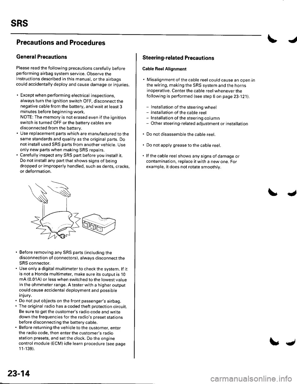
Precautions and Procedures
General Precautions
Please read the following precautions carefully beforeperforming airbag system service. Observe theinstructions described in this manual. or the airbags
could accidentally deploy and cause damage or injuries.
. Except when performing electrical inspections.
always turn the ignition switch OFF, disconnect the
negative cable from the battery, and wait at least 3minutes before beginning work.
NOTE: The memory is not erased even if the ignition
switch is turned OFF or the battery cables are
disconnected from the battery.. Use replacement pans which are manufactured to the
same standards and quality as the original parts. Do
not install used SRS parts from another vehicle. Useonly new pans when making SRS repairs.. Carefully inspect any SRS part before you install it.
Do not install any part that shows signs of being
dropped or improperly handled, such as dents, cracks,
or deformation.
. Before removing any SRS parts (including the
disconnection of connectors), always disconnect the
SRS connector.. Use only a digital multimeter to check the system. lf itis not a Honda multimeter, make sure its outout is 10mA (0.01A) or less when switched to the lowest value
in the ohmmeter range. A tester with a higher output
could cause accidental deployment and possible
injury.. Do not put objects on the front passenger's airbag.. The original radio has a coded theft protection circuit.
Be sure to get the customer's radio code and write
down the frequencies for the radio's preset stations
before disconnecting the battery cable.. Before returning the vehicle to the customer, enter
the radio code. then enter the customer's radio
station presets, and set the clock. Do the engine
control module (ECM) idle learn procedure (see page
11-139).
23-14
c
Steering-related Plecautions
Cable Reel Alignment
. Misalignment of the cable reel could cause an open in
the wiring, making the SRS system and the horns
inoperative. Center the cable reel whenever the
following is performed (see step 6 on page 23-121).
- Installation of the steering wheel- Installation of the cable reel- Installation ofthe steering column- Other steering-related adjustment or installation
. Do not disassemble the cable reel.
. Do not apply grease to the cable reel.
. lf the cable reel shows any signs of damage or
contamination. replace it with a new one. For
example, it does not rotate smoothly.
Page 1033 of 1139

sRs
General Troubleshooting Information (cont'dl
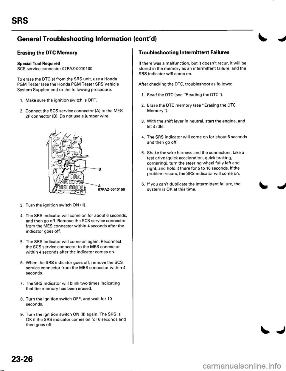
Erasing the DTG Memory
Specisl Tool Required
SCS service connector 07PAz-0010100
To erase the DTC(S)from the SRS unit, use a Honda
PGM Tester {see lhe Honda PGfM Tester SRS Vehicle
System Supplement) or the following procedure.
1. Make sure the ignition switch is OFF.
2. Connect the SCS service connector {A) to the MES
2P connector (B). Do not use a jumper wire.
07PAZ-0010100
3. Turn the ignition switch ON (ll).
4. The SRS indicator will come on for about 6 seconds,
and then go off. Remove the SCS service connector
from the MES connector within 4 seconds after the
indicator goes off.
5. The SRS indicator will come on again. Reconnect
the SCS service connector to the MES connector
within 4 seconds after the indicator comes on.
6. When the SRS indicator goes off, remove the SCS
service connector from the MES connector within 4
seconds.
7. The SRS indicator will bllnk two times indicating
that the memory has been erased.
8. Turn the ignition switch OFF, and wait for '10
seconds.
9. Turn the ignition switch ON (ll) again. The SRS js
OK if the SRS indicator comes on for 6 seconds and
then goes off.
23-26
\J
Troubleshooting lntermittent Failures
lf there was a malfunction, but it doesn't recur. it will be
stored in the memory as an intermittent failure, and the
SRS indicator will come on.
After checking the DTC, troubleshoot as follows:
1. Read the DTC (see "Reading the DTC").
2. Erase the DTC memory (see "Erasing the DTC
Memory").
3. With the shift lever in neutral, start the engine, and
let it idle.
The SRS indicator will come on for about 6 seconds
and then go off.
Shake the wire harness and the connectors. take a
test drive (quick acceleration, quick braking,
cornering), turn the steering wheel fully left and
right, and hold it there for 5 to '10 seconds. lf the
problem recurs, the SRS indicator will come on.
lf you can't duplicate the intermittent failure, the
system is OK at this time.
4.
Page 1084 of 1139

DTC 9-6: Faulty Left Front lmpact Sensor
Special Tools Required. SRS inflator simulator 07SAZ-TB4011A. SRS simulator lead H 07YM-S3AA100
1. Erase the DTC memory (see page 23-26).
2. Turn the ignition switch ON (ll), and check that the
SRS indicator comes on for about 6 seconds and
then goes off.
Does the SRS indicator stay on?
YES-Go to step 3.
NO Intermiftent failure, system is OK at this time.
Go to Troubleshooting Intermittent Failures (see
page 23-26).
3. Turn the ignition switch OFF. Check the
connections between SRS unit connector A (18P)
and the SRS unit. between the engine
compartment wire harness 2P connector and the
left front impact sensor {see page 23-13), and at
connector C401.
Are the connections OK?
YES Go to step 4.
NO-Repair the poor connections and retest. lf DTC
9-6 is still present, go to step 4.
Turn the ignition switch OFF. Disconnect the
battery negative cable. and wait for 3 minutes.
Disconnect the driver's airbag 4P connector from
the cable reel (see step 2 on page 23-21).
Disconnect the front passenger's airbag 4P
connector from dashboard wire harness B {see step
3 on page 23-21).
Disconnect both seat belt tensioner 2P connectors
from the floor wire harness (see step 5 on page 23-
22).
7.
9.
10.
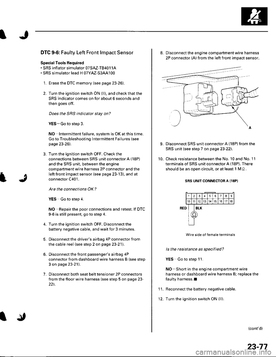
8. Disconnect the engine compartment wire harness
2P connector {A) from the left front impact sensor.
Disconnect SRS unit connector A {18P) from the
SRS unit (see step 7 on page 23-22J.
Check resistance between the No. 10 and No. 11
terminals of SRS unit connector A (18P). There
should be an oDen circuit. or at least 1 M 0 .
SRS UNIT CONNECTOR A (18PI
Wire side of female terminals
ls the resistance as specitied?
YES Go to step 1 1.
NO-Short in the engine companment wire
harness or dashboard wire harness B; replace the
faulty harness.I
Reconnect the battery negative cable.
Turn the ignition switch ON { ll).
{cont'd}
RED
11.
12.
2356789
10tl1Zt315161718
I
T
ILK
23-77