Page 107 of 1139

Cylinder Head
Crankshaft Pulley Removal and
Installation (cont'dl
Installation
1. Clean the crankshaft pulley (A), crankshaft (B), bolt(C). and washer (D). Lubricate as shown below.
. .: Clean
O; Lubricate
Installthe crankshaft pulley, and hold the pulley
with holder handle (A) and holder attachment {B).
B07NAB-0010iroA
A07JAB-001020A
Tighten the bolt to 245 N.m (25.0 kgf.m, 181 tbf.ft)with a torque wrench and 19 mm socket (C). Do notuse an impact wrench.
Install the splash shield (see step 20 on page 5-12).
Insta ll front tires/wh eels.
ll
ll
t[] rL-'....-----=a
(-, ,
5U-1JItt-
5.
6-12
\-
Cam Chain Removal
NOTE: Keep the cam chain away from magnetic fields.
1. Turn the crankshaft pulley so ils top dead center(TDC) mark (A) lines up with the poinrer (B).
Remove the front tires/wheels.
Remove the splash shield.
a
2.
3.
-,,--.=.-----__--_
4. Remove the drive belt (see page 4-26).
5. Remove the cylinder head cover (see page 6-22).
6. Remove the crankshaft pulley (see page 6-11).
\
Page 496 of 1139

Steering
Steering Wheel Rotational Play
Check
1. Turn the front wheels to the straight ahead position.
2. Measure how far you can turn the steering wheel
left and right without moving the front wheels.
. lf the play is within the limit, the gearbox and
linkage are OK.. lf the playexceedsthe limit, adjustthe rack guide
{see page '17-13). lf the play is still excessive after
rack guide adjustment, inspect the steering
linkage and gearbox {see page 17-5).
BOTATIONAL PLAY: 0 10 mm (0-0.39 in.l
+:
17-4
Power Assist Check
Start the engine, and let it idle.
Attach a commercially available spring scale to the
steering wheel. With the engine idling and the
vehicle on a clean, dry floor, pull the scale as
shown, and read it as soon as the tires begin to turn.
\
1.
3. lf the scale reads no morethan 29 N (3.0 kgf,6.6 lbf),
the power assist is OK. lf it reads more, check these
items:
. Front tire pressure. Steering linkage (see page 17-5). Rack gulde adjustment (see page 17-13). EPS system (see page 17-18)
Page 562 of 1139

Front and Rear Suspension
WheelAlignment
The suspension can be adjusted for front camber, front
toe, and rear toe. However, each of these adjustments
are interrelated to each other. For example, when you
adjust the toe, the camber changes. Therefore, you
must adjust the front wheel alignment whenever you
adjust the camber or toe.
Pre-Alignment Checks
For proper inspection and adjustment of the wheel
alignment, do these checks:
1. Release the parking brake to avoid an incorrect
measurement.
Make sure the suspension is not modified.
Check the tire size and tire pressure
Tire size:
Front/rear: 195/60R15
Tire pressure:
Front: 230 kPa {2.3 kgf/cm',33 psil
Rear: 210 kPa |'2.1 kgf/cm', 30 psi)
Check the runout of the wheels and tires.
Check the suspension ball joints. (Hold a wheel
with your hands, and move it up and down and
right and left to check for wobbling),
2.
3.
Bounce the vehicle up and down several times to
stabilize the suspension.
18-4
Front Caster lnspection
Use commerciallv available comDuterized four wheel
alignment equipment to measure wheel alignment
(caster, camber, toe, and turning angle). Follow the
eouioment manufacturer's instructions.
Check the caster angle. lf the caster angle is not within
the specification, check for bent or damaged
susoensron comoonents.
Front caster angle: 1'40't 1"
\
Page 632 of 1139
ABS Gomponents
System Description (cont'd)
Features
When the brake pedal is pressed during driving, the wheels can lock before the vehicle comes to a stop. In such an
event. the maneuverability of the vehicle is reduced if the front wheels are locked, and the stability of the vehicle is
reduced if the rear wheels are locked, creating an extremely unstable condition. The ABS precisely controls the slip
rate of the wheels to ensure maximum grip force from the tires, thereby ensuring the maneuverability and stability of
the vehicle.
The ABS calculates the slip rate of the wheels based on the vehicle speed and the wheel speed, then it controls the
brake fluid pressure to reach the target slip rate.
Grip Force of Tire and Road Surface
TARGET SLIP RATE
COEFFICIENT OFFRICTION
SLIP RATE
19-38
Page 1139 of 1139

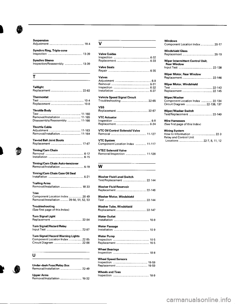
SuspensionAdjustment................-............................184 VComponent Location Index................. 20-17
Windshield GlessReplacement............-..............-............. 20 19
Synchro Ring, Triple-coneInspection...............-..........................1339 ValveGuides
Synchro SleeveInspectaon/Reassemb1y ....................... 13 39
Inspection ............-.-................................ 6 32Beplacement ..........-................................ 6 33 Wiper Intermittent Control Unit,Rear WindowInput Test
T
Valve SeatsRepair ...................................................... 6 35.....22-134
WiDer Motor, Rear WindowRep1acement....................................... 22-1 46Adjustment .-.-.......Removal ...-...-......................................-... 6-31 WiDer Motor, windshield6-9
.....6-32 Test.......-..........-.....-.............................22-143Taillight
ThermostaiTest ........................
Inspec!on
Vehicle Speed Signal Circuit
VTC System
Wiper/WasheI
Wi.ing System
10 4 Troubleshooting .....-... ..........................22-65 Component Location In dex ..............22-134Replacement.....-...-....... ...................... 10 IvssThrottle BodyTest ..................Removal/lnstallation .. . . . . . .. ... 11-'165 VTC ActuatorDisassembly/Feassemb|y................-11-166 Inspection
Circuit Diagram .......................... 22-136, 131
Replacement -.............. ............ .............22 61 Wiper/Washor SwitchTesVReplacement .............................. 22-1 40
.................68 WireHarnesses
11-160
Replacement ........................................... 6 24 (Seefirstpageofthislndex)Throttle CableAdjustment ...... ...-.................... 11163 VTC Oil ConlrolSolenoid ValveRemoval/1nsta11ation..........................11164 Removal....-...-... |1-127 HowtoIn{ormation ...............................223Belay and Control UnitLocations .-....-.............. -.-.-....- 22-7, 4, 1 1, 12Beplacement.........-............................... 1767 ComponentLocationlndex.............. 11-117Tie-rod Ball Joint Boots
lnstallation
Replacement
Turn Signal/Hazard Relay
tsTiming/Cam ChainVTEC Solenoid Valve...612 Femoval/lnspection....-......................11-128................ 6 15
Timing/Cam Chain Auto-tensionelRemoval/1nsta11ation..............................6-19 W
Troubleshooting{See first page ot this Index)
Turn Signal Light
Timing/Cam Chain CaseOil SealInstallation......................-......................6,21 Washer Fluid Level SwitchTesVReplacement .............................. 22 1 44Trailing ArmsRemoval/lnstallation .............. . . . . ..... 18 33 Washer Fluid ReservoirReplacement ....................................... 22-1 46tnmComponent Location lndex ................- 20 49 Washer Motor, WindshieldRemoval/lnstallation ..-.......20 50,51,52,53 Test -..............-.............. ........................22 144
Washer Tube, WindshieldReplacement......-...-............................ 22 1 47
W.ter Outlet.........22 A4 Installation ..................-........................... '10-9
InputTest........22-87 lnstallation................ 10IWeter Passage
Wheels andTires
Turn Signal/Hazard Warning Lights Water PumpComponent Location In dex .................22 85 Inspection ........................... .. . . . ....... 10 5Circu it Diagram ................-................... 22-86 Replacement .-......................................... 10 5
U
WheelBearingsInspec|ion ....................................... ....... 18 8
Wheel Speed SensorsInspection ..-..,.,.,,.,,,,,.,.,,,...................... 19-59Replac€ment ........-....... . . . . . . .. -.... 19-59UndeFdash Fuse/R€lay BoxRemoval/lnstaf lation ............................ 22-49
Upper ArmsRemoval/|nsta11ation................. ... 18-32
],sInspect|on