2002 HONDA CIVIC reset
[x] Cancel search: resetPage 234 of 1139

lgnition Timing Control
The ECM contains the memory for basic ignition timing
at various engine speeds and manifold absolute
pressure. lt also adjusts the timing according to engine
coolant temperature.
Iniector Timing and Duration
The ECM contains the memory for basic discharge
duration at various engine speeds and manifold
pressures. The basic discharge duration, after being
read out from the memory, is further modified by
signals sent from various sensors to obtain the final
discharge duration.
By monitoring long term fuel trim, the ECM detects long
term malfunctions in the fuel system and sets a
Diagnostic Trouble Code {DTC).
Intake Air Temperature (lAT) Sensor
The IAT sensor is a temperature dependent resistor
{thermistor). The resistance of the thermistor decreases
as the intake air temDerature increases.
Knock Sensor
The knock control system adjusts the ignition timing to
minimize knock.
PIEZOCERAMIC
Malfunction Indicator Lamp lMlLl Indication {ln relation
to Readiness Codes)
The vehicle has certain "readiness codes" that are part
of the on-board diagnostics for the emissions systems.
lf the vehicle's baftery has been disconnected or gone
dead. if the DTCS have been cleared, or if the ECM has
been reset. these codes are set to incomplete. In some
states, part of the emissions testing is to make sure
these codes are set to comDlete. lf all of them are not
set to complete, the vehicle may fail the test and the
test cannot be finished.
To check if the readiness codes are set to complete,
turn the ignition switch ON (ll). but do not start the
engine.TheMILwill comeonforlS 20seconds. lf it
then goes off, the readiness codes are set to complete,
lf it blinks severaltimes, one or more readiness codes
are not set to comolete. To set each code, drive the
vehicle or run the engine as described in the
procedures to set them in this section (see page 1 1-46).
Manifold Absolute Pressure {MAP) Senso]
The MAP sensor converts manifold absolute pressure
into electrical signals to the ECM.
SENSOR UNIT
(cont'd)
11-27
Page 253 of 1139

Fuel and Emissions Systems
How to Set Readiness Codes
Malfunction lndicator Lamp (MlL) Indication
(ln relation to Readiness Codesl
The vehicle has certain "readiness codes" that are part
of the on-board diagnostics for the emissions systems.
lf the vehicle's battery has been disconnected or gone
dead, if the DTCS have been cleared, or if the ECM has
been reset, these codes are set to incomplete. In some
states, part of the emission testing is to make su re these
codes are set to complete. lf all of them are not set to
complete, the vehicle may fail the emission test, or the
test cannot be finished.
To check ifthe readiness codes are complete, turn the
ignition switch ON (ll), but do not start the engine. The
MIL will come on for 15 20 seconds. lf it then goes off,
the readiness codes are complete. lf it blinks several
times, one or more readiness codes are not complete.
To set readlness codes from incomplete to complete.
do the procedure for the appropriate code.
11-46
L
Catalytic Converter Monitor and Readiness
Code
NOTE:. Do not turn the ignition switch off during the
procedure.
. All readiness codes are cleared when the battery is
disconnected or when the ECM is cleared with the
OBD ll scan tool or Honda PG lvl Tester.. Low ambient temperatures or excessive slop-and-go
traffic may increase the drive time needed to switch
the readiness code from incomplete to complete.' The readiness code will not switch to com Dlete until
all the enable criteria are met.. lf a fault in the secondary HO2S system caused the
MIL to come on. the readiness code cannot be set to
comDlete until vou correct the fault.
Enable Criteria. ECT at 158"F (70'C) or higher.. Intake air temperature (lAT) at 20"F (-7'C) or higher.. Vehicle speed is steady, and vehicle speed sensor
(VSS) reads more then 25 mph (13km/h).
Procedure
1. Connect the scan tool to the vehicle's data link \
connector (DLCi, and bring up the tool's generic \"
OBD ll mode.
Start the engine.
Test-drive the vehicle under stop-and-go conditions
with short periods of steady cruise. After about
5 miles (3 km), the readiness code should switch
from incomplete to complete.
lf the readiness code is still set to incomplete, check
for a temporary DTC. lf there is no DTC, one or
more of the enable crlteria were probably not met;
2.
3.
Page 255 of 1139

Fuel and Emissions Systems
a
a
How to Set Readiness Codes (cont'd)
Misfire Monitor and Readiness Code
. This readiness code is always set to available
because misfiring is continuously monitored.. l\4onitoring pauses, and the misfire counter resets, if
the vehicle is driven over a rough road.. Monitoring also pauses, and the misfire counter
holds at its current value. if the throttle position
changes more than a predetermined value, or if
driving conditions fall outside the range of any
related enable criteria,
Fuel System Monitor and Readiness Code
. This readiness code is always setto available
because the fuel system is continuously monitored
during closed loop operation.. Monitoring pauses when the catalytic converter,
EVAP control system, and Ay'F sensor monitors are
active.. Monitoring also pauses when any related enable
criteria are not being met. Monitoring resumes when
lhe enable criteria is again being met.
Comprehensive Component Monitor and
Readiness Code
This readiness code is always set to available because
the comprehensive component monitor is continuously
running whenever the engine is cranking or running.
11-48
\-
L
Page 272 of 1139

DTC P0134: Ay'F Sensor (Sensor 1) No Activity
Detected
1. Check the attachment state of the A,/F sensor(Sensor 1).
ls it slacked f rom the exhaust pipe?
YES- Reinstall the Ay'F sensor (Seneor 1) (see page
11-113).t
NO-Go to step 2.
2. Reset the ECM (see page 1 1-4).
3. Stan the engine. Hold the engine speed at
3,000rpm with no load (in neutral) until the radiator
fan comes on, then let it idle for 2 minute.
ls DTC PO134 indicated?
YES-Replace the Ay'F sensor {Seneor 1) (see page
11-113).t
NO - Intermittent failu re, sistem is OK at this time.
Check for poor connections or loose terminals at
the Ay'F sensor (Seneor 1 ) and the ECM.I
DTC P0137: Secondary HO2S (Sensor 2)
Circuit Low Voltage
1. Reset the ECM (see page I1-4)
2. Start the engine. Hold the engine at 3,000 rpm wilh
no load (in neutral) until the radiator fan comes on.
3. Check the secondary HO2S (Sensor 2) output
voltage at 3,000 rpm with the scan tool.
ls there 0.3 V or less?
YES Go to step 4.
NO-lntermittent failure, system is OK at this time.
Check for poor connections or loose terminals at
the secondary HO2S (Sensor 2) and at the ECM.I
Turn the ignition switch OFF.
Disconnect the secondary HO2S (Sensor 2) 4P
connector.
Turn the ignition switch ON (ll).
Check the secondary HO2S (Sensor 2) output
voltage with the scan tool.
ls there 0.3 V or less?
YES Go to step 8.
NO Replace the secondary HO2S (Sensor 2).1
Turn the ignition switch OFF.
Disconnect ECM connector E (31P).
icont'd)
4.
5.
6.
7.
8.
9.
11-65
Page 273 of 1139

PGM-FISystem
aDTC Troubleshooting (cont'dl
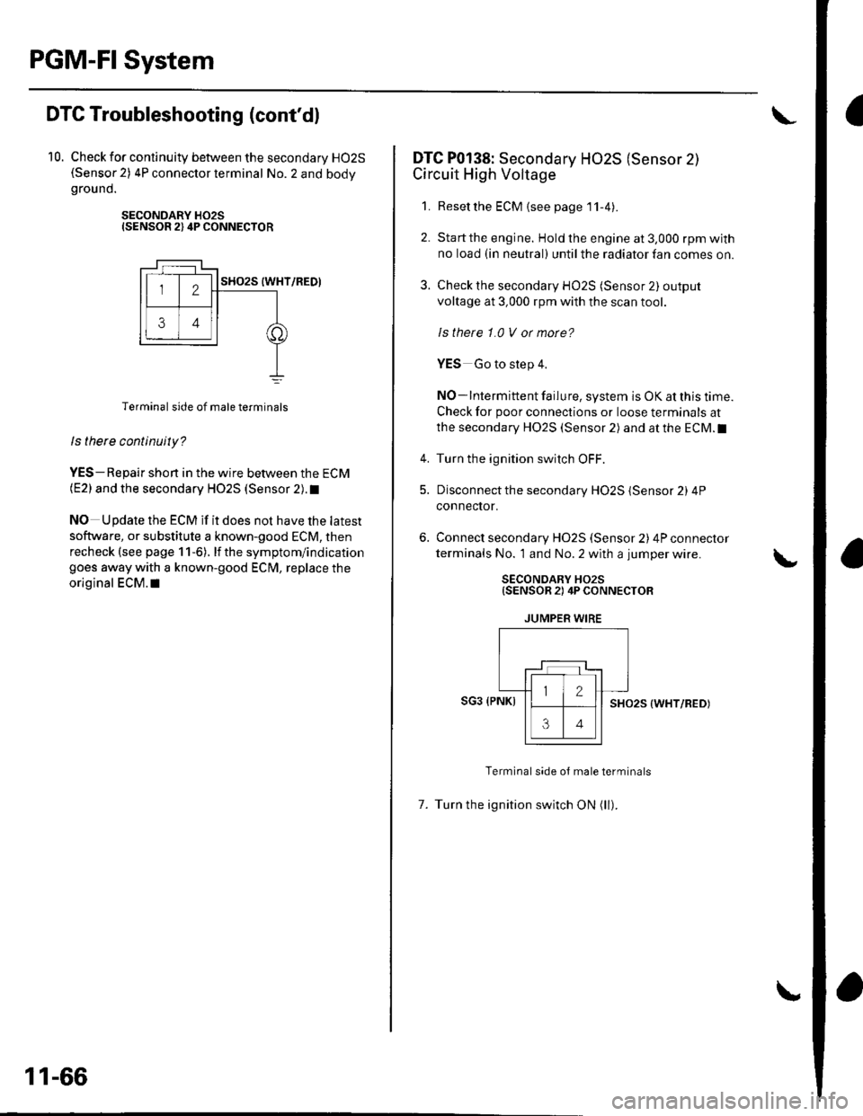
10. Check for continuity between the secondary HO2S(Sensor 2) 4P connector terminal No. 2 and bodygrou nd.
SECONDARY H02SISENSOR 2) 4P CONNECTOR
Terminal side of male terminals
ls there continuity?
YES-Repair shon in the wire between the ECM(E2) and the secondary HO2S (Sensor 2). t
NO Update the ECM if it does not have the latest
software, or substitute a known-good ECM, then
recheck (see page 1 1-6). lf the symptom/indication
goes away with a known-good ECM, replace the
original ECM.I|
11-66
DTC P0138: Secondary HO2S (Sensor 2)
Circuit High Voltage
1. Resetthe ECM {see page'11-4).
2. Startthe engine. Hold the engine at 3,000 rpm with
no load (in neutral) until the radiator fan comes on.
3. Check the secondary HO2S (Sensor 2) output
voltage at 3,000 rpm with the scan tool.
ls thete 1.0 V or morc?
YES Go to step 4.
NO-lntermittent failure, system is OK at this time.
Check for poor connections or loose terminals at
the secondary HO2S (Sensor 2) and at the ECM.I
4. Turn the ignition switch OFF.
5. Disconnect the secondary HO2S (Sensor 2) 4P
connector.
Connect secondary H02S (Sensor 2) 4P connector
terminals No. 1 and No. 2 with a jumper wire.
SECONDARY HO2S{SENSOR 2) 4P CONNECTOR
JUMPER WIRE
SG3 (PNKISHO25 (WHT/RED)
Terminal side oJ male terminals
7. Turn the ignition switch ON (ll).
Page 274 of 1139

8.Check the secondary H02S (Sensor 2) output
voltage with the scan tool,
ls there 1.0 V ot mote?
YES-Go to step 9.
NO Replace the secondary HO2S (Sensor 2).1
Turn the ignition switch OFF.
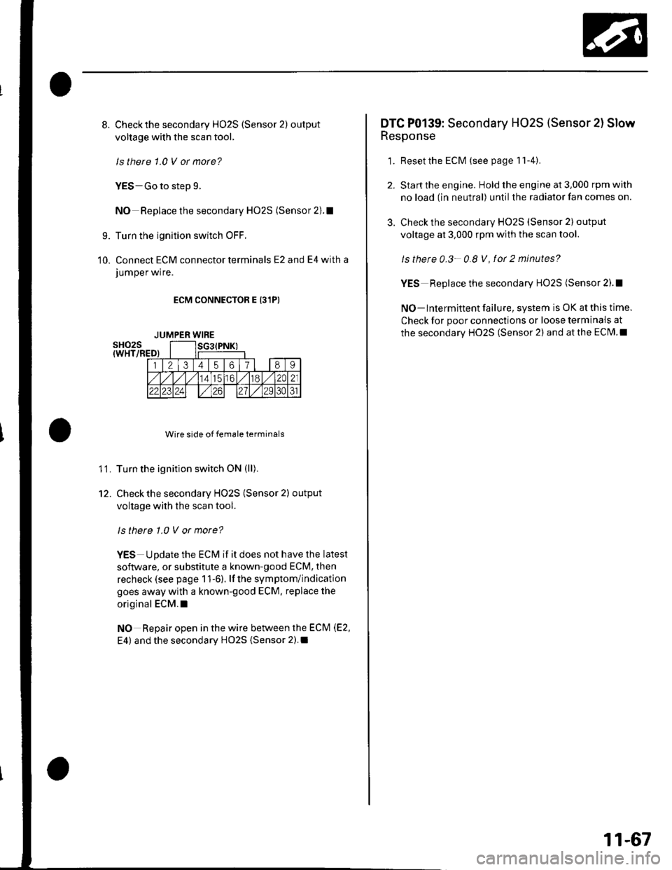
Connect ECM connector terminals E2 and E4 with a
JUmper wrre.
ECM CONNECTOR E 131PI
Wire side of female terminals
Turn the ignition switch ON (ll).
Check the secondary HO2S (Sensor 2) output
voltage with the scan tool.
ls there 1.0 V or more?
YES Update the ECM if it does not have the latest
soflware, or substitute a known-good ECM, then
recheck (see page 1 1-6). lf the symptom/indication
goes away with a known-good ECM. replace the
original ECM.I
NO Repair open in the wire between the ECM (E2,
E4) and the secondary HO2S {Sensor 2).I
9.
10.
11.
12.
JUMPER WIRE
3.
DTC P0139: Secondary HO2S (Sensor 2l Slow
Response
1. Resetthe ECM (see page 11-4).
Start the engine. Hold the engine at 3,000 rpm with
no load (in neutral) until the radiator fan comes on.
Check the secondary HO2S (Sensor 2) output
voltage at 3,000 rpm with the scan tool.
ls thete 0.3- 0.8 V, fot 2 minutes?
YES Replace the secondary HO2S (Sensor 2).!
NO- lntermittent failure, system is OK at this time.
Check for poor connections or loose terminais at
the secondary HO2S (Sensor 2) and at the ECM.I
11-67
Page 275 of 1139

PGM-FISystem
3.
DTC Troubleshooting (cont'dl
DTC P0141: Secondary HO2S (Sensor 2l
Heater Circuit Malfunction
1. Reset the ECM (see page 1 l-4)
2. Start the engine.
ls DTC P0141 indicated?
YES-Go to step 3.
NO-lntermittent failure, system is OK at this time.
Check for poor connections or loose terminals at
the secondary HO2S (Sensor 2) and at the ECM.I
Turn the ignition switch OFF.
Disconnect the secondary H02S (Sensor 2) 4P
connecror.
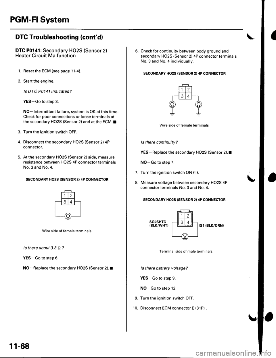
At the secondary HO2S (Sensor 2) side, measure
resistance between H02S 4P connector terminals
No.3 and No. 4.
SECONDARY HO2S (SENSOR 21 4P CONNECTOR
Wire side ol lemale terminals
ls there about 3.3 Q ?
YES Go to step 6.
NO- Replace the secondary HO2S (Sensor 2). t
5.
11-68
6. Check for continuity between body ground and
secondary H02S (Sensor 2) 4P connector terminals
No.3 and No. 4 individually.
SECONDARY HO2S {SENSOR 21 4P CONNECTOR
Wire side of female terminals
ls there continuity?
YES- Replace the secondary HO2S (Sensor 2).1
NO-Go to step 7.
Turn the ignition switch ON (ll).
Measure voltage between secondary H02S 4P
connector terminals No. 3 and No. 4,
SECONDARY HO2S (SENSOR 2l ilP CONNECTOR
t
7.
8.
9.
10.
s02sHTc{BLK/WHTIIG1 (BLK/ORN}
Terminal side of male terminals
ls there battery voltage?
YES Go to step 9.
NO Go to step 12.
Turn the ignition switch OFF.
Disconnect ECM connector E {31P)
Page 279 of 1139

PGM-FI System
IDTC Troubleshooting (cont'dl
DTC P0301: No. 1 Cylinder Misfire
DTC P0302: No. 2 Cylinder Misfire
DTC P0303: No. 3 Cylinder Misfire
DTC P0304: No. 4 Cylinder Misfire
1. After checking and recording the freeze data, reset
the ECM (see page 1 1-4). lf there is no freeze data of
the misfire, just clear the DTC.
2. Start the engine, and listen for a clicking sound
from the injector at the problem cylinder.
Does the injector click?
YES-Go to step 3.
NO-Go to step 30.
3. Turn the ignition switch OFF.
4. Exchange the ignition coil from the problem
cylinder with one from another cylinder,
5. Test-drive the vehicle for several minutes in the
range of the freeze data or under va rious
conditions if there was no freeze data.
6. Check for a DTC or a Temporary DTC with the scan
root.
ls DTC or Tempotaty DTC P0301, P0302, P0303
or P0304 ind icated?
YES Go to step 7.
NO Intermittent misfire due to poor contact at the
ignition coil connectors {no misfire at this time).
Make sure the coil connections are secure.l
11-72
8.
9.
1.
11.
Determine which cylinder(s) had the misfire.
Does the misf ire occur in the cylinder where the
ignition coil was exchanged?
YES Replace the faulty ignition coil.!
NO-Go to step 8.
Turn the ignition switch OFF.
Exchange the spark plug from the problem cylinder
with one from another cylinder.
Test-drive the vehicle for several minutes in the
range of the freeze data or under various
conditions if there was no freeze data.
Check for a DTC or Temporary DTC with the scan
Tool.
ls DTC ot Tempotary DTC P0301, P0302, P0303
or P0304 ind icated?
YES Go to step 12.
NO Intermittent misfire due to spark plug fouling,
etc. (no misfire at this time).1
Determine which cylinder(s) had the misfire.
Does the misl ire occur in the cylinder where the
spark plug was exchanged?
YES Replace the faulty spark plug.l
NO Go to step 13.
Turn the ignition switch OFF.
Exchange the lnjector from the problem cylinder
with one from another cylinder.
Let the engine idle for 2 minutes.
10.
14.
t5.