2002 HONDA CIVIC fuel pressure sensor
[x] Cancel search: fuel pressure sensorPage 229 of 1139
![HONDA CIVIC 2002 7.G Workshop Manual Fuel and Emissions Systems
System Descriptions (contdl
ECM lnputs and Outputs at Connector E (31P}
L
u
1iMoFPR
2sr-{]zs3LG34SG3
6$1025HTC
1M RLY
8AFSHTCR
I
14FTP15ELD
16EPSLD
18ACC20Z/VBS21VSV
22BKSW HONDA CIVIC 2002 7.G Workshop Manual Fuel and Emissions Systems
System Descriptions (contdl
ECM lnputs and Outputs at Connector E (31P}
L
u
1iMoFPR
2sr-{]zs3LG34SG3
6$1025HTC
1M RLY
8AFSHTCR
I
14FTP15ELD
16EPSLD
18ACC20Z/VBS21VSV
22BKSW](/manual-img/13/5744/w960_5744-228.png)
Fuel and Emissions Systems
System Descriptions (cont'dl
ECM lnputs and Outputs at Connector E (31P}
L
u
1iMoFPR
2sr-{]zs3LG34SG3
6$1025HTC
1M RLY
8AFSHTCR
I
14FTP15ELD
16EPSLD
18ACC20Z/VBS21VSV
22BKSW23K-LINE24SEFMJ26NEP
21rMoCD
29scs30WEN31MIL
Wire side of female terminals
NOTE: Standard battery voltage is '12 V.
TerminalnumberWire colorferminal nameDescription Signal
GRNI/ELIMO FPR (IMMOBILIZERFLJEL PUMP RELAYIDrives PGM Fl main relay 20Vfor2 seconds after turning ignition switch ON{ll). then batterv voltaoe2WHT/REDSHO2S (SECONDARYHEATED OXYGEN SENSOR(SECONDARY HO2S),SENSOR 2r
Detects secondary HO2S{sensor 2) signalWith throttle Jully opened from idle with fullywarmed up engine: above 0.6VWith throttle quickly closed: below 0.4 V
3BRN/YELLG3 (LOGIC GROUND)cround forthe ECM/PCMcontrolcircuitLess than 1.0 V at all times
4PNKSG3 {SENSOR GBOUND)Sensor oroundLess than 1.0 V at all times5YEUELUVCC3 {SENSOR VOLTAGE)Provides sensor voltageWith ignition switch ON (ll): about 5 VWith ionition switch OFF: about 0 V6BLKATr'HTSO25HTC (SECONDARYHEATED OXYGEN SENSOR(SECONDARY H02S)HEATER CONTROL)
Drives secondary HO2SheaterWith ignition switch ON (ll): baftery voltageWilh fullv warmed up engine running: dul,controlled
1REDA/ELMRLY (PGM.FI MAINRELAY}Drives PGM-Flmain relay 1Power source forthe DTCWith ignition switch ON (ll): about 0 VWith ignition switch OFF: battery voltage
IORNAFSHTCR {AIR FUEL BATIO(Iy'F)SENSOR HEATERCONTROL RELAY)
Drives air fuel ratio sensorheater relayWith ignition swirch ON {ll): 0 V
IYEUBLKIGl (IGNITION SIGNAL)Detecrs ignition signalWith ignition switch ON (ll): battery voltageWith iqnition switch OFF: about 0 V't4LT GRNFIP lFUEL TANKPRESSURE (FTP) SENSOR)Detects FTP sensor signalWith ignition switch ON (ll) and fuel fill cap open:about 2.5 VGRN/REDELD (ELECTRICAL LOADDETECTOF)Detects ELD signalWith ignition swjtch ON itt):aOoutO.t V l-gV(deDendino on electrical load)LT GRN/8LKEPSLD (ELECIRICALPOWEB STEEBING LOADDETECT)
Detects Power steering loadsrgnalAt idle with steering wheel in straight aheadposition: about 0 VAt idle with steering wheelatfull lock: momentary
'18REDACC (Ay'C CLUTCH RELAY)Drives P,/C clutch relayWith compressor ON: about 0 VWith comoressor OFF: batterv voltaoe
11-22
\-
Page 232 of 1139

Vacuum Hose Routing
I
O AIR FUEL RATIO IA/F) SENSOR {SENSOR 1}O SECONDARY HEATED OXYGEN SENSORISECONDARY HO2S} {SENSOR 2}
O MANIFOLD ABSOLUTE PRESSURE (MAPI SENSORO ENGINE COOLANT TEMPERATURE {ECT) SENSORO INTAKE AIR TEMPERATURE (IAT) SENSORO CRANKSHAFT POSITION (CKP) SENSORO KNOCK SENSORO CAMSHAFT POSITION (CMPI SENSOR BITOP DEAD CENTER ITDC) SENSOR)
O CAMSHAFT POSITION ICMPI SENSOR A@ IDLE AIR CONTROL (IACI VALVEO THRONLE BODY.O INJECTOR@ FUEL PULSATION OAMPER[I FUEL FILTER@ FUEL PRESSURE REGULATOR@ FUEL PUMP@ FUEL TANK
@ RESONATOR(9 AIR CLEANER@ POSITIVE CRANKCASE VENTILATION {PCVI VALVE@ THREE WAY CATALYTIC CONVERTER@ EVAPORATIVE EMISSION {EVAPI CANISTER@ EVAPORATIVE EMISSION {EVAP) CANISTERPURGE VALVE{} EVAPORATIVE EMISSION (EVAPI CANISTERVENT SHUT VALVE{' EVAPORATIVE EMISSION {EVAP) TWO WAY VALVE@ EVAPORATIVE EMISSION IEVAPI BYPASSSOLENOID VALVE@ FUEL TANK PRESSURE (FTP) SENSOR@ EVAPORATIVE EMISSION IEVAP} VALVE@ FUEL TANK VAPOR CONTROL VALVE60) FUEL TANK VAPOR RECIRCULATION VALVEO INTAKE AIR BYPASS CONTROL THERMAL VALVE
(cont'd)
11-25
Page 233 of 1139

Fuel and Emissions Systems
System Descriptions (cont'd)
PGM-FI System
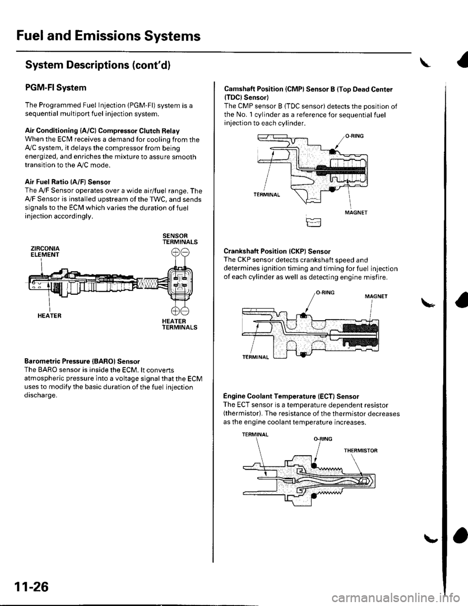
The Programmed Fuel Injection (PGM-Fl) system is a
sequential multiport fuel injection system.
Air Conditioning {A/C) Compressor Glutch Relay
When the ECfM receives a demand for cooling from the
Ay'C system, it delays the compressor from being
energized, and enriches the mixture to assure smooth
transition to the AVC mode.
Air Fuel Ratio lA/Fl Sensor
The Ay'F Sensor operates over a wide airlfuel range. The
Ay'F Sensor is installed upstream of the TWC, and sends
signals to the ECM which varies the duration of fuel
injection accordingly.
SENSORTERMINALS
HEATERTERMINALS
Barometric Pressure {BAROI Sensor
The BARO sensor is inside the ECM. lt convens
atmospheric pressure into a voltage signal that the ECM
uses to modify the basic duration of the fuel injection
discharge.
ztRcoNtaELEMENT
HEATER
11-26
\,
Camshaft Position (CMPI Sensor B (Top Dead Center(TDCI Sensor)
The CMP sensor B (TDC sensor) detects the position of
the No. 1 cylinder as a reference for sequential fuel
injection to each cylinder.
Crankshaft Position (CKPI Sensor
The CKP sensor detects crankshaft soeed and
determines ignition timing and timing for fuel injection
of each cylinder as well as detecting engine misfire.
Engine Coolant Temperature (ECT) Sensor
The ECT sensor is a temperature dependent resistor(thermistor). The resistance of the thermistor decreases
as the engine coolant temperature increases.
MAGNET
TERMINAL
Page 234 of 1139

lgnition Timing Control
The ECM contains the memory for basic ignition timing
at various engine speeds and manifold absolute
pressure. lt also adjusts the timing according to engine
coolant temperature.
Iniector Timing and Duration
The ECM contains the memory for basic discharge
duration at various engine speeds and manifold
pressures. The basic discharge duration, after being
read out from the memory, is further modified by
signals sent from various sensors to obtain the final
discharge duration.
By monitoring long term fuel trim, the ECM detects long
term malfunctions in the fuel system and sets a
Diagnostic Trouble Code {DTC).
Intake Air Temperature (lAT) Sensor
The IAT sensor is a temperature dependent resistor
{thermistor). The resistance of the thermistor decreases
as the intake air temDerature increases.
Knock Sensor
The knock control system adjusts the ignition timing to
minimize knock.
PIEZOCERAMIC
Malfunction Indicator Lamp lMlLl Indication {ln relation
to Readiness Codes)
The vehicle has certain "readiness codes" that are part
of the on-board diagnostics for the emissions systems.
lf the vehicle's baftery has been disconnected or gone
dead. if the DTCS have been cleared, or if the ECM has
been reset. these codes are set to incomplete. In some
states, part of the emissions testing is to make sure
these codes are set to comDlete. lf all of them are not
set to complete, the vehicle may fail the test and the
test cannot be finished.
To check if the readiness codes are set to complete,
turn the ignition switch ON (ll). but do not start the
engine.TheMILwill comeonforlS 20seconds. lf it
then goes off, the readiness codes are set to complete,
lf it blinks severaltimes, one or more readiness codes
are not set to comolete. To set each code, drive the
vehicle or run the engine as described in the
procedures to set them in this section (see page 1 1-46).
Manifold Absolute Pressure {MAP) Senso]
The MAP sensor converts manifold absolute pressure
into electrical signals to the ECM.
SENSOR UNIT
(cont'd)
11-27
Page 242 of 1139

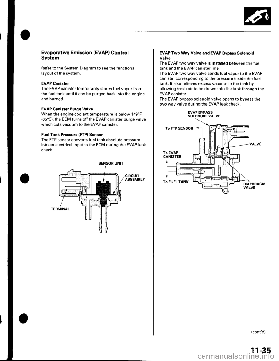
Evaporative Emission (EVAPI Control
System
Refer to the System Diagram to see the functional
layout of the system.
EVAP Canister
The EVAP canister temporarily stores fuel vapor from
the fuel tank until it can be purged back into the engine
and burned.
EVAP Canister Purge Valve
When the engine coolant temperatu re is below 149'F(65'C), the ECM turns off the EVAP canister purge valve
which cuts vacuum to the EVAP canister.
FuelTank Pressure (FTP) Sensor
The FTP sensor converts fueltank absolute pressure
into an electrical inputto the ECM during the EVAP leak
cnecK.
SENSOR UNIT
EVAP Two Way Valve and EVAP Eyp8s Solenoid
Valve
The EVAP two way valve is installed between the fuel
tank and the EVAP canister line.
The EVAP two way valve sends fuel vapor to the EVAP
canister corresponding to the pressure inside the tuel
tank. lt also relieves excess vacuum in the tank by
allowing fresh air to be drawn into the tank through the
EVAP canister.
The EVAP bypass solenoid valve opens to bypass the
two way valve during the EVAP leak check.
EVAP BYPASSSOLENOID VALVE
VALVE
(cont'd)
To FUEL TANK
11-35
Page 256 of 1139
![HONDA CIVIC 2002 7.G Workshop Manual PGM-FI System
Component Location Index
CAMSHAFT POS]TION {CMP) SENSOR B(TOP DEAD CENTER (TDC}SENSORITroubleshootina. oaoe 1 1-95Replacement, p;ge 1-1.1 14
ELECTRICAL LOADDETECTOR {ELDITroubleshooting, HONDA CIVIC 2002 7.G Workshop Manual PGM-FI System
Component Location Index
CAMSHAFT POS]TION {CMP) SENSOR B(TOP DEAD CENTER (TDC}SENSORITroubleshootina. oaoe 1 1-95Replacement, p;ge 1-1.1 14
ELECTRICAL LOADDETECTOR {ELDITroubleshooting,](/manual-img/13/5744/w960_5744-255.png)
PGM-FI System
Component Location Index
CAMSHAFT POS]TION {CMP) SENSOR B(TOP DEAD CENTER (TDC}SENSORITroubleshootina. oaoe 1 1-95Replacement, p;ge 1-1.1 14
ELECTRICAL LOADDETECTOR {ELDITroubleshooting,page 1'l -92
INTAKE AIR TEMPERATURE{IATI SENSORTroubleshooting,page 'l'l-55
Replacement, page 11-'l 15
f- \
rl
KNOCK SENSORTroubleshooting, page 1 1-77Beplacement, page 11 115
ENGINE COOLANT TEMPERATURE(ECTI SENSORTroubleshooting, page 1 1-57Replacement, page 11 114
MANIFOLD ABSOLUTE PRESSURE(MAP) SENSORTroubleshooting, page 1 1-52
THROTTLE POSITIONITP} SENSORTroubleshooting, page 11-60CRANKSHAFT POSITIONICKPISENSORTroubleshooting, page'l 1-78Beplacement, page 1 1-'l 16
AIR FUEL RATIO {A/F)SENSOR ISENSOR 1}Trorrbleshooting, page 1 1-84Replacement, page 11- 1 13
{cont'd)
ii'- r'1
.I11 ---:,I''.!,i(..,.?:fir-J-
.....,..:--.
11-49
Page 277 of 1139

PGM-FI System
DTC Troubleshooting (cont'dl
DTC P0171: Fuel System Too Lean
DTC P0172: Fuel System Too Rich
NOTE: lf some of the DTCS listed below are stored at
the same time as DfC PO17'l and/ot PO172,
troubleshoot those DTCS first, then recheck for P0171
andlot P0112.
P0107, P0108. P1 128. P1 129: Manifold absolute
pressure (MAP) sensor
P1 162. P1 166, P 1 167: 4,,/F sensor (Sensor 1 ) heater
P0137, P0138: Secondary HO2S (Sensor 2)
P014'l: Secondary HO2S (Sensor 2) heater
P1259: VTEC system
1. Check the fuel pressure (see page 11-'145).
ls luel pressure OK?
YES Go to step 2.
NO Check these items:
. lf the pressure is too high, replace the fuel
pressure regulator (see page 11-152).1. lf the pressure istoo low.checkthefuel pump,
the fuel feed pipe, the fuel filter, and replace the
fuel pressure regulator (see page 11-152).I
2. Start the engine. Hold the engine at 3,000 rpm with
no load (in neutral) until the radiator fan comes on.
11-70
3. Turn the ignition switch OFF.
4. With a vacuum pump, apply vacuum to the
evaporative emission (EVAP) canister purge valve
(A) from the evaporative emission (EVAP) canister
side.
' A973AX-041-XXXXX
Does it hold vacuum?
YES-Check the engine valve clearances and adjust
if necessary, lf the valve clearances are OK, replace
the injectors (see page 1 1-1 1 1).1
NO-Replace the EVAP canister purge valve.l
Page 278 of 1139

DTC P0300: Random Misfire and Any Combination of the Following:
DTC P0301: No. 1 Cylinder Misfire
DTC P0302: No. 2 Cvlinder Misfire
DTC P0303: No, 3 Cvlinder Misfire
DTC P0304: No. 4 Cvlinder Misfire
NOTE:. lfthe misfiring is frequent enough to trigger detection of increased emissions during two consecutive driving cycles.
the MIL will come on, and DTC P0300 (and some comlrination of P0301 through P0304) will be stored.. lf the misfiring is frequent enough to damage the catalyst, the MIL will blink whenever the misfiring occurs, and OTC
P0300 (and some combination of P0301 through P0304) will be stored. When the misfirlng stops, the MIL will remain
on.
1. Troubleshoot the following DTCs first if any of them were stored along with the random misfire DTC(s):
P0'107, P0108, P1128, P1129r N4anifold absolute pressure (MAP) sensor
P0111. P0'172t Fuel svstem
P0335. P0336: Crankshaft position (CKP) sensor
P0505: ldle control system
P1 149, Pl 162, P1 163, P1 164, P 1 165: Air fuel ratio (Ay'F) sensor
P1259: VTEC system
P1361, P1362: Camshaft position (CMP) sensor B {Top dead center (TDC) sensor)
P1519: ldle air control (lAC) valve
2. Test-drive the vehicle to verify the symptom.
3. Findthesymptom inthechart below, and dothe related procedures in the order listed until you find the cause.
SymptomProcedure(slAlso check foi:
Random misfire only
at low RPM and
under load
Check fuel pressure (see page 1 1-145).. Low compressron.. Low quality fuel.
Random misfire only
du ring acceleration
Check fuel pressure (see page 11-145).Malfunction in the
VTEC system (see page
1'�t-123).
Random misfire at
high RPM, under
load, or under
random conditions
Check fuel pressure (see page 11-145).Correct engine valve
clearances (see page 6-
91.
11-71