Page 907 of 1139
Exterior Lights
Daytime Running Lights Control Unit Input Test - Canada
The DRL indicator light in the gauge assembly will come on when you turn the ignition switch to ON (ll) with the
headlight switch off and the parking brake se1. lt should go off when you turn on the headlight switch and release the
parking brake. lf it comes on at any other time, do the control unit input test.
NOTE: When the daytime running lights are on, the high beam indicator will glow at half its normal intensity.
1. Remove the driver's dashboard lower cover (see page 20-60).
2, Disconnectthe l4Pconnector(A) from thedaytime running lightscontrol unit(B).
RED/BLUGNN/BLKRED/BLUGRN/BLKGRN/ORN
BLU/RED RED/YEL YEL/RED
Inspect the connector and socket terminals to be sure they are all making good contact.
. lf the terminals are bent, loose orcorroded, repairthem as necessary, and recheckthe system.
' lf the terminals look OK, go to step 4.
\
22-76
Page 911 of 1139
Exterior Lights
4.
5.
Combination Light Switch Test/Replacement
1. Remove the driver's dashboard lower cover (see page 20-60).
2. Remove the steering column covers (see page 17-9).
3, Disconnectthe l6Pconnector(A) f rom the combination light switch (B).
Remove the tlvo screws, then slide out the combination light switch.
Inspect the connector terminals to be sure they are all making good contact.
. lf the terminals are bent, loose or co rroded, repa ir them as necessa ry, a nd recheck the system..lftheterminalslookOK,checkforcontinuitybetweentheterminalsineachswitchpositionaccordingtothe
tables.- lf the continuity is not as specified, replace the switch.
Light switch:
Telmint
Position451213
Headlight switch
OFF
LOWo--
HIGHo--
Passing switch
OFF
ONo-
Turn signalswitch:
Terminal
Position21011
LEFT----o
NEUTRAL
RIGHTo--
22-80
Page 1111 of 1139

sRs
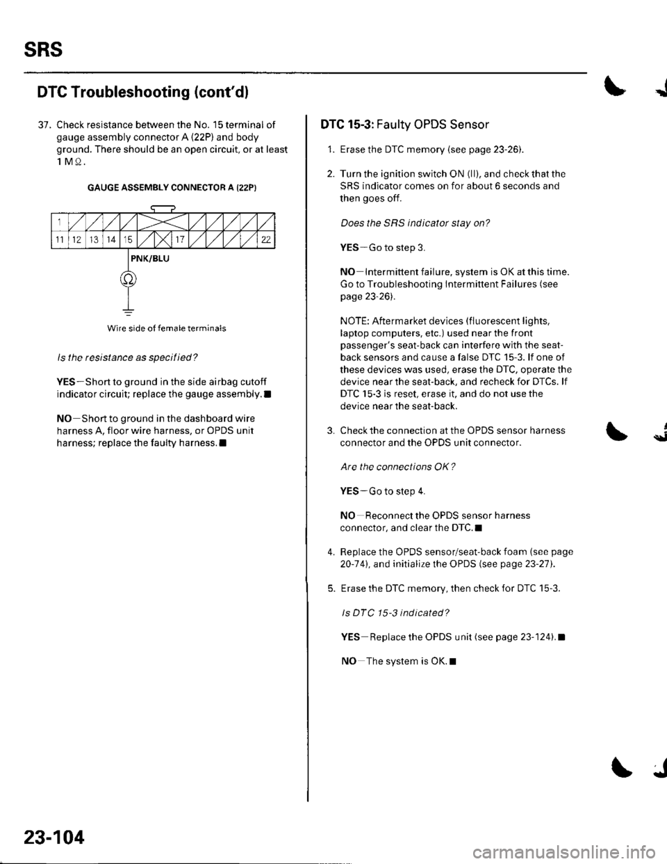
DTG Troubleshooting (cont'dl
37. Check resistance between the No. 15 terminal of
gauge assembly connector A (22P) and body
ground. There should be an open circuit, or at least
1M0.
GAUGE ASSEMBLY CONNECTOR A I22PI
ls the resistance as specified?
YES-Short to ground in the side airbag cutoff
indicator circuit; replace the gauge assembly.l
NO Short to ground in the dashboard wire
harness A, floor wire harness, or OPDS unit
harness; replace the faulty harness.l
Wire side of female terminals
23-104
J
DTC 15-3: Faulty OPDS Sensor
1. Erase the DTC memory {see page 23-261.
2. Turn the ignition switch ON (ll), and check that the
SRS indicator comes on for about 6 seconds and
then goes off.
Does the SRS indicator stay on?
YES-Go to step 3.
NO Intermittent failure, system is OK at this time.
Go to Troubleshooting Intermittent Failures (see
page 23-26).
NOTE: Aftermarket devices (fluorescent lights,
laptop computers, etc.) used near the front
passenger's seat-back can interfere with the seat-
back sensors and cause a false DTC 15-3. lf one of
these devices was used, erase the DTC, operate the
device near the seat-back, and recheck for DTCs. lf
DTC 15-3 is reset, erase it, and do not use the
device near the seat-back.
3.
4.
Check the connection at the OPDS sensor harness
connector and the OPDS unit connector.
Are the connections OK?
YES-Go to step 4.
NO Reconnect the OPDS sensor harness
connector, and clear the DTC.I
Replace the OPDS sensor/seat-back foam (see page
20-141, and initialize the OPDS (see page 23-27).
Erase the DTC memory, then check for DTC 15-3.
ls DTC 15-3 indicated?
YES Replace the OPDS unit (see page 23-1241.a
NO The system is OK.l
{