Page 583 of 1139

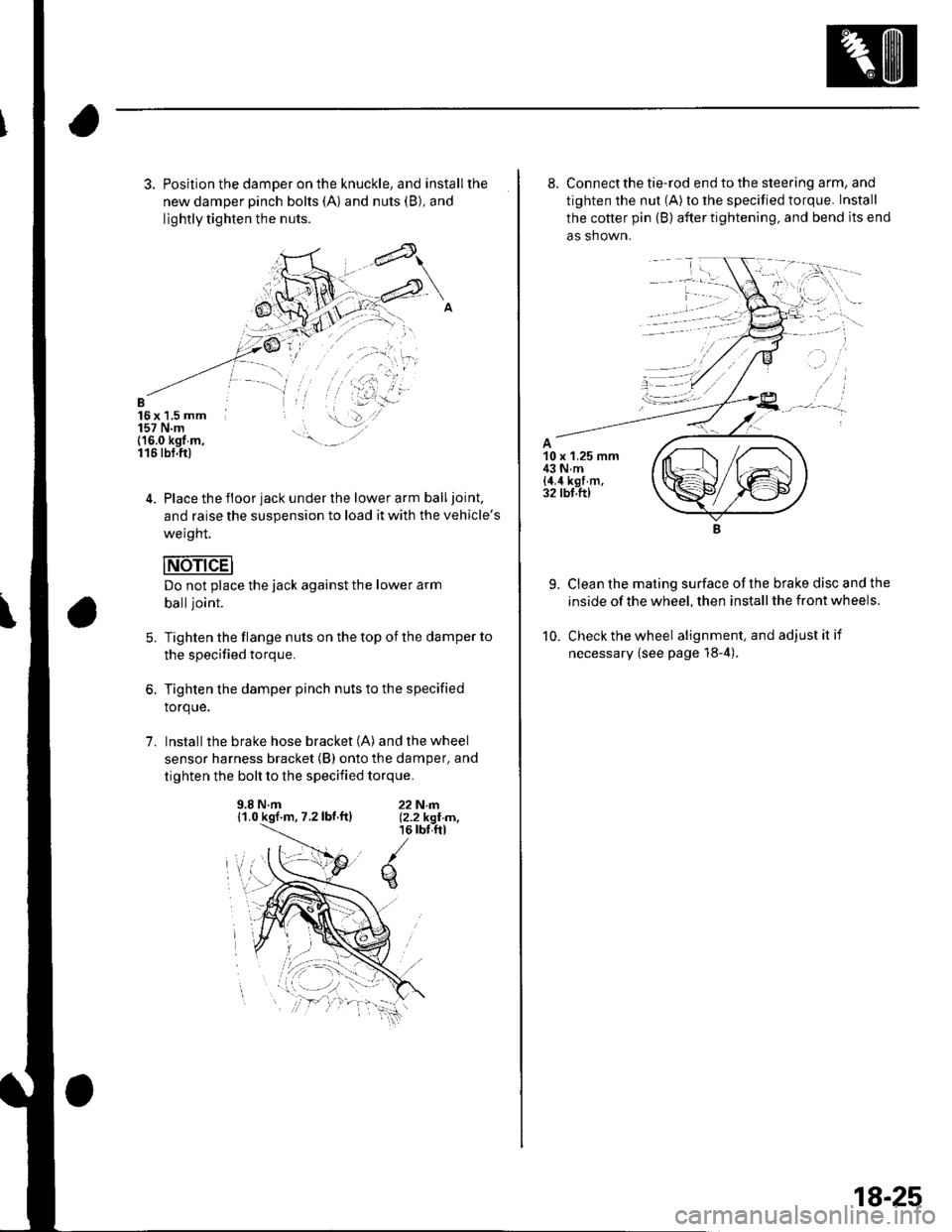
3. Position the damper on the knuckle, and installthe
new damper pinch bolts (A) and nuts (B), and
lightly tighten the nuts.
B16x 1,5 mm157 N.m(16.0 kgt m,116 tbt.ftl
4. Place the floor jack under the lower arm balljoint,
and raise the suspension to load it with the vehicle's
weight.
Do not place the jack against the lower arm
balljoint.
Tighten the flange nuts on the top of the damper to
the specified torque.
Tighten the damper pinch nuts to the specified
torque.
Install the brake hose bracket (A) and the wheel
sensor harness bracket (B) onto the damper, and
tighten the bolt to the specified torque.
5.
1.
9.8 N.m11.0 kgf.m, 7.2lbf.ftl22N|rl.12.2 kgI m,16 rbr,ftl
q
8. Connect the tie-rod end to the steering arm, and
tighten the nut (A) to the specified torque. Install
the cotter pin (B) after tightening, and bend lts end
as shown.
9. Clean the mating surface ofthe brake disc and the
inside of the wheel, then install the front wheels.
10. Check the wheel alignment, and adjustitif
necessary {see page 18-4).
18-25
Page 586 of 1139

Rear Suspension
Hub Bearing Unit Replacement
(cont'd)
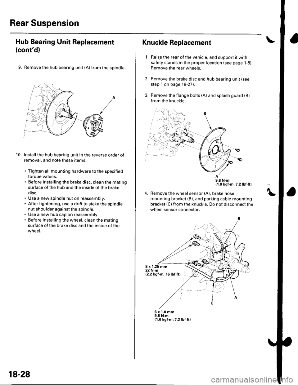
9. Remove the hub bearing unit (A) from the spindle.
Install the hub bearing unit in the reverse order of
removal, and note these items:
. Tighten all mounting hardware to the specified
torque values,. Before installing the brake disc, clean the mating
surface ot the hub and the inside of the brake
disc.. Use a new spindle nut on reassembly.. After tightening, use a drift to stake the spindle
nut shoulder against the spindle.. Use a new hub cap on reassembly.. Before installing the wheel, clean the mating
surface of the brake disc and the inside of the
wneel.
10.
,=,,,
18-28
Raise the rear of the vehicle, and suppon it with
safety stands in the proper location (see page 1-8).
Remove the rear wheels.
Remove the brake disc and hub bearing unit (see
step 1 on page 18-27).
Remove the flange bolts (A) and splash guard (B)
from the knuckle.
11.0 kgf.m, 7.2 lbf ft)
4. Remove the wheel sensor(A), braKe nose
mounting bracket (B), and parking cable mounting
bracket (C) from the knuckle. Do not disconnect the
wheel sensor connector.
8 x 1.25 mm22 N.m{2.2 kgf m, 16 lbf ftl
Knuckle Replacement
1.
6x1.0mm9.8 N,m{I.0 kgt.m,7.2 lbf ft)
tt
Page 590 of 1139

Rear Suspension
Upper Arm Removal/lnstallation
1.Raise the rear of the vehicle, and support lt with
safety stands in the proper location (see page 1-8).
Remove the rear wheels.
Place a floor jack under the trailing arm, and
support the suspensron.
Remove the flange bolt (A) and wheel sensor
harness bracket (B).
8 x 1.25 mm22 N.m (2.2 kgf.m,16 rbf.ft)
Remove the flange bolts (A), and remove the upper
arm {B).
12 x 1.25 mm59 N.m {6.0 kgf.m,ir3 lbf.ft)12 x 1.25 mm59 N.m 16.0 kgf m,43 tbf.ft)
18-32
5. Installthe upper arm in the reverse order of
renloval, and note these items:
. First install allthe suspension components and
lightly tighten the bolts and nuts, then place ajack under the trailing arm, and raise the
suspension to load it with the vehicle's weight
before fully tightening the bolts and nuts to the
specified torque values.. Tighten allthe mounting hardware to the
specified torque values.' Before installing the wheel, clean the mating
surface of the brake disc and the inside of the
wheel.. Check the wheel alignment, and adjust it if
necessary (see page 18-4).
Page 610 of 1139

Master Cylinder Replacement
NOTE: Do not spill brake fluid on the vehicle; it may
damage the paint; if brake fluid does contact the paint,
wash it off immediately with water,
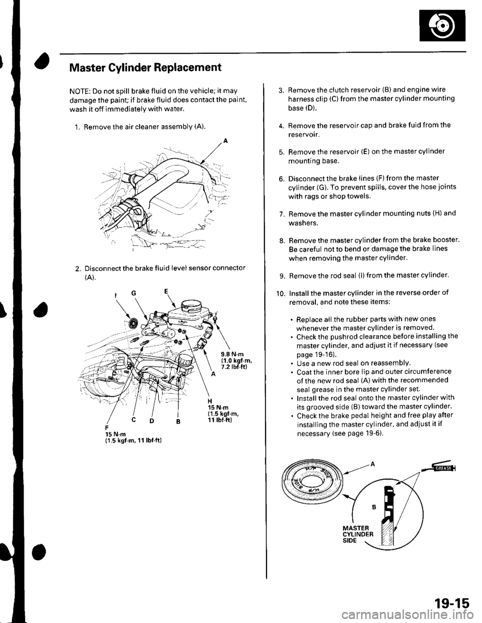
1, Remove the air cleaner assembly (A).
2, Disconnect the brake fluid level sensor connector
(A).
15 N.m{1.5 kgt.m, 11 lbt.ft)
3. Remove the clutch reservoir (B) andenginewire
harness clip (C)from the master cylinder mounting
base (D).
4. Remove the reservoir cap and brake fuid from the
reservoir.
5. Remove the reservoir (E) on the master cylinder
mountrng Dase.
6, Disconnect the brake lines (F)from the master
cylinder (G). To prevent spills, cover the hose joints
with rags or shop towels.
7. Remove the master cylinder mounting nuts {H) and
washers.
8. Remove the master cylinder from the brake booster.
Be careful not to bend or damage the brake lines
when removing the master cylinder.
9. Remove the rod seal (l) from the master cylinder.
10. Installthe master cylinder in the reverse order of
removal, and note these items:
. Replace all the rubber parts with new ones
whenever the master cylinder is removed.
. Check the pushrod clearance before installing the
master cylinder. and adjust it if necessary (see
page 19-16).. Use a new rod seal on reassemblY. Coat the inner bore lip and outer circumference
of the new rod seal {A) with the recommended
seal grease in the master cylinder set.
. Installthe rod seal ontothe master cylinder with
its grooved side (B)toward the master cylinder.
. Check the brake pedal height and free play after
installing the master cylinder, and adjust it if
necessary (see page 19-6).
19-15
Page 623 of 1139
Brakes
Conventional Brake Components ................ 1 9-1
ABS (Anti-lock Brake System) Components
Comoonent Location lndex .............,........................... 19-30
General Troubleshooting Information ....................... 19-31
DTC Troubleshooting Index .............. 19-34
Symptom Troubleshooting Index ...,........................... 19-35
System Description ................. ........... 19-36
Circuit Diagram ......... 19-42
DTC Troubleshooting ............... .......... 19-45
ABS Indicator CircuitTroubleshooting ...................... 19-52
Brake System Indicator Circuit
Troubleshooting ...................... ....... 19-55
ABS Modulator-Control Unit Removal and
lnstallation ............. 19-57
Wheel Sensor Insoection ................... 19-59
Wheel Sensor Reolacement .............. 19-59
Page 638 of 1139
ABS Components
q,
CONNECTOR A {12P)BRAKE PEDAL POSITIONSWITCH 4P CONNECTOR
Circuit Diagram (cont'd)
UNDER-HOOD FUSE/RELAY BOX CONNECTORSCONNECTOR A {12P) CONNECTOR B {2P}
UNDER.DASH FUSE/RELAY BOX CONNECTORSCONNECTOR I {5P)CONNECTOR K I17P)MULTIPLEX CONTROLUNIT 13P CONNECTOR
CONNECTOR B I22PI
1l2l3l,/15
GAUGE ASSEMBLY CONNECTORS
CONNECTOR A I22P)
WHEEL SENSOR 2P CONNECTORS
FRONT
J --T:-l Ltqtt/)l'l L_.:-:J r\-r-----Tr'e:l
RIGHT.REAR LEFT-REAR
tslTt?t /J 1T-1\I tL | rlziJ
Terminal side of male lerminals
ABS CONTROL UNIT 3IP CONNECTOR
OATA LINK CONNECTOR {16P)
Terminal side of female terminals
Wire side of female terminals
1234567
810111213141511
123,/ ,/
67891011n213
1245678I11121415
161118192021/1,/1,/vl,/l
/t,/t/t,/t/
19-44
Page 653 of 1139
Wheel Sensor Inspection
1.
2.
Inspect the front and rear pulsers for chipped or
damaged teeth.
Measure the air gap between the wheel sensor and
the pulser all the way around while rotating the
pulser. Remove the rear brake disc to measure the
gap on the rear wheel sensor. lf the gap exceeds
1.0 mm (0.04 in.), check for a bent suspension arm.
Standard:
Front; 0.4- 1.0 mm (0.02-0.04 in.)
Rear: 0.2 1.0 mm (0.01 0.04 in.l
Front:
0.4 '1.0 mm10.02 0.0'l in.l
I
t
Bear:
0.2 1.0 mm{0.01 0.04 in.}
Wheel Sensor Replacement
NOTE: Inslall the sensors carefully to avoid twisting the
wtres.
Front:
6 mm BOLT9.8 N.m{1.0 kgf.m,7.2lbf.ftl
6 mm BOLT9.8 N.m{1.0 kgf.m,7.2 lbf.ftl
Rear:
6 mm BOLT9.8 N.m11.0 kgf.m,7.2 lbf.ft)
WHEEL SENSOR
6 mm BOLT9.8 N.m(1.0 kgf'm,7.2 rbr.ft)
19-59
Page 851 of 1139

Connectors and Harnesses
Engine Compartment Wire Harness (Left branch)
AirJuel (A,,/F) ratio sensorBrake fluid level switchCondenser fan motorCruise control actuatorELD unitFog light connectorLeft front ABS wheel sensorLeft front airbag sensorLeft front parking lightLeft front side marker lightLeft lrontturn signal lightLeft headlightLeft hornRadiator fan motorRadiator fan switchSecondary heated oxygen (SHO2S)
Test tachometer connectorWindshield wiper motorUnder'hood fuse/relay boxconnector A {see page 22-44)Under-hood f use/relay boxconnector B (see page 22-44)Under hood fuse/relay boxconnector C (see page 22-44)Under hood fuse/relay boxconnector D (see page 22 44)Under-hood fuse/relay box
Front of engine companmentLeft side of engine compartmentLeft side of engine compartmentLeft side o{ engine compartmentFront of engine compartmentUnder right side of cowl coverUnder'hood f use/relay boxLeft side of engine compartmentLeft side of engine companmentBehind left side of front bumperBehind left headlightBehind left side of front bumperEehind left headlightBehind left headlightBehind front bumperLeft side of engine compartmentFront of engine compartmentLeft side of engine compartment
Left side of engine companmentL.Jnder left side of cowl coverL.Jnder hood fuse/relay box
L.Jnder hood fuse/relay box
L.Jnder'hood f use/relay box
underhood fuse/relay box
Under-hood fuse/relay box
24222
2519
12
17
13202123
3
117
I
10
5
6
l2
2243,l
222223l224
252
5
12
Connector to Harness Index (cont'dl
\
22-20