Page 118 of 1139

Gylinder Head Removal
NOTE:. Use fender covers to avoid damaging painted
surfaces.
To avoid damage, unplug the wiring connectors
carefully whlle holding the connector portion.
To avoid damaging the cylinder head, wait until the
engine coolant temperature drops below 100'F (38"C)
betore loosening the cylinder head bolts.
Mark all wiring and hoses to avoid misconnection.
Also, be sure that they do not contact other wiring or
hoses, or interfere with other parts.
'1.
2.
3.
Drain the engine coolant (see page 10-6).
Remove the drive belt (see page 4-26).
Remove the intake manifold {see page 9-3).
Remove the air cleaner housing (see step 7 on page
5-2t.
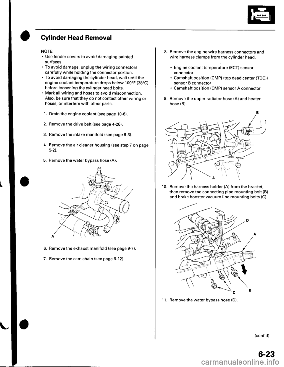
5. Remove the water bypass hose (A).
Remove the exhaust manifold (see page 9-7
Remove the cam chain (see page 6-12).
6.
7.
).
8. Remove the engine wire harness connectors and
wire harness clamps from the cylinder head.
. Engine coolant temperature (ECT) sensor
conneclor. Camshaft position (Cl\4P) (top dead center (TDC))
sensor B connector. Camshaft posilion (CMP) sensor A connector
9. Remove the upper radiator hose (A) and heater
hose (B).
'10. Remove the harness holder (A)from the bracket,
then remove the connecting pipe mounting boh {B)
and brake booster vacuum line mounting bolts {C).
(cont'd)
1 1. Remove the water bvpass hose (D).
6-23
Page 135 of 1139

Cylinder Head
8.
Cylinder Head lnstallation (cont'd)
7.Apply engine oil to the bolt threads and under thebolt heads of all the cylinder head bolts.
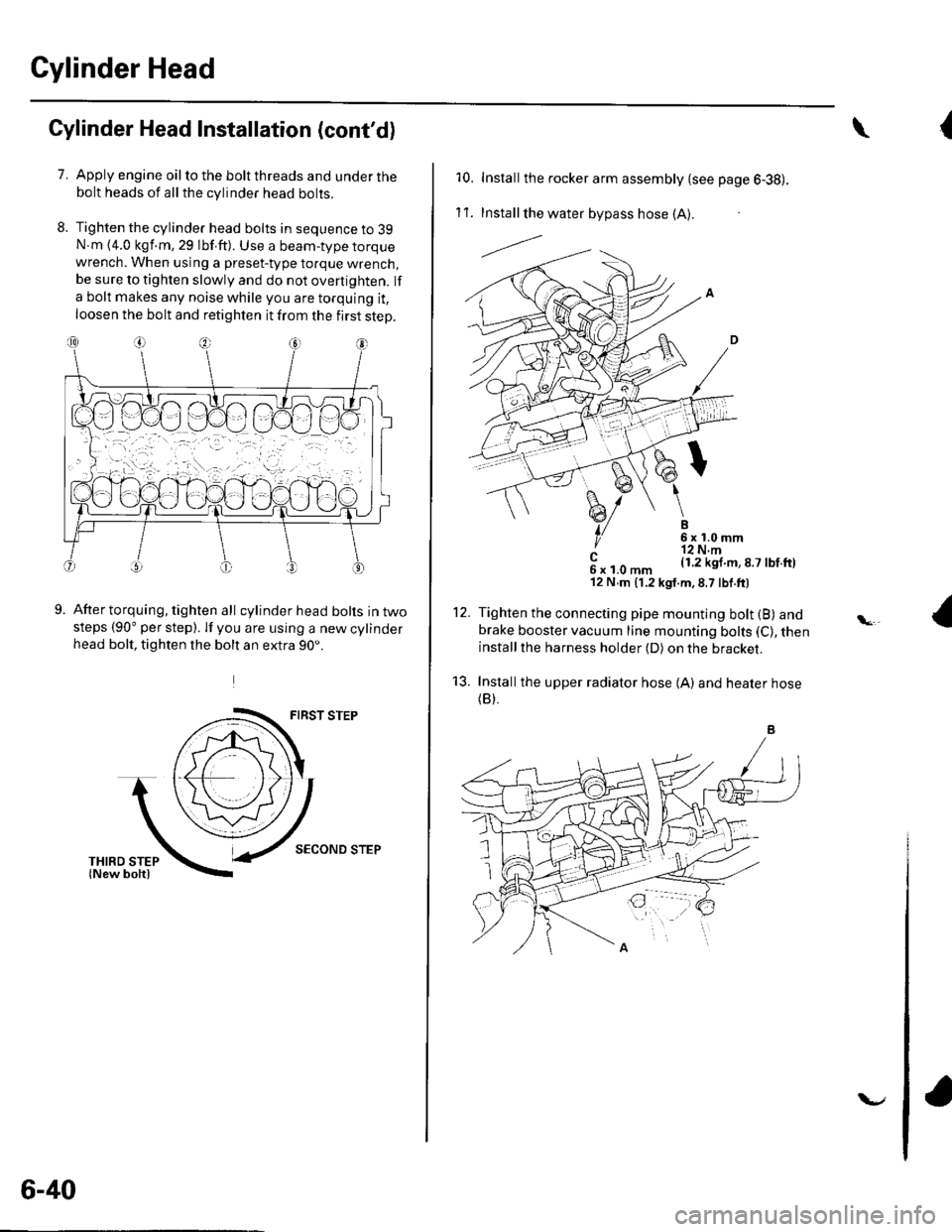
Tighten the cylinder head bolts in sequence to 39N.m {4.0 kgf.m, 29 lbf.ft). Use a beam-type torquewrench. When using a preset-type torque wrench,be sure to tighten slowly and do not overtighten. lf
a bolt makes any noise while you are torquing it,
loosen the bolt and retighten it from the first step.
9.After torquing, tighten all cylinder head bolts in twosteps (90" per step). lf you are using a new cylinderhead bolt, tighten the bolt an extra 90..
FIRST STEP
SECOND STEP
6-40
v
{\
10. Installthe rocker arm assembly {see page 6-38).
1't .Install the water bypass hose (A).
---l.-.
B6x1.0mm'r2 N.m(1.2 kgl.m,8.7 lbf.ftl
12.
't3.
c6xl.0mm'12 N,m (1.2 kgt.m,8.7 lbf.ft)
Tighten the connecting pipe mounting bolt (B) andbrake booster vacuum line mounting bolts (C), theninstallthe harness holder (D) on the bracket.
Installthe upper radiator hose {A) and heater hose(B).
Page 186 of 1139
Intake Manifold and Exhaust System
Intake Manifold Removal and Installation (cont'dl
5. Be prepared to catch and clean up spilled coolant.
Remove the water bypass hoses, then plug the
water bypass hoses.
6. Relievefuel pressure (see page 11-'144).
7. Remove the fuel line (seepagell-149).
8. Remove the positive crankcase ventilation (PCV)
hose (A), harness holder mounting bolt (B) and
harness clamp mounting bolt (C).
9-4
\-
(
9.Remove the engine wire harness connectors and
wire harness clamps from the intake manifold.
. Four injector connectors. ldle air control (lAC) valve connector. Throttle position (TP) sensor connector. fvlanifold absolute pressure {lvlAP) sensor
connector. Evaporative emission (EVAP)canister purge
valve connector
Remove the bolt securing the intake manifold and
bracket.
'1 0.
11.Remove allthe intake manifold mounting bolts/
nuts.
Remove the two stud bolts (A), then remove the
intake manifold (B).
1'>
Page 187 of 1139
1. Install the intake manifold (A)with a new gasket (B),
then install and tighten the two stud bolts (C).
8 x 1.25 mm22 N.m|.2.2k91.m.16 tbt.ft)
8 x 1.25 mm22 N.rn(2.2 kgf m. 16 lbf.ttl
Tighten all intake manifold mountlng bolts/nuts in a
crisscross pattern in two or three steps, beginning
with the inner bolt.
Tighten the bolt securing the intake manifold and
bracket.
8 x 1.25 mm22 N.m (2.2 ksf m, 16lbf.ft)
*&
\
2.
?
w
4.
7.
5.
6.
Install the PCV hose {A), harness holder mounting
bolt (B), and harness clamp mounting bolt (C).
e-li*h,r
6x1.0mm12 N.m (1.2 kgf.m,8.7 lbf.ft)
Installthe fuel line (see page 11-150).
Installthe water bypass hoses.
Install the th rottle cable (see page 1 1-164), then
adjust the cable (see page 11-163).
Install the cruise control cable (see page 4-44). then
adjust the cable (see page 4-45).
8.
(cont'd)
9-5
Page 318 of 1139
Injector Replacement
Relieve fuel pressure (see page 1 l-144).
Disconnect the connectors from the injectors (A), disconnect the ground cable (B), and remove the bracket (C).
(2.2 kgf.m, l6 lbf.ftl
ffi \*\
3. Disconnect the quick-connect fittings (D).
4. Removethefuel rail mountingnuts(E) fromthefuel rail (F)then removethefuel rail and injectors asan assembly.
5. Remove the injector clip (G)from the injector.
6. Remove the injector from the fuel rail.
(cont'd)
11-111
1.
2.
o
Page 319 of 1139
PGM-FI System
Injector Replacement (cont'd)
7. Coatthenewo-rings(A)withcleanengineoll,andinserttheinjectors(B) intothefuel rail (C).
8, lnstall the injector clip {D).
9. Coat the injector o-rings (E)with clean engine oil.
10. Installthe injectors intothefuel rail, then install the fuel rail intotheintakemanifold(G).
1 '1. Install the fuel rail mounting nuts, ground cable. and bracket.
12. Connect the connectors to the injectors.
13. Connect the quick-connect fittings.
14. Turnthe ignition switch ON (ll), butdo notoperatethe starter. Afterthefuel pump runs for about 2 seconds, the
fuel pressure in the fuel line rises. Repeat this two or three times. then check for fuel leakage.
\
11-112
Page 402 of 1139

Clutch Master Cylinder Replacement
NOTE: Do not spill brake fluid on the vehicle; it may
damage the paint; if brake fluid does contact the paint,
wash it off immediatelV with water.
1. Pry out the lock pin (A), and pullthe pedal pin (B)
out of the yoke. Remove the master cylinder
mounting nuts (C).
Remove the air cleaner housing cover and the air
cleaner housing (see step 6 on page 5-2).
Remove the brake fluid from the clutch master
cylinder reservoir with a syringe.
Remove the clutch line bracket from the frame rail,
and remove the clutch line clip.
Remove the clutch master cylinder (A), and pull it
toward the middle of the engine compartment.
Remove the retaining clip (B). Disconnect the clutch
line (C). Plug the end of the clutch line with a shop
towelto prevent brake fluid from coming out.
g-E
3.
6. Disconnect the reservoir hose (D) fromtheclutch
master cylinder reservoir. Plug the end of the
reservoir hose with a shop towel to prevent brake
fluid from coming out.
7. Remove the O-ring (E) and the clutch master
cylinder seal (F) from the master cylinder.
8. Installthe clutch master cylinder in the reverse
order of removal. Install a new O-ring.
9. Make sure the hose clamps (A) are positioned on
the master cylinder (B) and reservoir (C) as shown.
(cont'd)
UP
i
12-5
Page 404 of 1139

Slave Cylinder Replacement
NOTE:. Use fender covers to avoid damaging painted
surfaces.. Do not spill brake fluid on the vehicle; it may damage
the paint; if brake fluid does contact the paint, wash it
off immediately with water.
1. Write down the frequencies for the radio's preset
buttons. Disconnect the negative ( ) cable first,
then the positive (+)cable from the battery.
Remove the battery.
2. Remove the battery tray.
a
Remove the air cleaner housing cover and the air
cleaner housing (see step 6 on page 5-2).
Remove the intake air duct (see step 8 on page 5-3) .
Remove the clutch line bracket (A).
4.
5.
6. Remove the mounting bolts (A) andtheslave
cylinder (B).
Remove the roll pins (C). Disconnect the clutch line(D), and remove the O-ring (E). Plug the end of the
clutch line with a shop towel to prevent brake fluid
f rom coming out.
Installthe slave cylinder in the reverse order of
removal. Install a new O-ring (A).
7.
,,6NJ'
=--#.q!4sEn(P/N 08798-90021
9.
(Brak6 Assembly Lube)
Pullthe boot (B) back, and apply brake assembly
lube to the boot and slave cylinder rod (C). Reinstall
the boot.
Apply super high temp urea grease (P/N 08798-
9002) to the push rod of the slave cylinder. Tighten
the slave cylinder mounting bolts to 22 N m (2.2
kgf m, 16lbf.ft).
(cont'd)
12-7
10.