Page 239 of 1139
Fuel and Emissions Systems
(
{
System Descriptions (cont'd)
ldle Control System
When the engine is cold, the Ay'C compressor is on, the
transmission is in gear, the brake pedal is pressed. thepower steering load is high, or the alternator is
charging, the ECIM controls current to the ldle Air
Control (lAC) valve to maintain the correct idle speed.
Refer to the System Diagram to see the functional
layout of the system.
Brake Pedal Position Switch
The brake pedal position switch signals the ECM when
the brake pedal is oressed.
Electrical Power Steering (EPS) Senser
The EPS sensor signals the ECM when the power
steering load is high.
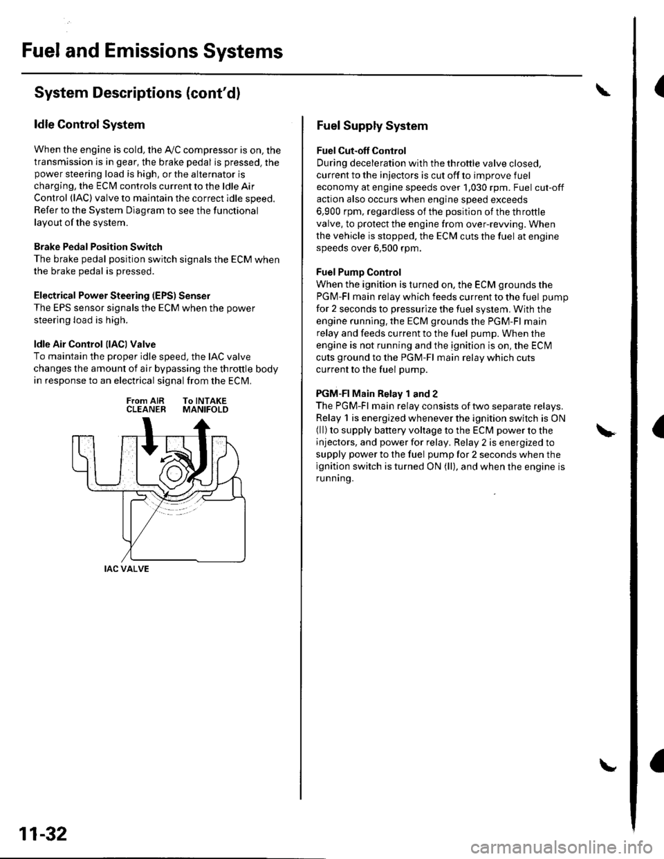
ldle Air Control llACl Valve
To maintain the proper idle speed, the IAC valve
changes the amount of air bypassing the throttle body
in response to an electrical signal from the ECM.
From AIR To INTAKECLEANER MANIFOLD
IAC VALVE
11-32
Fuel Supply System
Fuel Cut-off Control
During deceleration with the throttle valve closed,
current to the injectors is cut off to improve fuel
economy at engine speeds over 1,030 rpm. Fuel cut-off
action also occurs when engine speed exceeds
6,900 rpm, regardless of the position of the throttle
valve, to protect the engine from over-rewing. When
the vehicle is stopped. the ECM cuts the fuel at engine
speeds over 6,500 rpm.
Fuel Pump Control
When the ignition is turned on, the ECM grounds the
PGM-Fl main relay which feeds current to the fuel pump
for 2 seconds to pressurize the fuel system, With the
engine running. the ECM grounds the PGM-Fl main
relay and feeds current to the fuel pump. When the
engine is not running and the ignition is on, the ECI\4
cuts ground to the PGM-Fl main relay which cuts
current to the fuel pump.
PGM-FI Main Relay 1 and 2
The PGM-Fl main relay consists of two separate relays.
Relay 1 is energized whenever the ignition switch is ON(ll) to supply battery voltage to the ECM power to the
injectors, and power for relay, Relay 2 is energized to
supply power to the fuel pump for 2 seconds when the
ignition switch is turned ON (ll), and when the engine is
runnrng.
Page 242 of 1139
Evaporative Emission (EVAPI Control
System
Refer to the System Diagram to see the functional
layout of the system.
EVAP Canister
The EVAP canister temporarily stores fuel vapor from
the fuel tank until it can be purged back into the engine
and burned.
EVAP Canister Purge Valve
When the engine coolant temperatu re is below 149'F(65'C), the ECM turns off the EVAP canister purge valve
which cuts vacuum to the EVAP canister.
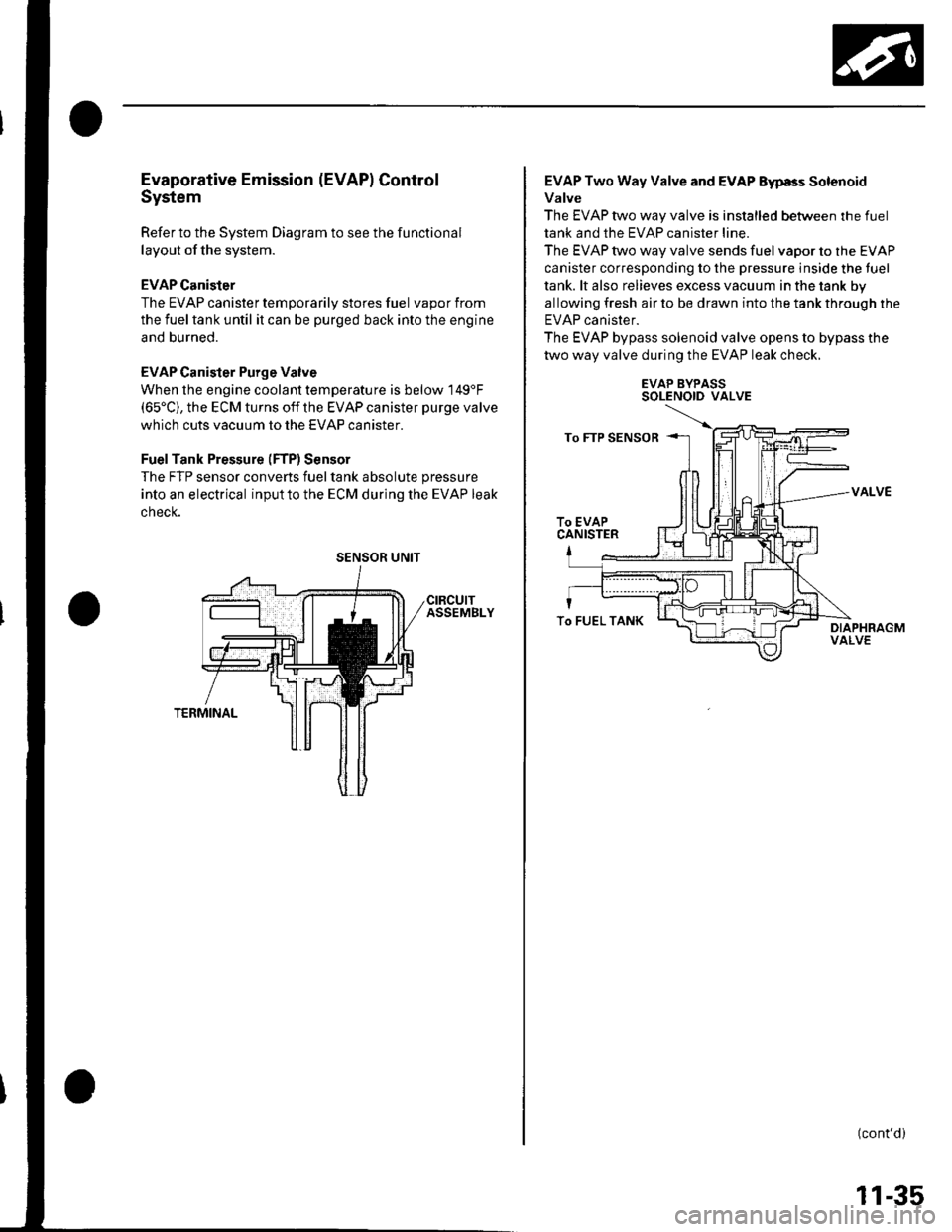
FuelTank Pressure (FTP) Sensor
The FTP sensor converts fueltank absolute pressure
into an electrical inputto the ECM during the EVAP leak
cnecK.
SENSOR UNIT
EVAP Two Way Valve and EVAP Eyp8s Solenoid
Valve
The EVAP two way valve is installed between the fuel
tank and the EVAP canister line.
The EVAP two way valve sends fuel vapor to the EVAP
canister corresponding to the pressure inside the tuel
tank. lt also relieves excess vacuum in the tank by
allowing fresh air to be drawn into the tank through the
EVAP canister.
The EVAP bypass solenoid valve opens to bypass the
two way valve during the EVAP leak check.
EVAP BYPASSSOLENOID VALVE
VALVE
(cont'd)
To FUEL TANK
11-35
Page 274 of 1139
8.Check the secondary H02S (Sensor 2) output
voltage with the scan tool,
ls there 1.0 V ot mote?
YES-Go to step 9.
NO Replace the secondary HO2S (Sensor 2).1
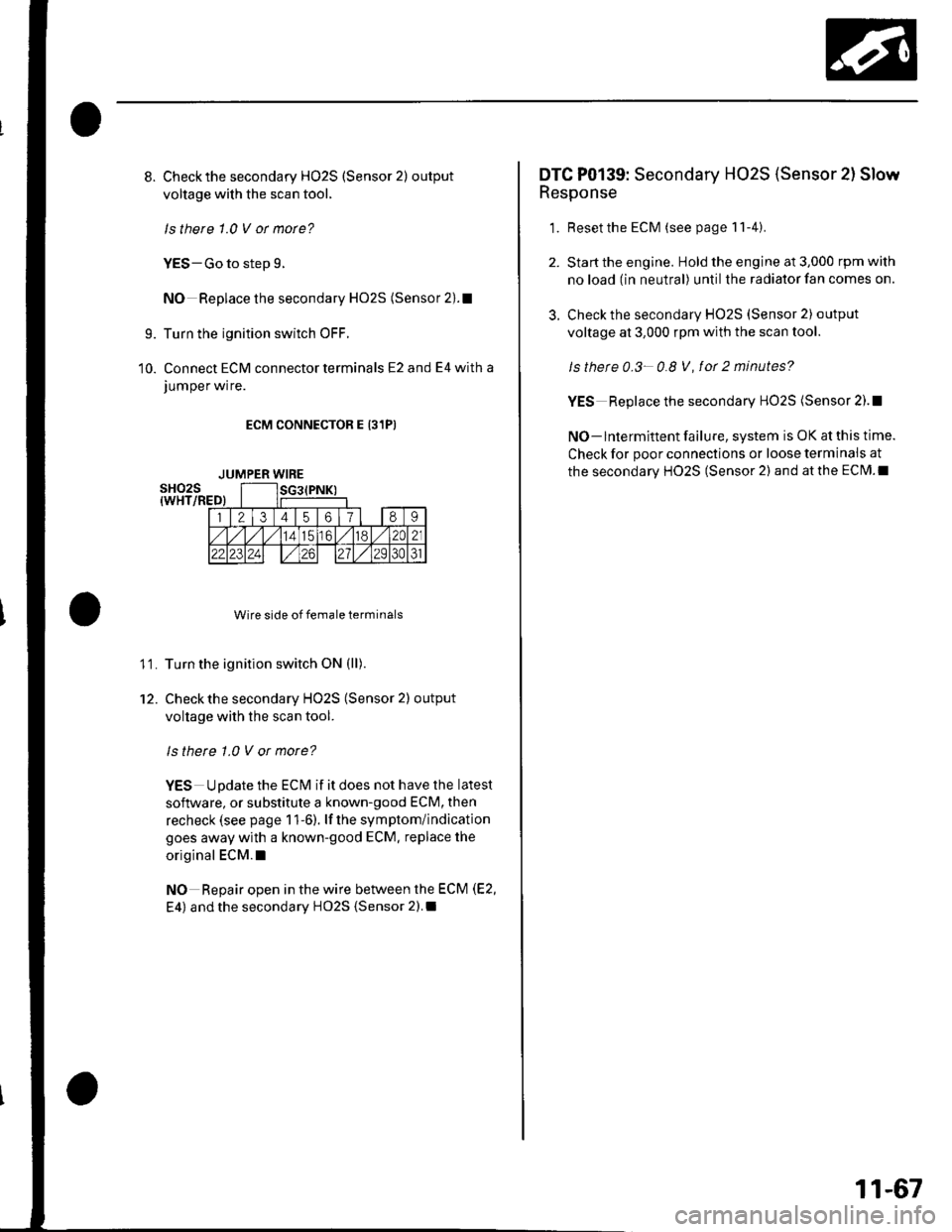
Turn the ignition switch OFF.
Connect ECM connector terminals E2 and E4 with a
JUmper wrre.
ECM CONNECTOR E 131PI
Wire side of female terminals
Turn the ignition switch ON (ll).
Check the secondary HO2S (Sensor 2) output
voltage with the scan tool.
ls there 1.0 V or more?
YES Update the ECM if it does not have the latest
soflware, or substitute a known-good ECM, then
recheck (see page 1 1-6). lf the symptom/indication
goes away with a known-good ECM. replace the
original ECM.I
NO Repair open in the wire between the ECM (E2,
E4) and the secondary HO2S {Sensor 2).I
9.
10.
11.
12.
JUMPER WIRE
3.
DTC P0139: Secondary HO2S (Sensor 2l Slow
Response
1. Resetthe ECM (see page 11-4).
Start the engine. Hold the engine at 3,000 rpm with
no load (in neutral) until the radiator fan comes on.
Check the secondary HO2S (Sensor 2) output
voltage at 3,000 rpm with the scan tool.
ls thete 0.3- 0.8 V, fot 2 minutes?
YES Replace the secondary HO2S (Sensor 2).!
NO- lntermittent failure, system is OK at this time.
Check for poor connections or loose terminais at
the secondary HO2S (Sensor 2) and at the ECM.I
11-67
Page 295 of 1139
PGM-FI System
DTC Troubleshooting (cont'dl
DTC Pl163: Ay'F Sensor (Sensor 1 ) SlowResponse
NOTE: lf DTC P1162 is stored at the same time as DTC
P1163. troubleshoot DTC P1162 first, then recheckfor
DTC P1163.
1. Reset the ECM (see page 1 1-4).
2. Start the engine. Hold the engine at 3,000 rpm with
no load (in neutral) until the radiator fan comes on.
3. Test-drive under the following conditions:
. 55 mph (89 km/h) steady speed' Transmission in sth gear' Until the Ay'F sensor readiness code or
Temporary DTC Pl163 comes on
4. Check for a Temporary DTC with the scan tool.
ls Temporary DTC P 1163 indicated?
YES Replace the Ay'F sensor (Sensor 1).I
NO Intermittent failu re, system is OK at this time.
Check for poor connections or loose terminals at
the A'lF sensor (Sensor 1 ) and at the ECM. t
11-88
DTC Pl164: A,/F Sensor (Sensor 1) Circuit
Range/Performance Problem
1. Resetthe ECI\4 (see page 1t-4).
2. Start the engine. Holdtheengineat3,000 rpmwith
no load (in neutral) until the radiator fan comes on,
3. Test-drive in 3rd gear. Starting at 1,600 rpm,
accelerate using wide open throttle for at least
5 seconds. Then decelerate for at least 5 seconds
with the throttle completely closed until the A,/F
sensor readiness code is set to complete or
Temporary DTC P1 164 comes on.
4. Check for a Temporary DTC with the scan tool.
ls Temporary DTC P1164 indicated?
YES- Replace the A,,/F sensor (Sensor 1). I
NO Intermittent failure, system is OK at this time.
Check for poor connections or loose terminals at
the Ay'F sensor relay, at the Ay'F sensor (Sensor 1),
and at the EcM.l
Page 409 of 1139
Glutch
Clutch Replacement (cont'dl
Clutch Disc and Pressure Plate Installation
'L Temporarily install theclutch disc ontothesplines
of the transmission mainshaft, Make sure the clutch
disc slides freely on the mainshaft.
2. lnstallthe ring gear holder.
{P/N 08798-9002)
07LAB-PVo0'100 or0792,1-PD20003
Apply super high temp urea grease (P/N 08798-
9002) to lhe splines (A) of the clutch disc (B), then
install the clutch disc using the special tools.
Installthe pressure plate (A) and the mounting
bolts (B) finger-tig ht.
\---,
/v
07936-3710100
3.
O?ZAF.PRSAIOO
12-12
5. Torque the mounting bolts in a crisscross pattern,
Tighten the bolts in several steps to prevent
warping the diaphragm spring.
PRESSURE PLATE MOUNTING BOLT TOROUE:
25 N.m {2.6 kgt.m, 19 lbt.ft)
o
Remove the special tools.
Make sure the diaphragm spring fingers are all the
same height.
1.
Page 576 of 1139
Front Suspension
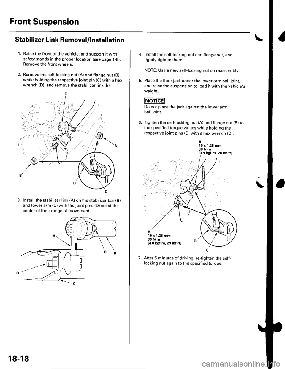
Stabilizer Link Removal/lnstallation
1.Raise the front of the vehicle, and support it with
safety stands in the proper location (see page 1-8).
Remove the front wheels.
Remove the self-locking nut (A) and flange nut {B)while holding the respective joint pin (C) with a hex
wrench (D), and remove the stabilizer link (E).
3. lnstallthe stabilizer link (A) on the stabilizer bar {B)
and lower arm (C) with the joint pins (D) set at the
center of their range of movement.
18-18
4. Install the self-locking nut and flange nut, and
lightly tighten them.
NOTE: Use a new self-locking nut on reassembly.
5. Place the floor jack under the lower arm balljoint,
and raise the suspension to load it with the vehicle's
weaght.
mri-dEl
Do not place the jack against the lower arm
balljoint.
6. Tighten the self-locking nut (A) and flange nut (B) to
the specified torque values while holding the
respective joint pins (C) with a hex wrench (D).
A10 x 1.25 mm38 N.m(3.9 kgf m,28 lbf.ft)
\
..,
1.
B10 x 1.25 mm39 N.m{4.0 kgf.m, 29lbf.ft}
After 5 minutes of driving, re-tighten the self,
locking nut again to the specified torque.
Page 588 of 1139
Rear Suspension
1.
Stabilizer Bar Replacement
Raise the rear of the vehicle, and support it with
safety stands in the proper location (see page 1-8).
Remove the rear wheels.
Remove the self-locking nuts (A) while holding thejoint pins (B) with a hex wrench (C), and disconnect
the stabilizer links (D) from the stabilizer bar {E) on
the right and left.
A10 x 1.25 mm38 N.m(3.9 kgf.m,28 lbf.ft)
Remove the flange bolts (A) and bushing holders(B), then remove the bushings {C) and the stabilizer
bar (D).
18-30
4. Inslallthe stabilizer bar in the reverse order of
removal, and note these items:
. Use new self-locking nuts on reassembly.. lMake sure the right and left ends of the stabilizer
bar are installed on their respective sides of the
vehicle.. Align the ends of the paint marks (A) on the
stabilizer bar with the bushings (B).
. Refer to Stabilizer Link ReDlacement to connect
the stabilizer bar to the links {see page 18-31).
Al\.... '..: .
.----'';-r'--\---r-
-tt'.,'t),
(
Page 589 of 1139
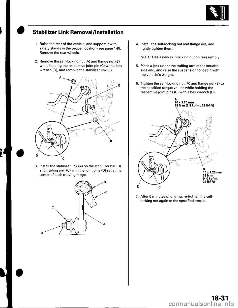
Stabilizer Link Removal/lnstallation
1. Raise the rear of the vehicle, and support it with
safety stands in the proper location (see page 1-8).
Remove the rear wheels.
2. Remove the self-locking nut (A) and flange nut (B)
while holding the respective joint pin {C) wilh a hex
wrench (D), and remove the stabilizer link (E).
3. Installthe stabilizer link (A) on the stabilizer bar {B)
and trailing arm (C) with the joint pins (D) set at the
center of each moving range,
4. lnstall the self-locking nut and flange nut, and
lightly tighten them.
NOTE: Use a new self-locking nut on reassembly.
Place a jack under the trailing arm at the knuckle
side end. and raise the suspension lo load it with
the vehicle's weight.
Tighten the selflocking nut (A) and flange nut {B)to
the specified torque values while holding the
respective joint pins (C) with a hex wrench (D).
A10 x 1.25 mm38 N.m 13.9 kgf.m,28lbf.ftl
7. After 5 minutes of driving, re-tighten the self-
locking nut again to the specified torque.
\,1 i
i'-r d
*l'',:
18-31