Page 993 of 1139
lmmobilizer System
Component Location Index
INOICATOR LIGHTBulb Replacement, page 22 63ECMReplacement, page 11-4Substitute known-good for testing,page 11-5
IMMOBILIZER CONTROL UNIT.RECEIVERTroubleshooting, page 22-165Replacement, page 22-167
TRANSPONDER(8uilt into the ignition key)
22-162
Page 994 of 1139

System Description
The vehicle is equipped with an immobilizer system that will disable the vehicle unless the proper ignition key is used.This system consists of a transponder located in the ignition key, an immobilizer control unit-receiver, an indicatorlight, and the ECM.
When the key is inserted in the ignition switch and turned to the ON {ll) position, the immobilizer control unit-receiversends power to the transponder in the ignition key. The transponder then sends a coded signal back to the immobilizer
control unit-receiver which then sends a coded signal to the ECI\4.
iEl'JUiliii'tlun"oona"|.r KEYCYLTNDER
lf the proper key has been used, the immobilizer indicator light will come on for about 2 seconds, then go off.lf the wrong key has been used or the code was not received or recognized by the unit, the indicator light will comeon for about 2 seconds, then it will blink until the ignition switch is turned OFF.lf the ignition switch is turned OFF, the indicator will blink for about 5 seconds to signal that the unit has reset
correctly, then the indicator will go off.
lf the customer has lost his key, and cannot start the engine, contact Honda Customer Relations.
IMMOBILIZER INDICATOR LIGHT BLINKING PATTERN:
IGNITION SWITCHON
OFF
PROPER KEYINSERTEDINDICATORLIGHTON
WRONG KEYINSERTEDINDICATORLIGHTON
OFF
(| i.,
IMMOBILIZER CONTROL UNIT.RECEIVER
)
22-163
Page 996 of 1139

)
I
Troubleshooting
Before troubleshooting the immobilizer system,
troubleshoot any EClvl Diagnostic Trouble Codes (DTCS)
(see page 11-3), and make sure the ECM has no
malfunction.
Note these items before trou bleshooting:
. Due to the action of the immobilizer system, the
engine takes slightly more time to start than on a
vehicle without an immobilizer system.. When the system is normal, and the proper key is
inserted, the indicator light comes on for 2 seconds,
then it will go off.. If the indicatorstartsto blink after 2 seconds, or if the
engine does not start. remove any other immobilizer
keys or large key fobs on the key ring, then repeat the
starting procedure.
lf the engine still does not start, continue with thisprocedure.
1. Turn the ignition switch ON {ll) with proper key.
2. Check to see if the immobilizer indicator light
comes on.
Does the indicator light blink?
YES Disconnect the 7P connector from the
immobilizer control unit-receiver, then go to step 9.
NO Check for these problems, then go to step 3.
. Blown No. 9 (10A)fuse in the under-hood
fuse/relay box.I. An open in the wire between the gauge assembly
and the immobilizer control unit-receiver.l. A faulty immobilizer indicator light,I. An open in the wire between the gauge assembly
and the under-hood fuse/relay box.l
Remove the driver's dashboard lower cover (see
page 20-59).
Remove the steering column lower cover (see page
11-9).
l
-_--t
22-165
5. Disconnect the 7P connector (A)from the
immobilizer control unit-receiver (B),
Check for voltage between the immobilizer control
unit-receiver 7P connector No. 7 terminal and body
ground.
ls there battery voltage?
YES-Go to step 7.
NO Check for these problems;
. Blown No. 9 {10A)fuse in the under-hood fuse/
relay box.l. An open in the WHT/RED wire.l
Check for voltage between the immobilizer control
unit-receiver 7P connector No. 6 terminal and bodyground with the ignition switch ON {ll).
ls there battery voltage?
YES- Go to step 8.
NO Check for these problems:
. Blown No.6 (15A)fuse in the under-hood
fuse/relay box,I. Faulty PGM-Fl main relay 1,t. An open in the YEUBLK wire.l
1.
(cont'd)
Page 999 of 1139
Multiplex Control System
Component Location Index
IGNITION KEY LIGHTTest, page 22'91
lr, J
REAR CEILING LIGHTTest, page 22'96
LIGHT/SPOTLIGHTSTest, page 22-96
GAUGE ASSEMBLY
ECM
MULTIPLEX CONTROL UNIT{Built into the under-dashfus6/relav boxlTroubleshooting, page 22'172Input Test, page 22-175
22-168
t
Page 1001 of 1139
Multiplex Control System
J
J
Circuit Diagram (cont'd)
l'1o.3 l7.5AJ tUStlln$.uidt hoodritutefd4bor I
V
IwHTPLU
l0t--t---
lrfl |
lE lnv*-| > | ucHT
lA l'*'tYl
I'
CIILING LIGHT
I.l|MOBItEER@NTIOL UIIITRECEIVEE
VI
I
22-170
{
Page 1002 of 1139

ISystem Descriptions
The Multiplex Control System has four internal
functions:. Multiplexing (send multiple signals over sharedwtres). Wake up/sleep (runs at full power only on demand toreduce battery draw). Fail-safe (fixes or ignores faulty signals). Self-diagnosis (Mode 1 for the system, Mode 2 for
input lines)
The system controls the function of these circuits:. Entry lightcontrol (ignition key lightandceiting light). Wiper/washer intermittent wipe and park functions. Keyless/power door lock. Meter assembly, temperature gauge, and indicator
lights. HVAC (compressor and fan control). Key-in reminder. Headlight reminder. Seatbelt reminder
JI
/ar
22-171
Multiplex Communication
To reduce the number of wire harnesses, digital signals
are sent via shared multiplex communication linesrather than sending normal electrical signals throughindividual wires.. The input signals from each switch are converted todigital signals at the central processing unit (CpU).. The digital signalsaresentfromthetransmitting unitto the receiving unit as serial signals.. The transmitted signal is converted to a switch signalat the receiving unit, and it operates the related
component or monitors a swltch.. There are exclusive communicalion lines between
the ECM, the gauge assembly, and the under,dash
fuse/relay box.
Wake-up and Sleep
The multiplex control system has "wake-up" and"sleep" functions to decrease parasitic draw on the
battery when the ignition switch is OFF.. ln the sleep mode, the multiplex control unit stops
functioning (communication and CPU control) when it
is not necessary for the system to operate.. As soon as any operation is requested (for example, adoor is unlocked), the related control unit in the sleep
mode immediately wakes up and begins to function.. When the ignition switch is turned OFF, and the
driver's or front passenger's door is opened, then
closed, there is about a 10 second delay before the
control unit goes from the wake-up mode to the sleepmode.. lf any door is open, the sleep mode will not function.. lf a key is in the ignition switch, the sleep mode will
not function.. When in sleep mode, the draw is reduced from
70 80 mA to less than 10 mA.
Fail-safe
To prevent improper operation, the multiplex controlsystem has a fail-safe function. In the fail-safe mode,
the output signal js fixed when any part of the systemmalfunctions (for example a faulty control unit orcommunication line).
Each control unit has a hardware fail-safe function thatfixes the output signal when there is any CPUmalfunction, and a software fail-safe function thatignores the signal from the malfunctioning control unitand allows the system to operate normally.
Page 1003 of 1139

Multiplex Control System
Troubleshooting
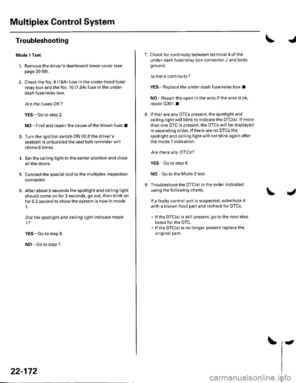
Mode 1 Tset
1. Remove the driver's dashboard lower cover {see
page 20-59).
2. Check the No. 9 ( 10A) fuse in the under-hood fuse/
relay box and the No. 10 (7.5A) fuse in the under-
dash fuse/relay box.
Are the fuses OK?
YES-Go to step 2.
NO-Find and repairthe cause ofthe blown fuse.!
3. Turn the ignition switch ON (ll).lf the driver's
seatbelt is unbuckled the seat belt reminder will
chime 6 times.
4. Set the ceiling light to the center position and close
allthe doors.
5. Connect the specialtoolto the multiplex inspection
conneclor.
6. After about 5 seconds the spotlight and ceiling light
should come on for 2 seconds, go out, then blink on
for 0.2 second to show the system is now in mode
1.
Did the spotlight and ceiling light indicate mode
1?
YES-Go to step 8.
NO Go to step 7.
22-172
-
7. Check for continuity between terminal 4ofthe
under-dash fuse/relay box connector J and body
ground.
ls there continuity?
YES Replace the under-dash fuse/relay box.l
NO - Repair the open in the wire.lf the wire is ok,
repair G301.1
8. lf ther are any DTCS present, the spotlight and
ceiling light will blink to indicate the DTC(S). lf more
than one DTC is present, the DTCS will be displayed
in ascending order, lf there are no DTCS the
spotlight and ceiling light will not blink again after
the mode 1 indication.
Are there any DTCg?
YES Go to step 9.
NO Go to the Mode 2 test.
9. Troubleshoot the DTC(S) in the order indicated
using the following charts.
lf a faulty control unit is suspected, substitute it
with a known food part and recheck for DTCS,
. lf the DTC(s) isstill present. go to the next step
listed for the DTC.. lf the DTC(S) is no longer present replace the
original part.
Page 1008 of 1139

IJ
IJ
IJ
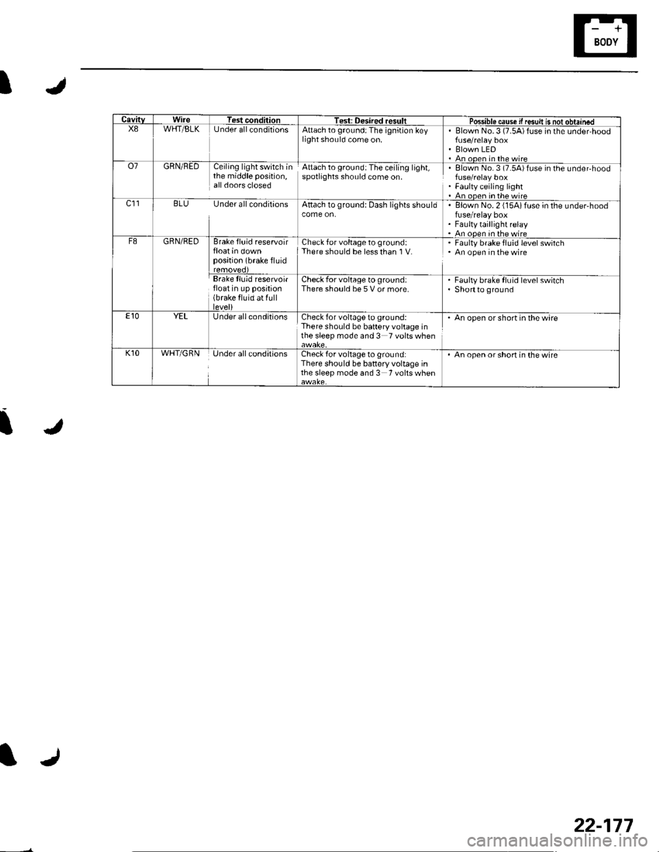
CavitvWireTest conditionTest: Desired resultPossible cause if resuk is not obtainedX8WHT/BLKUnder allconditionsAttach to ground:The ignition keylight should come on.Blown No.3 (7.5A)fuse in the under,hood
Blown LEDAn ooen in the wireo7GRN/REDCeiling light switch inthe middle position,all doors closed
Attach to ground:The ceiling light,spotlights should come on.Elown No. 3 (7.54)fuse in the undeFhood
Faulty ceiling lightAn oDen in the wirec]1BLU Under all conditionsAttach to ground: Dash lights shouldBlown No. 2 (15Aifuse in the under-hoodfuse/relay boxFaulty taillight relayAn ooen in the wireF8GRN/REDBrake fluid reservoirfloat in downposition (brake fluid
Check for voltage to ground:There should be less than I V.Faulty brake fluid level switchAn open in the wire
Brake lluid reservoirfloat in up position(brake fluid at fulllevel)
Check for voltage to ground:There should be 5 V or more.Faulty brake fluid level switchShortto ground
E10YELUnder all conditionsCheck for voltage to ground:There should be battery voltage inthe sleep mode and 3 Tvoltswhen
. An open or short in the wire
K10WHT/GRNUnder all conditionsCheck for voltage to ground:There should be battery voltage inthe sleep mode and 3 Tvoltswhen
An open or short in the wire
22-177