Page 3 of 264
Maintenance and Specifications 201
Hood 203
Engine compartment 204
Engine oil 206
Battery 210
Fuel information 221
Part numbers 246
Refill capacities 247
Lubricant specifications 249
Engine data 251
Vehicle dimensions 251
Accessories 254
Index 258
All rights reserved. Reproduction by any means, electronic
or mechanical including photocopying, recording or by any
information storage and retrieval system or translation in
whole or part is not permitted without written
authorization from Ford Motor Company. Ford may change
the contents without notice and without incurring
obligation.
Copyright 2001 Ford Motor Company
Table of Contents
3
Page 7 of 264
Notice to owners of Cobra vehicles
Before you drive your vehicle, be sure to read the
ªSVT Cobra Owner's Guide Supplement.º This book
contains important operation and maintenance
information.
MIDDLE EAST/NORTH AFRICA VEHICLE
SPECIFIC INFORMATION
For your particular global region, your vehicle may
be equipped with features and options that are
different from the ones that are described in this
Owner Guide; therefore, a supplement has been
supplied that complements this book. By referring to
the pages in the provided supplement, you can
properly identify those features, recommendations
and specifications that are unique to your vehicle.
Refer to this Owner Guide for all other
required information and warnings.
Introduction
7
Page 13 of 264

Check fuel cap
Illuminates when the
fuel cap is not installed
correctly. Check the
fuel cap for proper
installation. When the fuel filler cap is properly
re-installed, the light(s) will turn off after a period of
normal driving. Continuing to operate the vehicle
with the check fuel cap light on, can activate the
Service Engine Soon/Check Enginewarning light.
It may take a long period of time for the
system to detect an improperly installed fuel
filler cap.
For more information, refer toFuel filler capin the
Maintenance and specificationschapter.
Low fuel
Illuminates when the
fuel level in the fuel
tank is at, or near,
empty (refer toFuel
gaugein this chapter for more information).
O/D off (if equipped)
Illuminates when the
overdrive function has
been turned OFF using
the Transmission Control Switch (TCS) on the
gearshift. If the light does not come on or the light
flashes steadily, have your vehicle serviced as soon
as possible, damage to the transmission could occur.
CHECK
FUEL
CAP
LOW
FUEL
O/D
OFF
Instrument Cluster
13
Page 16 of 264
GAUGES
Base instrument cluster gauges
Optional instrument cluster gauges
Engine coolant temperature gauge
Indicates the
temperature of the
engine coolant. At
normal operating
temperature, the needle remains within the normal
area (the area between the ªHº and ªCº). If it enters
the red section, the engine is overheating. Stop the
vehicle as soon as safely possible, switch off the
engine immediately and let the engine cool. Refer to
Engine coolantin theMaintenance and
specificationschapter.
P! BRAKE
L C
EFH
LH
10 203020 406080100
120
140
160
180
405060 70
80
90
100
11 0
1204
5
6
7 3
2
1
H
THEFT
RPMX1000
FUEL DOORSELECT/RESET
LOW
FUELO/D
OFF AIR
BAGSERVICE
ENGINE
SOON
MPH km/h
ABS
00000 00.
CHECK
FUEL
CAP
P! BRAKE
0
00000 00
FH
H
102040608020 40608010 012 0 14 0
160
180
200
220
240
100
120
140
305070 90
110
13 0
1504
5
6
7
8 3
2
1
H
THEFT
RPMX1000
FUEL DOORSELECT/RESET
LOW
FUELO/D
OFF AIR
BAGSERVICE
ENGINE
SOON
MPH km/h
ABS
.
L
LCHECK
FUEL
CAP
CH
Instrument Cluster
16
Page 17 of 264

Never remove the coolant reservoir cap
while the engine is running or hot. Steam
and scalding liquid from a hot cooling system can
burn you badly.
This gauge indicates the temperature of the engine
coolant, not the coolant level. If the coolant is not at
its proper level the gauge indication will not be
accurate.
Engine oil pressure gauge
Indicates engine oil
pressure. At normal
operating temperature,
the needle will be in
the normal range (the area between the ªLº and
ªHº); if the needle goes below the normal range,
stop the vehicle as soon as safely possible and
switch off the engine immediately. Check the oil
level. Add oil if needed (refer toEngine oilin the
Maintenance and specificationschapter). If the oil
level is correct, have your vehicle checked at your
dealership or by a qualified technician.
Battery voltage gauge
Indicates battery
voltage. If the pointer
moves and stays
outside the normal
operating range (as indicated by the arrows), have
the vehicle's electrical system checked as soon as
possible.
LH
LH
Instrument Cluster
17
Page 119 of 264

Safety belt maintenance
Inspect the safety belt systems periodically to make
sure they work properly and are not damaged.
Inspect the safety belts to make sure there are no
nicks, tears or cuts. Replace if necessary. All safety
belt assemblies, including retractors, buckles, front
seat belt buckle assemblies, buckle support
assemblies (slide bar-if equipped), shoulder belt
height adjusters (if equipped), shoulder belt guide
on seatback (if equipped), child safety seat tether
bracket assemblies (if equipped), LATCH child seat
tether anchors and lower anchors (if equipped), and
attaching hardware, should be inspected after a
collision. Ford Motor Company recommends that all
safety belt assemblies used in vehicles involved in a
collision be replaced. However, if the collision was
minor and a qualified technician finds that the belts
do not show damage and continue to operate
properly, they do not need to be replaced. Safety
belt assemblies not in use during a collision should
also be inspected and replaced if either damage or
improper operation is noted.
Failure to inspect and if necessary replace
the safety belt assembly under the above
conditions could result in severe personal injuries
in the event of a collision.
Refer toCleaning and maintaining the safety
beltsin theCleaningchapter.
Seating and Safety Restraints
119
Page 125 of 264

The diagnostic module monitors its own internal
circuits and the supplemental air bag electrical
system warning (including the impact sensors), the
system wiring, the air bag system readiness light, the
air bag back up power and the air bag ignitors.
Several air bag system components get hot
after inflation. Do not touch them after
inflation.
If the air bag has deployed,the air bag will
not function again and must be replaced
immediately.If the air bag is not replaced, the
unrepaired area will increase the risk of injury in a
collision.
Determining if the system is operational
The SRS uses a readiness light in the instrument
cluster or a tone to indicate the condition of the
system. Refer toAir bag readinesssection in the
Instrument clusterchapter. Routine maintenance of
the air bag is not required.
A difficulty with the system is indicated by one or
more of the following:
²The readiness light
will either flash or
stay lit.
²The readiness light will not illuminate immediately
after ignition is turned on.
²A series of five beeps will be heard. The tone
pattern will repeat periodically until the problem
and/or light are repaired.
If any of these things happen, even intermittently,
have the SRS serviced at your dealership or by a
qualified technician immediately. Unless serviced,
the system may not function properly in the event of
a collision.
AIR
BAG
Seating and Safety Restraints
125
Page 142 of 264

BRAKES
Your service brakes are self-adjusting. Refer to the
scheduled maintenance guide for scheduled
maintenance.
Occasional brake noise is normal and often does not
indicate a performance concern with the vehicle's
brake system. In normal operation, automotive brake
systems may emit occasional or intermittent squeal
or groan noises when the brakes are applied. Such
noises are usually heard during the first few brake
applications in the morning; however, they may be
heard at any time while braking and can be
aggravated by environmental conditions such as
cold, heat, moisture, road dust, salt or mud. If a
ªmetal-to-metal,º ªcontinuous grindingº or
ªcontinuous squealº sound is present while braking,
the brake linings may be worn-out and should be
inspected by a qualified service technician.
If you are driving down a long or steep hill,
shift to a lower gear. Do not apply your
brakes continuously, as they may overheat and
become less effective.
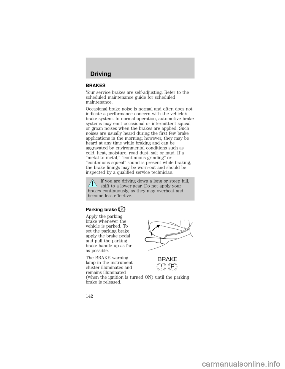
Parking brake
Apply the parking
brake whenever the
vehicle is parked. To
set the parking brake,
apply the brake pedal
and pull the parking
brake handle up as far
as possible.
The BRAKE warning
lamp in the instrument
cluster illuminates and
remains illuminated
(when the ignition is turned ON) until the parking
brake is released.
P!
BRAKE
Driving
142