Page 65 of 256
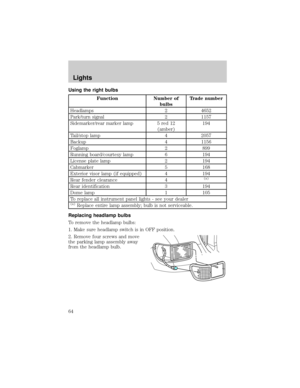
3. Remove four screws and the
retaining bracket from the headlamp
bulb.
4. Pull headlamp bulb out of the
housing, disconnect the electrical
connector and remove the headlamp
bulb.
5. To complete installation, follow
the removal procedure in reverse
order.
Replacing front parking lamp/turn signal bulbs
To remove the parking/turn signal bulbs:
1. Make sure the headlamp control is in the OFF position.
2. Remove four screws from the
lamp assembly.
3. Carefully lower lamp assembly
and pull the bulb socket straight out
of the lamp assembly.
4. Carefully pull the bulb straight
out of the socket and push in the
new bulb.
5. To complete installation, follow
the removal procedure in reverse order.
Lights
65
Page 66 of 256
Replacing visor/cab marker bulbs
To change the cab marker bulbs:
1. Remove the screw and lens from
the lamp assembly.
2. Carefully pull the bulb straight
out of the socket and push in the
new bulb.
3. Install lens on lamp assembly with
screw.
Replacing visor marker bulbs (SuperCrewzer only)
For visor bulb replacement see a dealer or qualified technician.
Replacing brake/tail/backup lamp bulbs ± Except F650
SuperCrewzer
The brake/tail/backup lamp bulbs
are located in the same portion of
the tail lamp assembly. Follow the
same steps to replace either bulb:
1. Remove the four screws and the
lamp lens from lamp assembly.
2. Carefully pull the bulb straight
out of the socket and push in the
new bulb.
3. Install the lens on the lamp
assembly with the four screws.
Lights
66
Page 67 of 256
Replacing tail lamp/turn/backup lamp bulbs Ð F650 SuperCrewzer
only
The tail lamp/backup lamp bulbs are
located in the same portion of the
tail lamp assembly, one just below
the other. Follow the same steps to
replace either bulb:
1. Remove the two screws holding
the light cover to the light housing.
2. Carefully pull away the lamp
cover.
3. Twist the bulb 1/8 of a turn
counter clockwise and remove it
from the socket.
4. Pull the bulb straight out and push the new bulb in.
5. Turn the bulb clockwise to secure in place.
6. Replace the tail lamp cover and secure with the two screws.
Replacing foglamp bulbs (if equipped)
1. Remove the bulb socket from the
foglamp by turning
counterclockwise.
2. Disconnect the electrical
connector from the foglamp bulb.
3. Connect the new foglamp bulb to the electrical connector.
4. Install the bulb socket in the foglamp by turning clockwise.
Lights
67
Page 68 of 256

WINDSHIELD WIPER/WASHER CONTROLS
Rotate the windshield wiper control
to the desired interval, low or high
speed position.
The bars of varying length are for
intermittent wipers. When in this
position rotate the control upward
for fast intervals and downward for
slow intervals.
Push the control on the end of the
stalk to activate washer. Push and
hold for a longer wash cycle. The
washer will automatically shut off
after ten seconds of continuous use.
Windshield wiper blades
Check the wiper blades at least twice a year or when they seem less
effective. Substances such as tree sap and some hot wax treatments used
by commercial car washes reduce the effectiveness of wiper blades.
Checking the wiper blades
If the wiper blades do not wipe properly, clean both the windshield and
wiper blades using undiluted windshield wiper solution or a mild
detergent. Rinse thoroughly with clean water. To avoid damaging the
blades, do not use fuel, kerosene, paint thinner or other solvents.
Driver Controls
68
Page 69 of 256
Changing the wiper blades
To replace the wiper blades:
1. Pull the wiper arm away from the
windshield and lock into the service
position.
2. Turn the blade at an angle from
the wiper arm. Push the lock pin
manually to release the blade and
pull the wiper blade down toward
the windshield to remove it from the
arm.
3. Attach the new wiper to the
wiper arm and press it into place
until a click is heard.
TILT STEERING WHEEL
Pull the tilt steering control toward
you to move the steering wheel up
or down. Hold the control while
adjusting the wheel to the desired
position, then release the control to
lock the steering wheel in position.
Driver Controls
69
Page 70 of 256

Never adjust the steering wheel when the vehicle is moving.
OVERHEAD CONSOLE (IF EQUIPPED)
The overhead console will show the outside temperature and compass
display.
Electronic compass/temperature display Ð SuperCrewzer only
Mode control
Press the MODE control to turn the
display on/off.
Outside air temperature
The outside temperature display is
contained in the overhead console.
The temperature can be displayed in
Centigrade or Fahrenheit by
pressing the E/M control.
If the outside temperature falls
below 3ÉC (38ÉF), the display will
alternate from ªICEº to the outside
temperature at a two second rate
for one minute.
Compass
The compass display is contained in the overhead console. The vehicle
heading is displayed as one of N, NE, E, SE, S, SW, W and NW.
The compass reading may be affected when you drive near large
buildings, bridges, power lines and powerful broadcast antenna. Magnetic
or metallic objects placed in or on the vehicle may also affect compass
RESET MODEE/M
RESET MODEE/M
Driver Controls
70
Page 71 of 256
accuracy. Adjustments may need to be made to the zone and calibration
of the compass.
Usually, when something affects the compass readings, the compass will
correct itself after a few days of operating your vehicle in normal
conditions. If the compass still appears to be inaccurate, a manual
calibration may be necessary. Refer toCompass calibration
adjustment.
Most geographic areas (zones) have a magnetic north compass point that
varies slightly from the northerly direction on maps. This variation is four
degrees between adjacent zones and will become noticeable as the
vehicle crosses multiple zones. A correct zone setting will eliminate this
error. Refer toCompass zone adjustment.
Compass zone adjustment
1. Determine which magnetic zone
you are in for your geographic
location by referring to the zone
map.
2. Locate the controls on the
overhead console.
3. Turn ignition to the ON position.
1
2
3
4
5
6
7891011121314 15
Driver Controls
71
Page 72 of 256

4. Press and hold both controls.
After approximately four seconds,
the compass will enter zone setting
mode. Zone setting mode is
indicated when the display lights the
ªZONEº indicator.
5. Release both controls.
Subsequent pressing of either
control will increment the zone.
Press the control repeatedly until
the correct zone setting for your
geographic location is displayed on the trip computer.
6. To exit the zone setting mode and save the displayed zone in memory,
release both controls for greater than five seconds.
Compass calibration adjustment
Perform this adjustment in an open area free from steel structures and
high voltage lines.
For optimum calibration, turn off all electrical accessories (heater/air
conditioning, wipers, etc.) and make sure all vehicle doors are shut.
1. Locate the controls located in the overhead console.
2. Start the vehicle.
3. Press and hold both controls.
After approximately eight seconds,
the compass will enter CAL mode.
CAL mode is indicated when the
display lights the ªCALº indicator.
4. Release both controls. The display
will return to normal, except that
the CAL indicator will remain lit
until the compass is sucessfully
calibrated.
5. Slowly drive the vehicle in a circle (less than 5 km/h [3 mph]) until
the CAL indicator turns off. It may take up to five circles to complete
calibration.
6. The compass is now calibrated.
RESET MODEE/M
RESET MODEE/M
Driver Controls
72