Page 41 of 320

Starting autoset memory preset
1. Select a frequency using the AM/FM select controls.
2. Press the AUTO control.
3. When the first six strong stations
are filled, the station stored in
memory preset control 1 will start
playing.
If there are less than six strong stations available on the frequency band,
the remaining memory preset controls will all store the last strong
station available.
To deactivate autoset and return to your audio system's manually set
memory stations, press the control again.
Setting the clock with radio data system (RDS) feature
Press the RDS control until SELECT
HOUR or SELECT MINS is
displayed.
Use the SEL control to manually set
the time.
²Press
to increase
hours/minutes.
²Press
to decrease
hours/minutes.
Tune adjust
The tune control works in radio or CD mode (if equipped).
Tune adjust in radio mode
²Pressto move to the next
frequency down the band
(whether or not a listenable
station is located there). Hold the control to move through the
frequencies quickly.
²Press
to move to the next frequency up the band (whether or not
a listenable station is located there). Hold for quick movement.
AUTO
RDS
SEL
TUNE
Entertainment Systems
41
Page 46 of 320
Show
²With RDS activated, press the
RDS control until SHOW is
displayed.
²Use the SEL control to select
TYPE (the display shows the
program type), NAME (the
display shows the call letters of
the station) or NONE.
HARLEY-DAVIDSON REAR SEAT CONTROLS (IF EQUIPPED)
The rear seat controls allow the
middle seat passengers to operate
the radio, tape, CD or CD changer
(if equipped).
To turn on the rear seat controls,
press the memory preset controls 3
and 5 at the same time. The
will appear in the display.
Pressing 3 and 5 at the same time
again will turn the rear seat controls
off.
If there is a discrepancy between the rear seat and the front audio
controls, (such as both trying to listen to the same playing media), the
front audio system will receive the desired selection.
RDS
SEL
- VOLUME +
MODE
SEEK MEMORY
REW1FF2SIDE 1-23
4COMP5SHUFFLE6
Entertainment Systems
46
Page 48 of 320
MODE SELECT
Push the MODE control to toggle
between AM, FM1, FM2, tape, CD or
CD changer (if equipped).
MEMORY PRESET CONTROL
Push the MEMORY control
successively to allow rear seat
passengers to scroll through the 6
memory presets in AM, FM1 or
FM2.
Push the MEMORY control in CD
changer mode (if equipped) to
advance to the next disc.
SEEK FUNCTION
²In radio mode, press
to find
the next listenable station down
the frequency band.
²In radio mode, press
to find
the next listenable station up the
frequency band.
²In tape mode, use the SEEK
function to access the next
or
previous
selection.
²In CD mode (if equipped), use
the SEEK function to access the next
or previousselection.
- VOLUME +
MODE
SEEK MEMORY
- VOLUME +
MODE
SEEK MEMORY
- VOLUME +
MODE
SEEK MEMORY
Entertainment Systems
48
Page 207 of 320

Installing the snowplow
Removing the blocker beam without installing snowplow
attachment hardware may affect air bag deployment in a crash.
Do not operate the truck unless either the blocker beam or snowplow
attachment hardware is installed on the vehicle.
Read the following instructions before installing a snowplow:
²Front GAWR must not exceed 63% of the GVW. Add ballast weight to
the back of the vehicle, if necessary. Refer to the Safety Compliance
Certification Label to find Front GAWR.
²The Front Axle Accessory Reserve Capacity and the Total Accessory
Reserve Capacity listed on the bottom right of the Safety Compliance
Certification Label will determine whether or not the addition of a
snowplow will overload your vehicle.
²The weight of the snowplow and supporting components distributed to
the front axle must not exceed the front accessory reserve capacity.
²The total weight of the snowplow and aftermarket equipment must
not exceed the Total Accessory Reserve Capacity.
²The weight of the installed snowplow and aftermarket equipment must
not load the vehicle beyond the GAWR (front/rear) and GVWR listed
on the Safety Compliance Certification Label.
²The total weight of the snowplow and aftermarket equipment must be
considered part of the payload and must not exceed the Gross
Combined Weight Rating (GCWR) for towing.
²Federal and most local regulations require additional exterior lamps
for snowplow-equipped vehicles. Consult your dealer for additional
information.
²After installing a snowplow to the vehicle, ensure the vehicle's front
toe alignment and front ride height are within specification (reset if
required). These specifications are located in the vehicle's Workshop
Manual. Adherence to the toe, tire pressures and ride height
specification is important for proper tire wear, ride, handling and
headlight aim. Also, maintain the engine oil and transmission fluid
change intervals following the severe duty schedule.
Do not exceed the GVWR or the GAWR specified on the
certification label.
Driving
207
Page 208 of 320

Removing snowplow
Read the following instructions before removing a snowplow:
²After removing a snowplow from the vehicle, ensure the vehicle's front
toe alignment and front ride height are within specification (reset if
required). These specifications are located in the vehicle's Workshop
Manual. Adherence to the toe and ride height specification is
important for proper tire wear, ride, handling and headlight aim.
Snowplowing with your air bag equipped vehicle
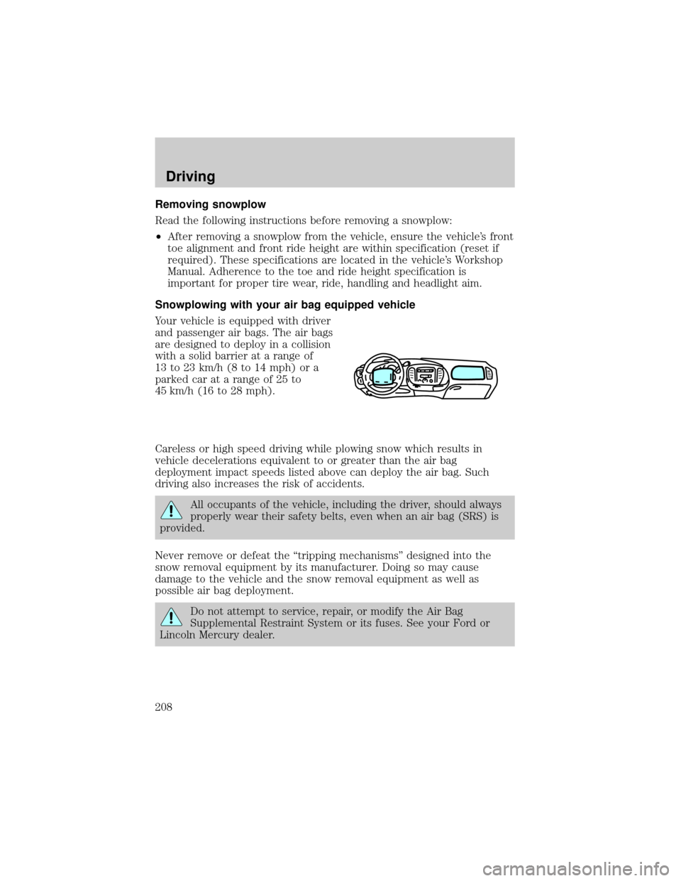
Your vehicle is equipped with driver
and passenger air bags. The air bags
are designed to deploy in a collision
with a solid barrier at a range of
13 to 23 km/h (8 to 14 mph) or a
parked car at a range of 25 to
45 km/h (16 to 28 mph).
Careless or high speed driving while plowing snow which results in
vehicle decelerations equivalent to or greater than the air bag
deployment impact speeds listed above can deploy the air bag. Such
driving also increases the risk of accidents.
All occupants of the vehicle, including the driver, should always
properly wear their safety belts, even when an air bag (SRS) is
provided.
Never remove or defeat the ªtripping mechanismsº designed into the
snow removal equipment by its manufacturer. Doing so may cause
damage to the vehicle and the snow removal equipment as well as
possible air bag deployment.
Do not attempt to service, repair, or modify the Air Bag
Supplemental Restraint System or its fuses. See your Ford or
Lincoln Mercury dealer.
Driving
208
Page 211 of 320

Canadian customers who need to obtain reimbursement information, call
1±800±665±2006.
ROADSIDE COVERAGE BEYOND BASIC WARRANTY
In the United States, you may purchase additional roadside assistance
coverage beyond this period through the Ford Auto Club by contacting
your Ford or Lincoln Mercury dealer.
Similarly in Canada, for uninterrupted Roadside Assistance coverage, you
may purchase extended coverage prior to your Basic Warranty's Roadside
Assistance expiring. For more information and enrollment, contact
1±877±294±2582 or visit our website at www.ford.ca.
HAZARD FLASHER
Use only in an emergency to warn traffic of vehicle breakdown,
approaching danger, etc. The hazard flashers can be operated when the
ignition is off.
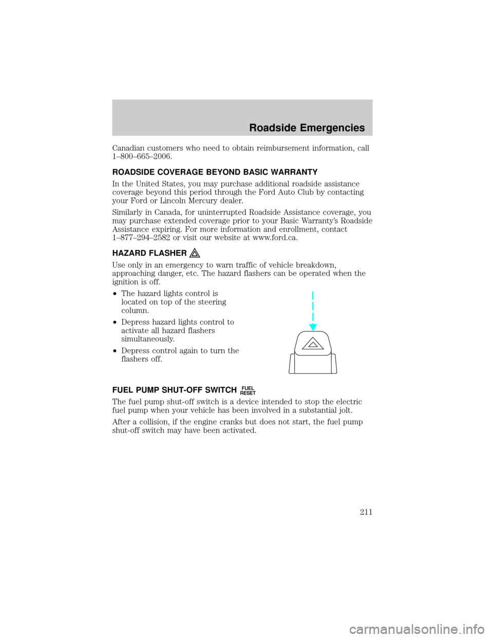
²The hazard lights control is
located on top of the steering
column.
²Depress hazard lights control to
activate all hazard flashers
simultaneously.
²Depress control again to turn the
flashers off.
FUEL PUMP SHUT-OFF SWITCH
FUEL
RESET
The fuel pump shut-off switch is a device intended to stop the electric
fuel pump when your vehicle has been involved in a substantial jolt.
After a collision, if the engine cranks but does not start, the fuel pump
shut-off switch may have been activated.
Roadside Emergencies
211
Page 212 of 320
The fuel pump shut-off switch is
located in the passenger's foot well,
by the kick panel.
Use the following procedure to reset the fuel pump shut-off switch.
1. Turn the ignition to the OFF position.
2. Check the fuel system for leaks.
3. If no fuel leak is apparent, reset the fuel pump shut-off switch by
pushing in on the reset button.
4. Turn the ignition to the ON position. Pause for a few seconds and
return the key to the OFF position.
5. Make a further check for leaks in the fuel system.
Roadside Emergencies
212
Page 265 of 320

If the battery has been disconnected or a new battery has been installed,
the clock and the preset radio stations must be reset once the battery is
reconnected.
²Always dispose of automotive
batteries in a responsible manner.
Follow your local authorized
standards for disposal. Call your
local authorized recycling center
to find out more about recycling
automotive batteries.
ENGINE COOLANT
Checking engine coolant
The concentration and level of engine coolant should be checked at the
mileage intervals listed in the scheduled maintenance guide. The coolant
concentration should be maintained at 50/50 coolant and water, which
equates to a freeze point of -36É C (-34É F). Coolant concentration
testing is possible with a hydrometer or antifreeze tester (such as the
Rotunda Battery and Antifreeze Tester, 014±R1060). The level of coolant
should be maintained at the ªcold fullº of ªcold fill rangeº level in the
coolant reservoir. If the level falls below, add coolant per the instructions
in theAdding Engine Coolantsection.
Your vehicle was factory-filled with a 50/50 engine coolant and water
concentration. If the concentration of coolant falls below 40% or above
60%, the engine parts could become damaged or not work properly.A
50±50 mixture of coolant and water provides the following:
²Freeze protection down to -36É C (-34É F).
²Boiling protection up to 129É C (265É F).
²Protection against rust and other forms of corrosion.
²Enables calibrated gauges to work properly.
LEAD
RETURN
RECYCLE
Maintenance and Specifications
265