Page 6 of 104
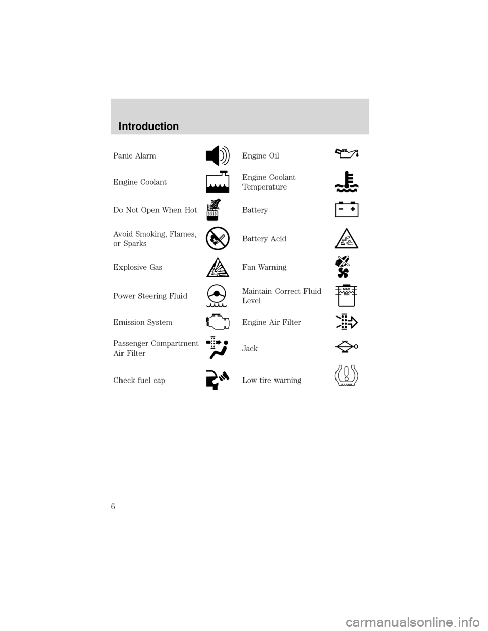
Panic AlarmEngine Oil
Engine CoolantEngine Coolant
Temperature
Do Not Open When HotBattery
Avoid Smoking, Flames,
or SparksBattery Acid
Explosive GasFan Warning
Power Steering FluidMaintain Correct Fluid
LevelMAX
MIN
Emission SystemEngine Air Filter
Passenger Compartment
Air FilterJack
Check fuel capLow tire warning
Introduction
6
Page 22 of 104
STARTING
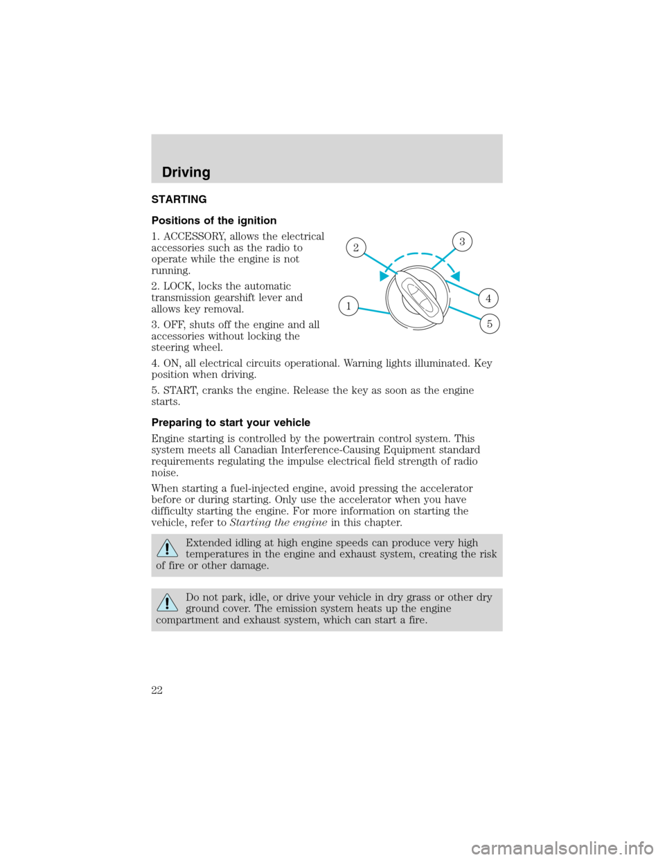
Positions of the ignition
1. ACCESSORY, allows the electrical
accessories such as the radio to
operate while the engine is not
running.
2. LOCK, locks the automatic
transmission gearshift lever and
allows key removal.
3. OFF, shuts off the engine and all
accessories without locking the
steering wheel.
4. ON, all electrical circuits operational. Warning lights illuminated. Key
position when driving.
5. START, cranks the engine. Release the key as soon as the engine
starts.
Preparing to start your vehicle
Engine starting is controlled by the powertrain control system. This
system meets all Canadian Interference-Causing Equipment standard
requirements regulating the impulse electrical field strength of radio
noise.
When starting a fuel-injected engine, avoid pressing the accelerator
before or during starting. Only use the accelerator when you have
difficulty starting the engine. For more information on starting the
vehicle, refer toStarting the enginein this chapter.
Extended idling at high engine speeds can produce very high
temperatures in the engine and exhaust system, creating the risk
of fire or other damage.
Do not park, idle, or drive your vehicle in dry grass or other dry
ground cover. The emission system heats up the engine
compartment and exhaust system, which can start a fire.
1
23
4
5
Driving
22
Page 28 of 104
Hydraulic brake booster system (Hydroboost or Hydromax)
The Hydroboost and Hydromax systems receive fluid pressure from the
power steering pump to provide power assist during braking.
The Hydromax booster receives backup pressure from the reserve
system electric pump whenever the fluid in the power steering system is
not flowing. When the engine is OFF, the pump will turn on if the brake
pedal is applied, or if the ignition is turned to the ON position.
The sound of the pump operating may be heard by the driver, but this is
a normal characteristic of the system.
The reserve system provides reduced braking power, so the vehicle
should be operated under these conditions with caution, and only to seek
service repair and remove the vehicle from the roadway.
For Hydromax-equipped vehicles operating under normal conditions, the
noise of the fluid flowing through the booster may be heard whenever
the brake is applied. This condition is normal. Vehicle service is not
required.
If braking performance or pedal response becomes very poor, even when
the pedal is strongly depressed, it may indicate the presence of air in the
hydraulic system or leakage of fluid. Stop the vehicle safely as soon as
possible and seek service immediately.
ABS warning lamp
ABS
TheABSwarning lamp in the instrument cluster momentarily illuminates
when the ignition is turned to the ON position. If the light remains on
after the vehicle is started, continues to flash or fails to illuminate, have
the system serviced immediately. With the ABS light on, the anti-lock
brake system is disabled and normal braking is still effective unless the
brake warning light also remains illuminated.
With the ABS light on, the anti-lock
brake system is disabled and normal
braking is still effective unless the
brake warning light also remains
illuminated with parking brake
released. (If your brake warning lamp illuminates, have your vehicle
serviced immediately.)
Driving
28
Page 48 of 104
Relay module
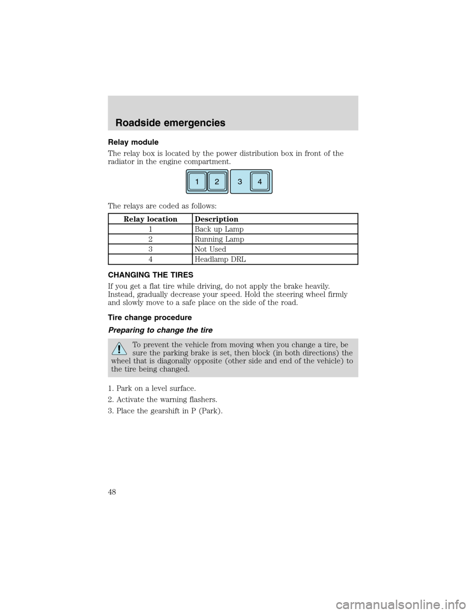
The relay box is located by the power distribution box in front of the
radiator in the engine compartment.
The relays are coded as follows:
Relay location Description
1 Back up Lamp
2 Running Lamp
3 Not Used
4 Headlamp DRL
CHANGING THE TIRES
If you get a flat tire while driving, do not apply the brake heavily.
Instead, gradually decrease your speed. Hold the steering wheel firmly
and slowly move to a safe place on the side of the road.
Tire change procedure
Preparing to change the tire
To prevent the vehicle from moving when you change a tire, be
sure the parking brake is set, then block (in both directions) the
wheel that is diagonally opposite (other side and end of the vehicle) to
the tire being changed.
1. Park on a level surface.
2. Activate the warning flashers.
3. Place the gearshift in P (Park).
12 43
Roadside emergencies
48
Page 60 of 104
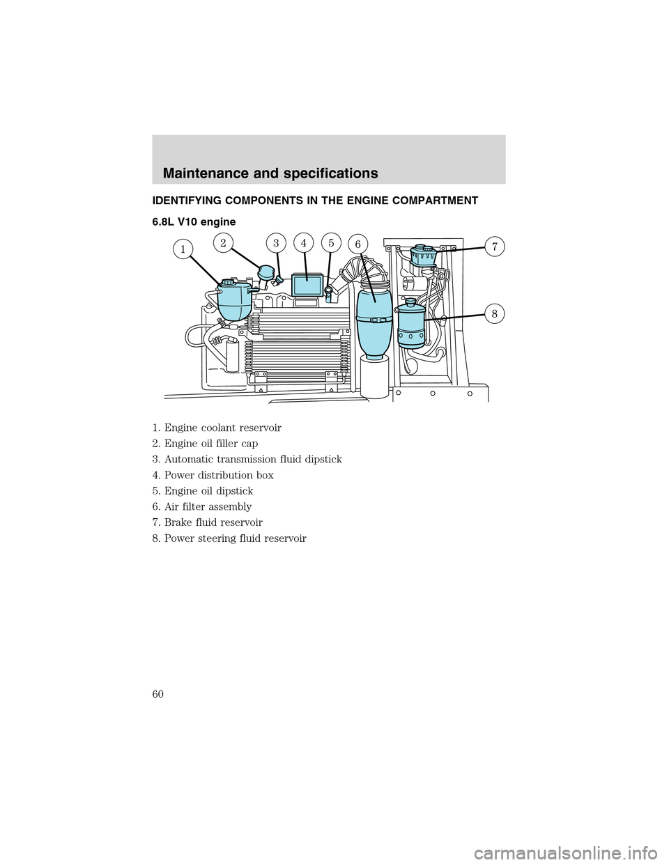
IDENTIFYING COMPONENTS IN THE ENGINE COMPARTMENT
6.8L V10 engine
1. Engine coolant reservoir
2. Engine oil filler cap
3. Automatic transmission fluid dipstick
4. Power distribution box
5. Engine oil dipstick
6. Air filter assembly
7. Brake fluid reservoir
8. Power steering fluid reservoir
Maintenance and specifications
60
Page 71 of 104
How fail-safe cooling works
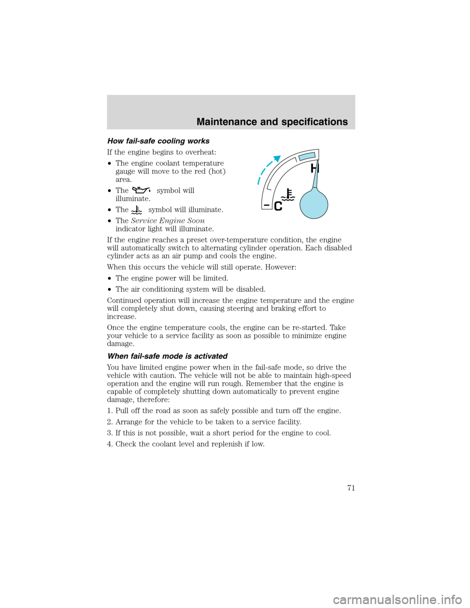
If the engine begins to overheat:
•The engine coolant temperature
gauge will move to the red (hot)
area.
•The
symbol will
illuminate.
•The
symbol will illuminate.
•TheService Engine Soon
indicator light will illuminate.
If the engine reaches a preset over-temperature condition, the engine
will automatically switch to alternating cylinder operation. Each disabled
cylinder acts as an air pump and cools the engine.
When this occurs the vehicle will still operate. However:
•The engine power will be limited.
•The air conditioning system will be disabled.
Continued operation will increase the engine temperature and the engine
will completely shut down, causing steering and braking effort to
increase.
Once the engine temperature cools, the engine can be re-started. Take
your vehicle to a service facility as soon as possible to minimize engine
damage.
When fail-safe mode is activated
You have limited engine power when in the fail-safe mode, so drive the
vehicle with caution. The vehicle will not be able to maintain high-speed
operation and the engine will run rough. Remember that the engine is
capable of completely shutting down automatically to prevent engine
damage, therefore:
1. Pull off the road as soon as safely possible and turn off the engine.
2. Arrange for the vehicle to be taken to a service facility.
3. If this is not possible, wait a short period for the engine to cool.
4. Check the coolant level and replenish if low.
H
C
Maintenance and specifications
71
Page 84 of 104
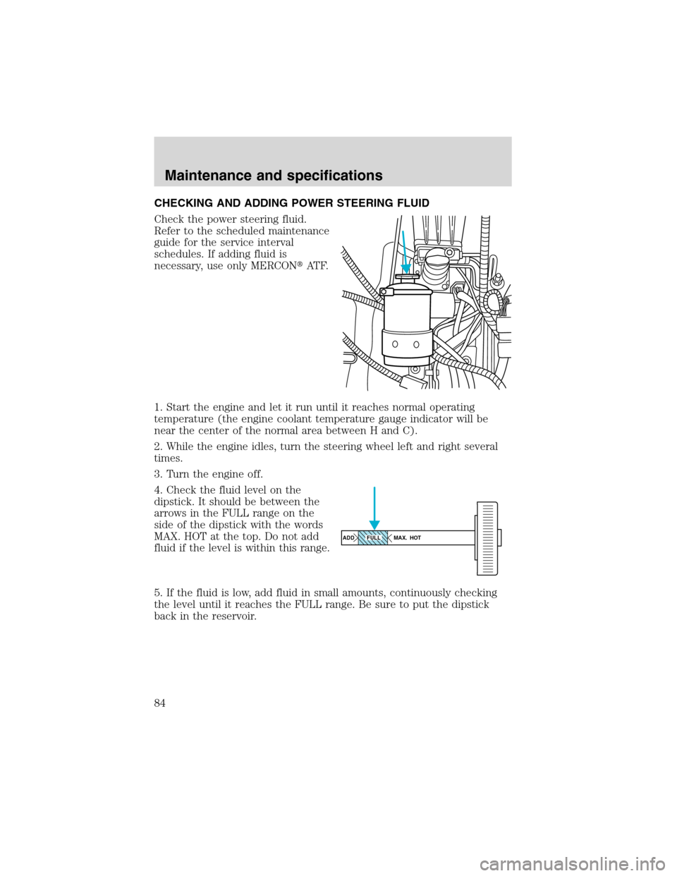
CHECKING AND ADDING POWER STEERING FLUID
Check the power steering fluid.
Refer to the scheduled maintenance
guide for the service interval
schedules. If adding fluid is
necessary, use only MERCON�AT F.
1. Start the engine and let it run until it reaches normal operating
temperature (the engine coolant temperature gauge indicator will be
near the center of the normal area between H and C).
2. While the engine idles, turn the steering wheel left and right several
times.
3. Turn the engine off.
4. Check the fluid level on the
dipstick. It should be between the
arrows in the FULL range on the
side of the dipstick with the words
MAX. HOT at the top. Do not add
fluid if the level is within this range.
5. If the fluid is low, add fluid in small amounts, continuously checking
the level until it reaches the FULL range. Be sure to put the dipstick
back in the reservoir.
ADD MAX. HOTFULL
Maintenance and specifications
84
Page 96 of 104
Fluid Ford Part
NameApplication Capacity
Power steering
fluidMotorcraft
MERCON�AT FAll Keep in FULL
range on
dispstick
Rear axle
2Motorcraft SAE
75W-90
Synthetic Rear
Axle LubricantDana 80 3.9L
(4.0 quarts)3
Motorcraft SAE
80W-90
Synthetic Rear
Axle LubricantDana 135 11.7L
(12.0 quarts)3
Fuel tank N/A All 284.0L
(75 .0 gallons)
Transmission
4Motorcraft
MERCON�AT FAll 16.8L
(17.7 quarts)5
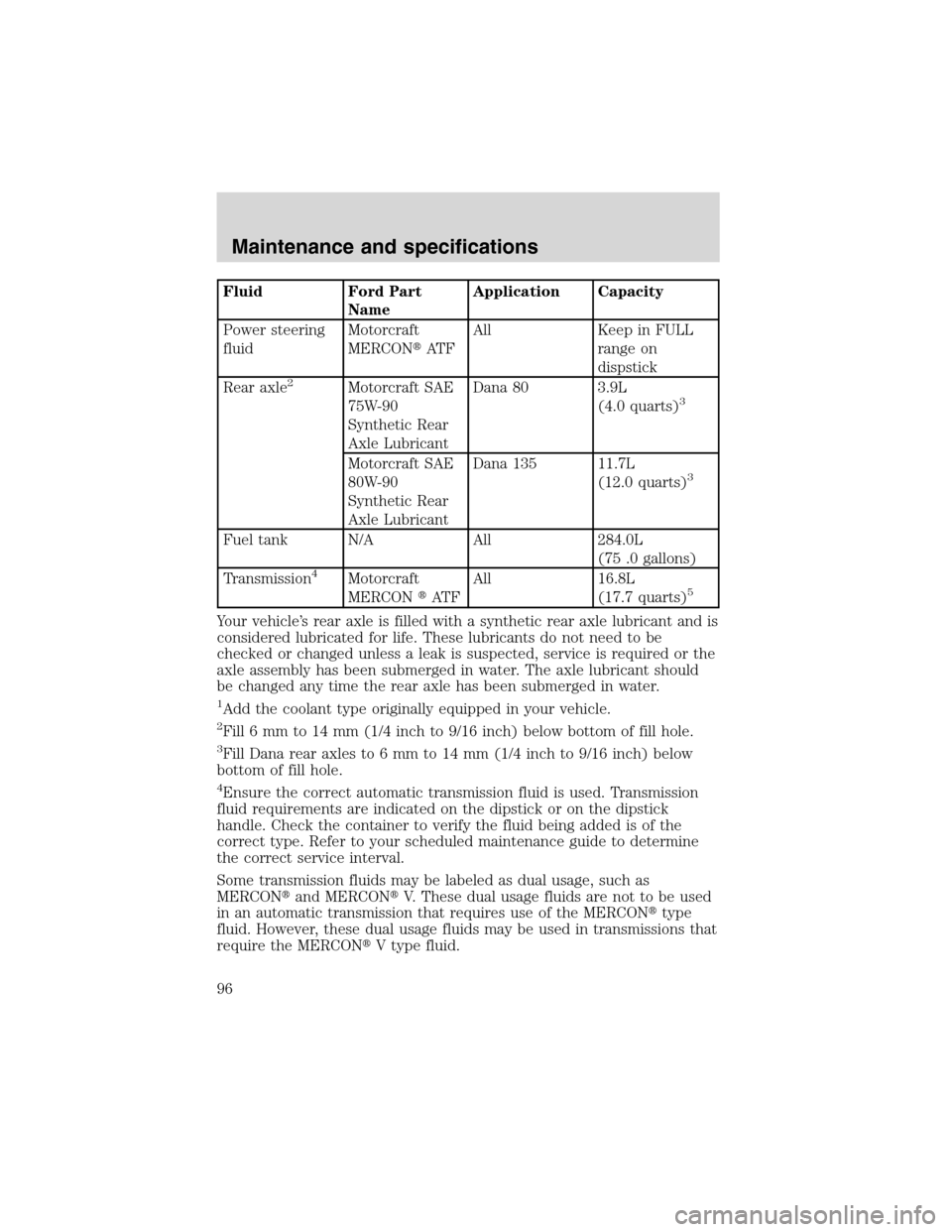
Your vehicle’s rear axle is filled with a synthetic rear axle lubricant and is
considered lubricated for life. These lubricants do not need to be
checked or changed unless a leak is suspected, service is required or the
axle assembly has been submerged in water. The axle lubricant should
be changed any time the rear axle has been submerged in water.
1Add the coolant type originally equipped in your vehicle.
2Fill 6 mm to 14 mm (1/4 inch to 9/16 inch) below bottom of fill hole.
3Fill Dana rear axles to 6 mm to 14 mm (1/4 inch to 9/16 inch) below
bottom of fill hole.
4Ensure the correct automatic transmission fluid is used. Transmission
fluid requirements are indicated on the dipstick or on the dipstick
handle. Check the container to verify the fluid being added is of the
correct type. Refer to your scheduled maintenance guide to determine
the correct service interval.
Some transmission fluids may be labeled as dual usage, such as
MERCON�and MERCON�V. These dual usage fluids are not to be used
in an automatic transmission that requires use of the MERCON�type
fluid. However, these dual usage fluids may be used in transmissions that
require the MERCON�V type fluid.
Maintenance and specifications
96