Page 52 of 200

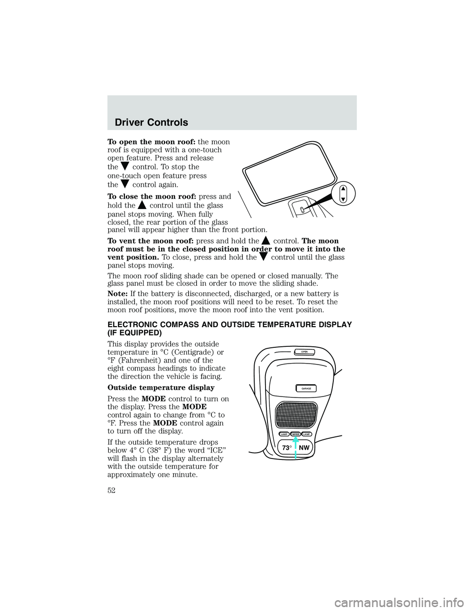
To open the moon roof:the moon
roof is equipped with a one-touch
open feature. Press and release
the
control. To stop the
one-touch open feature press
the
control again.
To close the moon roof:press and
hold the
control until the glass
panel stops moving. When fully
closed, the rear portion of the glass
panel will appear higher than the front portion.
To vent the moon roof:press and hold the
control.The moon
roof must be in the closed position in order to move it into the
vent position.To close, press and hold the
control until the glass
panel stops moving.
The moon roof sliding shade can be opened or closed manually. The
glass panel must be closed in order to move the sliding shade.
Note:If the battery is disconnected, discharged, or a new battery is
installed, the moon roof positions will need to be reset. To reset the
moon roof positions, move the moon roof into the vent position.
ELECTRONIC COMPASS AND OUTSIDE TEMPERATURE DISPLAY
(IF EQUIPPED)
This display provides the outside
temperature in°C (Centigrade) or
°F (Fahrenheit) and one of the
eight compass headings to indicate
the direction the vehicle is facing.
Outside temperature display
Press theMODEcontrol to turn on
the display. Press theMODE
control again to change from°Cto
°F. Press theMODEcontrol again
to turn off the display.
If the outside temperature drops
below 4°C (38°F) the word“ICE”
will flash in the display alternately
with the outside temperature for
approximately one minute.
OPEN
GARAGE
LAMPMODELAMP
73° NW
Driver Controls
52
Page 83 of 200

Failure to inspect and if necessary replace the safety belt
assembly under the above conditions could result in severe
personal injuries in the event of a collision.
Refer toInteriorin theCleaningchapter.
AIR BAG SUPPLEMENTAL RESTRAINT SYSTEM (SRS)
Your vehicle is equipped with a crash sensing and diagnostic module
which records information about the air bag and sensor systems. In the
event of a collision this module may save information related to the
collision including information about the air bag system and impact
severity. This information will assist Ford Motor Company in servicing
the vehicle and in helping to better understand real world collisions and
further improve the safety of future vehicles.
The front passenger air bag is not designed to offer protection to
an occupant in the center front seating position.
OFFLOADEJSHUFDSPMUTE
SELBAL BASS
FADE TREB
SCANTUNE
PUSH ON
CD123456MENUF
SEEKREW FF
C
012345
6RPMx1000
ABS!ENGINE
FUEL
RESETFUEL DOOR EFH
H
HSPEED
CONT
4WD
HIGH
4WD
LOW
O/D
OFFL
L CHECK
GAGE
CHECK
SUSPOVERDRIVE
4X4
HIGH
2WD4X4
LOW
CHECK
ONRSM
SET
ACCEL
COAST
OFF
10MPH 205060
70
304080
90
km/h
0 0 010 100
1
20
10 0 0 0 0 0406080100
120
140
160
180
20
1
2
3
4 A/C
MAX
A/CM
M A
Seating and Safety Restraints
83
Page 126 of 200

If you need to arrange roadside assistance for yourself, Ford Motor
Company will reimburse a reasonable amount. To obtain reimbursement
information, U.S. Ford or Mercury vehicles customers call
1-800-241-3673; Lincoln vehicle customers call 1–800–521–4140.
Canadian customers who need to obtain reimbursement information, call
1–800–665–2006.
Roadside coverage beyond basic warranty
In the United States, you may purchase additional roadside assistance
coverage beyond this period through the Ford Auto Club by contacting
your Ford or Lincoln Mercury dealer.
Similarly in Canada, for uninterrupted Roadside Assistance coverage, you
may purchase extended coverage prior to your Basic Warranty’s Roadside
Assistance expiring. For more information and enrollment, contact
1–877–294–2582 or visit our website at www.ford.ca.
HAZARD FLASHER
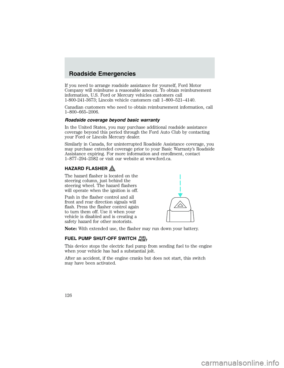
The hazard flasher is located on the
steering column, just behind the
steering wheel. The hazard flashers
will operate when the ignition is off.
Push in the flasher control and all
front and rear direction signals will
flash. Press the flasher control again
to turn them off. Use it when your
vehicle is disabled and is creating a
safety hazard for other motorists.
Note:With extended use, the flasher may run down your battery.
FUEL PUMP SHUT-OFF SWITCH
FUEL
RESET
This device stops the electric fuel pump from sending fuel to the engine
when your vehicle has had a substantial jolt.
After an accident, if the engine cranks but does not start, this switch
may have been activated.
Roadside Emergencies
126
Page 127 of 200
This switch is located in the
passenger’s footwell, by the kick
panel.
To reset the switch:
1. Turn the ignition OFF.
2. Check the fuel system for leaks.
3. If no leaks are apparent, reset the
switch by pushing in on the reset
button.
4. Turn the ignition ON.
5. Wait a few seconds and return
the key to OFF.
6. Make another check of leaks.
FUSES AND RELAYS
If electrical components are not
working, a fuse may have blown. If a
fuses is blown the wire in the fuse
will be broken.
Note:Always replace a fuse with
one that has the specified amperage
rating.
Replacing a blown fuse with a fuse that has a higher amperage
can cause severe wire damage and could start a fire.
15
Roadside Emergencies
127
Page 173 of 200

The following signs could indicate a problem with your emission control
system:
•Fluid leaks
•Strange odors
•Smoke
•Loss of engine power
•Illumination of the charging system, temperature, or“Check Engine”
light in the instrument panel.
Exhaust leaks may result in harmful and potentially lethal fumes
entering the passenger compartment.
It is unlawful to intentionally remove an emission control device or
prevent it from working. Information about your vehicle’s emission
system is on the Vehicle Emission Control Information decal located on
or near the engine.
READINESS FOR INSPECTION/MAINTENANCE (I/M) TESTING
It may be a legal requirement in your area to pass an I/M test of the
on-board diagnostics system. If the system or battery has just been
serviced, the on-board diagnostic system is reset to a“not ready for I/M
test”condition. To ready the system, allow the vehicle to sit for at least
eight hours without starting. Then, start the engine and complete the
following driving cycle:
1. Drive on an expressway or highway for at least 10 minutes.
2. Drive in stop-and-go traffic for at least 20 minutes with a minimum of
four idle periods.
The engine must warm up to its normal operating temperature. Once
started, do not turn off the engine until the above drive cycle is
complete.
Note:If your“Check Engine”light is on, your vehicle may not pass an
I/M test.
Maintenance and Specifications
173