Page 67 of 280
Replacing foglamp bulbs
1. Remove the bulb socket from the
foglamp by turning
counterclockwise.
2. Disconnect the electrical
connector from the foglamp bulb.
3. Connect the new foglamp bulb to the electrical connector.
4. Install the bulb socket in the foglamp turning clockwise.
Replacing running board lamp bulbs
For bulb replacement, see a dealer or qualified technician.
High-mount brakelamp
To change the high-mount
brakelamp bulbs:
1. Remove the four screws from the
high-mount brakelamp assembly.
2. Carefully pull the lamp assembly
away from the vehicle to access the
bulbs.
3. Remove the bulb socket by
turning counterclockwise and a
careful pull.
4. Pull the bulb straight out of the
socket and push in the new bulb.
5. Replace the bulbs as needed and
install the high-mount brakelamp
assembly.
Lights
67
Page 68 of 280
Replacing license plate lamp bulbs
The license plate bulbs are located
behind the rear bumper. To change
the license plate lamp bulbs:
1. Reach behind the rear bumper to
locate the bulb.
2. Twist the bulb socket
counterclockwise and carefully pull
to remove it from the lamp
assembly.
3. Pull out the old bulb from the
socket and push in the new bulb.
4. Install the bulb socket in lamp assembly by turning it clockwise.
Lights
68
Page 72 of 280
Forward storage bin (if equipped)
Press the release control to open
the storage compartment. The door
will open slightly and can be moved
to full open.
The storage compartment may be
used to secure sunglasses or a
similar object.
Installing a garage door opener (if equipped)
The storage compartment can be converted to accommodate a variety of
aftermarket garage door openers:
²Place Velcro hook onto back side of aftermarket transmitter opposite
of actuator control.
²Place transmitter into storage compartment, control down.
²Place the provided height adaptors onto the back of the storage bin
door as needed.
²Press the storage compartment door to activate the transmitter.
Driver controls
72
Page 74 of 280

Trip computer
For information on the trip computer, refer toTrip computerthis
chapter.
Electronic compass (if equipped)
The compass reading may be affected when you drive near large
buildings, bridges, power lines and powerful broadcast antennas.
Magnetic or metallic objects placed in, on or near the vehicle may also
affect compass accuracy.
Usually, when something affects the compass readings, the compass will
correct itself after a few days of operating your vehicle in normal
conditions. If the compass still appears to be inaccurate, a manual
calibration may be necessary. Refer toCompass calibration
adjustment.
Most geographic areas (zones) have a magnetic north compass point that
varies slightly from the northerly direction on maps. This variation is four
degrees between adjacent zones and will become noticeable as the
vehicle crosses multiple zones. A correct zone setting will eliminate this
error. Refer toCompass zone adjustment.
Electronic compass/temperature display (without trip computer)
Outside air temperature
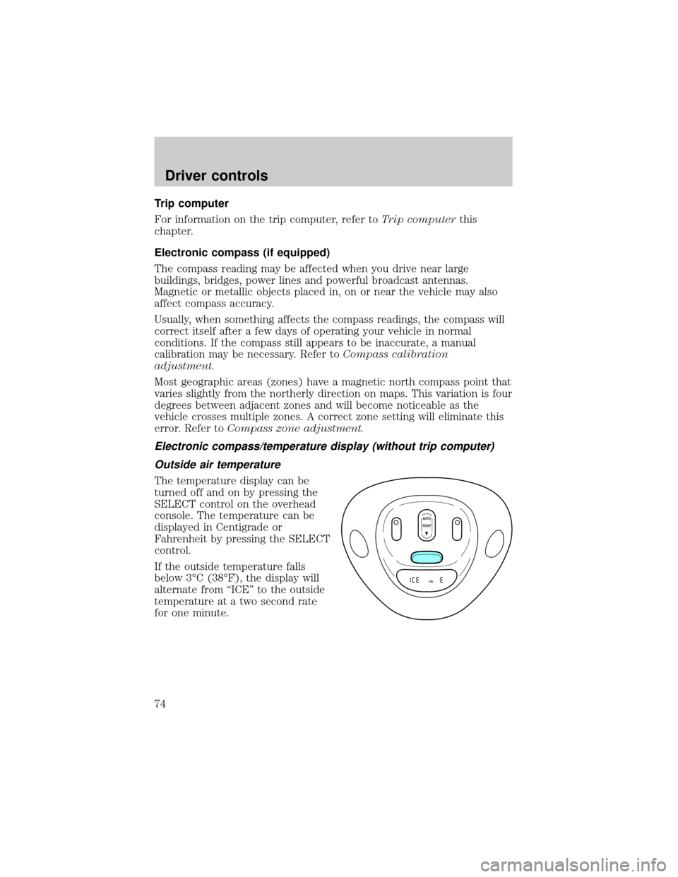
The temperature display can be
turned off and on by pressing the
SELECT control on the overhead
console. The temperature can be
displayed in Centigrade or
Fahrenheit by pressing the SELECT
control.
If the outside temperature falls
below 3ÉC (38ÉF), the display will
alternate from ªICEº to the outside
temperature at a two second rate
for one minute.
AUTO
CAL
ROOF
Driver controls
74
Page 78 of 280
Press theportion of the VENT control to open the power rear
quarter windows.
Press the
portion of the VENT control to close the power rear
quarter windows.
AUXILIARY POWER POINT
Power outlets are designed for
accessory plugs only. Do not
hang any type of accessory or
accessory bracket from the plug.
Improper use of the power
outlet can cause damage not
covered by your warranty.
The auxiliary power point is located
on the instrument panel.
Do not plug optional electrical
accessories into the cigarette lighter. Use the power point.
Power outlets are designed for
accessory plugs only. Do not
hang any type of accessory or
accessory bracket from the plug.
Improper use of the power
outlet can cause damage not
covered by your warranty.
A second auxiliary power point is
located on the lower rear side of the
console. The power point is
accessible from the rear seats.
Driver controls
78
Page 80 of 280

Window lock
The window lock feature allows only
the driver to operate the power
windows.
To lock out all the window controls
except for the driver's press the left
side of the control. Press the right side to restore the window controls.
Accessory delay
With accessory delay, the window switches may be used for up to ten
minutes after the ignition switch is turned to the OFF position or until
any door is opened.
MIRRORS
Automatic dimming rear view mirrors (if equipped)
Your vehicle is equipped with an inside rear view mirror with an
auto-dimming function. The electronic day/night mirror will change from
the normal state to the non-glare state when bright lights (glare) reach
the inside rear view mirror. When the inside rear view mirror detects
bright light from in front of or behind the vehicle, the inside rear view
mirror will automatically adjust (darken) to minimize glare.
Do not block the sensor on the backside of the inside rear view mirror
since this may impair proper system performance.
Press the control to turn the mirror
OFF or AUTO.
The mirror will automatically return
to the normal state whenever the
vehicle is placed in R
(Reverse)(when the mirror is on) to ensure a bright clear view when
backing up.
Power side view mirrors
The ignition can be in any position to adjust the power side view mirrors.
To adjust your mirrors:
WINDOW LOCK
OFF AUTO
Driver controls
80
Page 86 of 280
Pressing OFF will erase the
previously programmed set speed.
To return to a previously set speed
²Press RES. For RES to operate,
the vehicle speed must be faster
than 48 km/h (30 mph).
Indicator light
This light comes on when either the
SET ACCEL or RES controls are
pressed. The vehicle speed must be
at or above 48 km/h (30 mph). It
turns off when the speed control
OFF control is pressed, the brake or
clutch is applied, or the ignition is turned to the OFF position.
HOMELINKTUNIVERSAL TRANSCEIVER (IF EQUIPPED)
The HomeLinktUniversal Transceiver, located on the driver's visor,
provides a convenient way to replace up to three hand-held transmitters
with a single built-in device. This feature will learn the radio frequency
codes of most current transmitters to operate garage doors, entry gates,
security systems, entry door locks, and home or office lighting.
ON
OFF
RES
SET
ACCEL
COAST
Driver controls
86
Page 87 of 280

When programming your HomeLinktUniversal Transceiver, to a
garage door or gate be sure that people and objects are out of
the way to prevent potential harm or damage.
Do not use the HomeLinktUniversal Transceiver with any garage door
opener that lacks safety stop and reverse features as required by U.S.
federal safety standards (this includes any garage door opener model
manufactured before April 1, 1982). A garage door which cannot detect
an object, signaling the door to stop and reverse, does not meet current
U.S. federal safety standards. For more information on this matter, call
toll-free: 1±800±355±3515 or on the Internet atHomeLink.jci.com.
Programming
Do not program the HomeLinktUniversal Transceiver with the
vehicle parked in the garage.
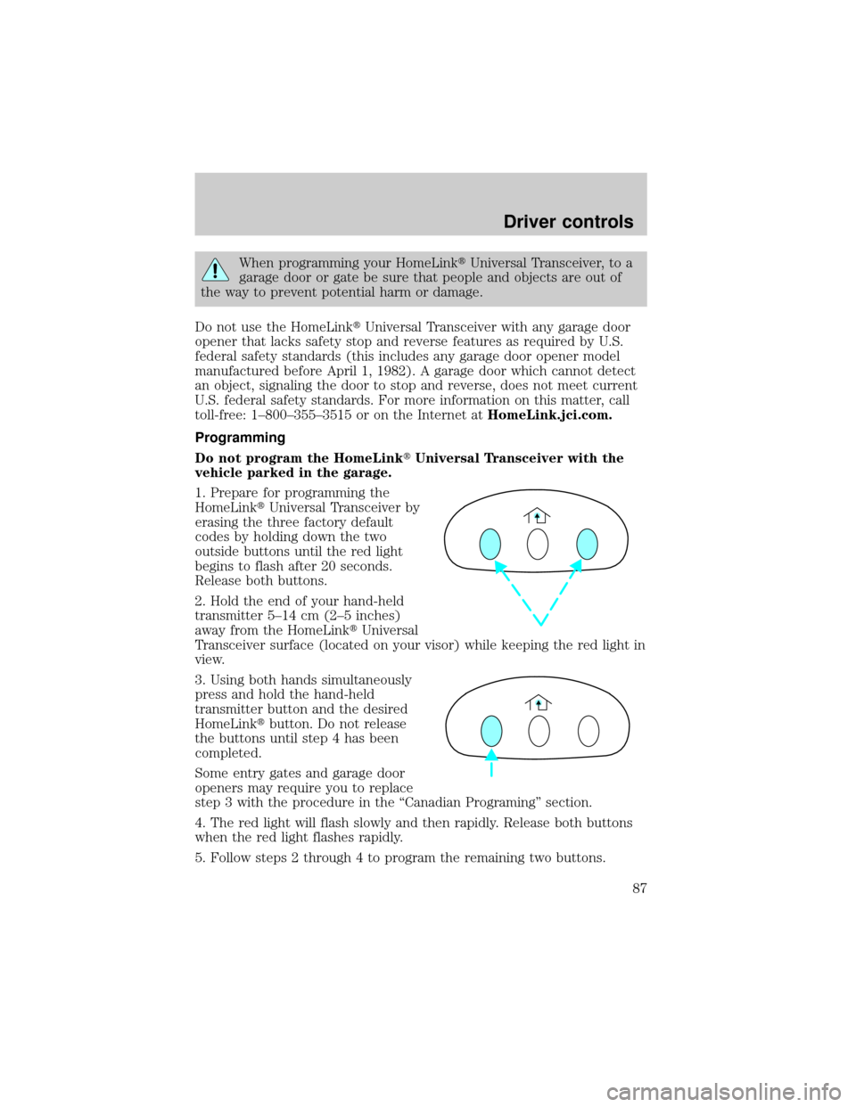
1. Prepare for programming the
HomeLinktUniversal Transceiver by
erasing the three factory default
codes by holding down the two
outside buttons until the red light
begins to flash after 20 seconds.
Release both buttons.
2. Hold the end of your hand-held
transmitter 5±14 cm (2±5 inches)
away from the HomeLinktUniversal
Transceiver surface (located on your visor) while keeping the red light in
view.
3. Using both hands simultaneously
press and hold the hand-held
transmitter button and the desired
HomeLinktbutton. Do not release
the buttons until step 4 has been
completed.
Some entry gates and garage door
openers may require you to replace
step 3 with the procedure in the ªCanadian Programingº section.
4. The red light will flash slowly and then rapidly. Release both buttons
when the red light flashes rapidly.
5. Follow steps 2 through 4 to program the remaining two buttons.
Driver controls
87