Page 75 of 256

AUXILIARY HEATER AND AIR CONDITIONER (IF EQUIPPED)
If your vehicle is equipped with a
factory installed auxiliary unit, the
main climate control panel will
include separate controls for the
front fan speed and the rear fan
speed. In conjunction with the front
fan speed control, an additional fan
speed control is located overhead
between the second and third row
seating.
The fan speed of the auxiliary unit
can be controlled either by the front
seat using the front auxiliary control
or by the rear seat passengers using
the rear auxiliary control, but not
both. To control the auxiliary unit
using the rear control, the front
control must be in the REAR position.
Air temperature and air distribution are dependent upon the mode that
is selected on the main climate control panel:
•MAX A/C-Distributes recirculated air conditioning through the
overhead vents of the rear compartment.
•NORM A/C-Distributes recirculated air conditioning through the
overhead vents of the rear compartment.
•VENT-Distributes recirculated ambient air through the overhead vents
of the rear compartment.
•
OFF-No air, cooled, ambient, or heated, is distributed through any vents
•FLR-Distributes heated air through the floor vents of the rear
compartment.
•MIX-Distributes heated air through the floor vents of the rear
compartment.
•
(Defrost)-Distributes heated air through the floor vents of the
rear compartment.
REAR
OFF HI
LO
REAR
CTRL
OFF
HI
Climate Controls
75
ProCarManuals.com
Page 86 of 256
Never adjust the steering wheel when the vehicle is moving.
AUXILIARY POWER POINT
Power outlets are designed for
accessory plugs only. Do not
hang any type of accessory or
accessory bracket from the plug.
Improper use of the power
outlet can cause damage not
covered by your warranty.
The auxiliary power point is located
on the instrument panel.
A second power point (if equipped)
is located behind the driver’s seat on the upper trim panel.
Do not plug optional electrical accessories into the cigarette
lighter. Use the power point.
POWER WINDOWS (IF EQUIPPED)
Press and hold the rocker switches to open and close windows.
•Press the top portion of the
rocker switch to close.
•Press the bottom portion of the
rocker switch to open.
Driver Controls
86
ProCarManuals.com
Page 164 of 256

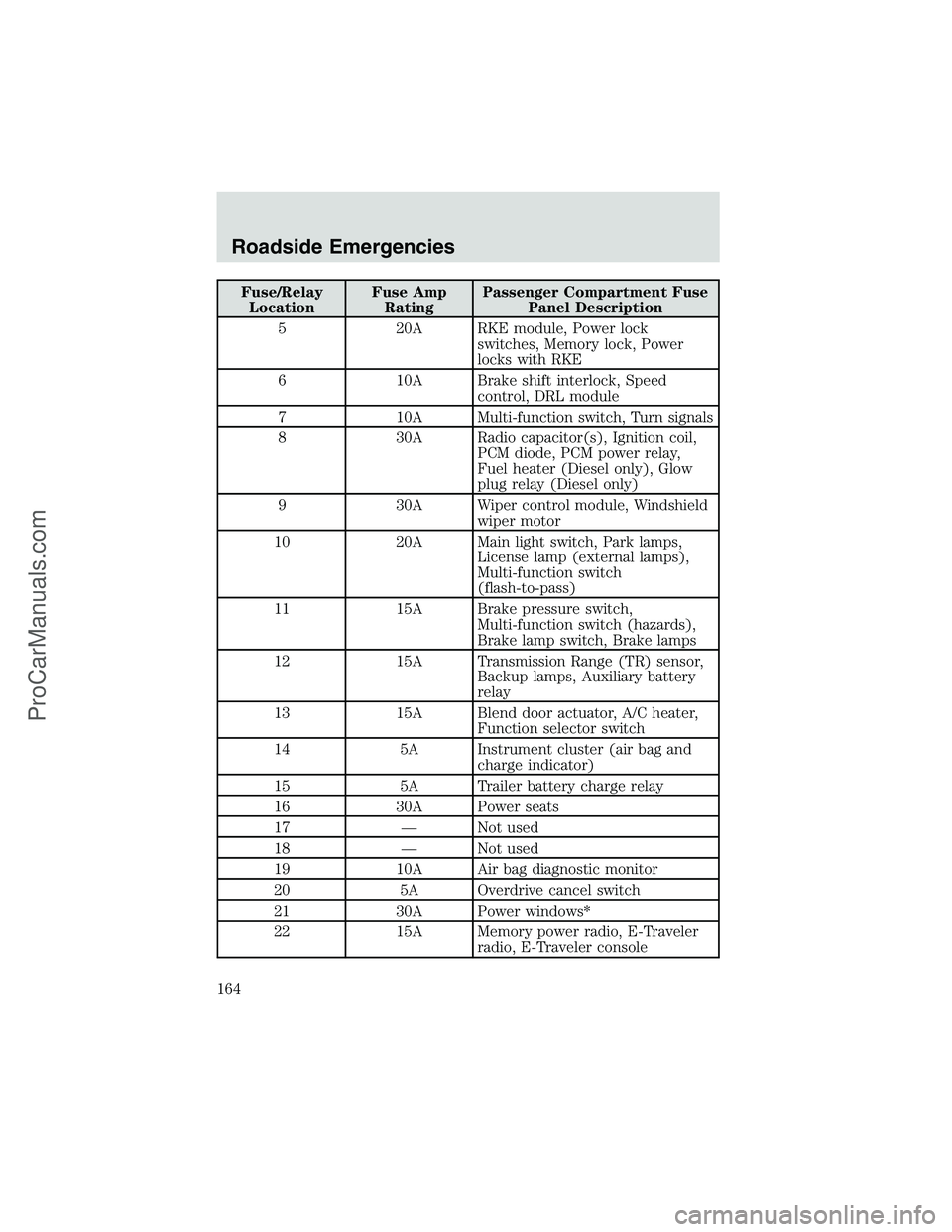
Fuse/Relay
LocationFuse Amp
RatingPassenger Compartment Fuse
Panel Description
5 20A RKE module, Power lock
switches, Memory lock, Power
locks with RKE
6 10A Brake shift interlock, Speed
control, DRL module
7 10A Multi-function switch, Turn signals
8 30A Radio capacitor(s), Ignition coil,
PCM diode, PCM power relay,
Fuel heater (Diesel only), Glow
plug relay (Diesel only)
9 30A Wiper control module, Windshield
wiper motor
10 20A Main light switch, Park lamps,
License lamp (external lamps),
Multi-function switch
(flash-to-pass)
11 15A Brake pressure switch,
Multi-function switch (hazards),
Brake lamp switch, Brake lamps
12 15A Transmission Range (TR) sensor,
Backup lamps, Auxiliary battery
relay
13 15A Blend door actuator, A/C heater,
Function selector switch
14 5A Instrument cluster (air bag and
charge indicator)
15 5A Trailer battery charge relay
16 30A Power seats
17—Not used
18—Not used
19 10A Air bag diagnostic monitor
20 5A Overdrive cancel switch
21 30A Power windows*
22 15A Memory power radio, E-Traveler
radio, E-Traveler console
Roadside Emergencies
164
ProCarManuals.com
Page 167 of 256

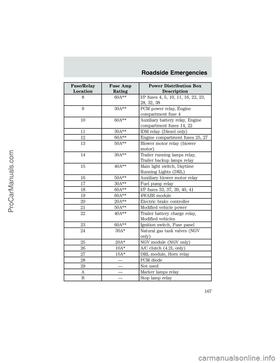
Fuse/Relay
LocationFuse Amp
RatingPower Distribution Box
Description
8 60A** I/P fuses 4, 5, 10, 11, 16, 22, 23,
28, 32, 38
9 30A** PCM power relay, Engine
compartment fuse 4
10 60A** Auxiliary battery relay, Engine
compartment fuses 14, 22
11 30A** IDM relay (Diesel only)
12 60A** Engine compartment fuses 25, 27
13 50A** Blower motor relay (blower
motor)
14 30A** Trailer running lamps relay,
Trailer backup lamps relay
15 40A** Main light switch, Daytime
Running Lights (DRL)
16 50A** Auxiliary blower motor relay
17 30A** Fuel pump relay
18 60A** I/P fuses 33, 37, 39, 40, 41
19 60A** 4WABS module
20 20A** Electric brake controller
21 50A** Modified vehicle power
22 40A** Trailer battery charge relay,
Modified vehicles
23 60A** Ignition switch, Fuse panel
24 30A* Natural gas tank valves (NGV
only)
25 20A* NGV module (NGV only)
26 10A* A/C clutch (4.2L only)
27 15A* DRL module, Horn relay
28—PCM diode
29—Not used
A—Marker lamps relay
B—Stop lamp relay
Roadside Emergencies
167
ProCarManuals.com
Page 199 of 256
OPENING THE HOOD
1. Inside the vehicle, pull the hood
release handle located under the
bottom left corner of the instrument
panel.
2. Go to the front of the vehicle and release the auxiliary latch that is
located in the center top of the grill.
3. Lift the hood and secure it with the prop rod.
IDENTIFYING COMPONENTS IN THE ENGINE COMPARTMENT
Engine compartment component locations
Refer to the7.3 Liter Power Stroke Direct Injection Turbo Diesel
Owner’s Guide Supplementfor diesel engine component locations.
HOOD
Maintenance and Specifications
199
ProCarManuals.com
Page 206 of 256
If the battery has been disconnected or a new battery has been installed,
the clock and radio settings must be reset once the battery is
reconnected.
•Always dispose of automotive
batteries in a responsible manner.
Follow your local authorized
standards for disposal. Call your
local authorized recycling center
to find out more about recycling
automotive batteries.
Disconnecting dual batteries (if equipped)
The primary battery is located under the hood.
The auxiliary battery is located on the passenger side frame rail.
LEAD
RETURN
RECYCLE
Maintenance and Specifications
206
ProCarManuals.com
Page 207 of 256
Gasoline engines
Disconnect:
1. Disconnect the primary battery
ground cable.
2. Disconnect the auxiliary battery
frame ground.
•Remove the ground bolt.
•Pull the cable away from the
frame and make sure that the
cable does not contact the frame.
Connect:
1. Reconnect the auxiliary battery
frame ground.
Maintenance and Specifications
207
ProCarManuals.com
Page 235 of 256

tires and chains. If you need to use chains, it is recommended that steel
wheels (of the same size and specifications) be used, as chains may chip
aluminum wheels.
Follow these guidelines when using snow tires and chains:
•Use only SAE Class S chains.
•Install chains securely, verifying that the chains do not touch any
wiring, brake lines or fuel lines.
•Drive cautiously. If you hear the chains rub or bang against your
vehicle, stop and re-tighten the chains. If this does not work, remove
the chains to prevent damage to your vehicle.
•If possible, avoid fully loading your vehicle.
•Remove the tire chains when they are no longer needed. Do not use
tire chains on dry roads.
•The suspension insulation and bumpers will help prevent vehicle
damage. Do not remove these components from your vehicle when
using snow tires and chains.
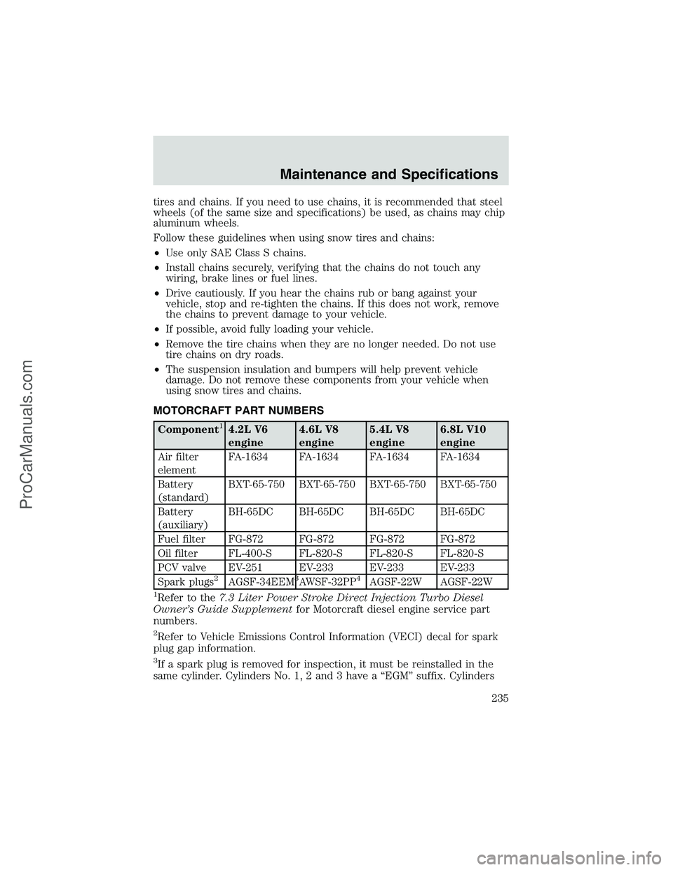
MOTORCRAFT PART NUMBERS
Component14.2L V6
engine4.6L V8
engine5.4L V8
engine6.8L V10
engine
Air filter
elementFA-1634 FA-1634 FA-1634 FA-1634
Battery
(standard)BXT-65-750 BXT-65-750 BXT-65-750 BXT-65-750
Battery
(auxiliary)BH-65DC BH-65DC BH-65DC BH-65DC
Fuel filter FG-872 FG-872 FG-872 FG-872
Oil filter FL-400-S FL-820-S FL-820-S FL-820-S
PCV valve EV-251 EV-233 EV-233 EV-233
Spark plugs
2AGSF-34EEM3AWSF-32PP4AGSF-22W AGSF-22W
1Refer to the7.3 Liter Power Stroke Direct Injection Turbo Diesel
Owner’s Guide Supplementfor Motorcraft diesel engine service part
numbers.
2Refer to Vehicle Emissions Control Information (VECI) decal for spark
plug gap information.
3If a spark plug is removed for inspection, it must be reinstalled in the
same cylinder. Cylinders No. 1, 2 and 3 have a“EGM”suffix. Cylinders
Maintenance and Specifications
235
ProCarManuals.com