Page 2 of 256
Locks and Security 97
Keys 97
Locks 97
Anti-theft system 97
Seating and Safety Restraints 101
Seating 101
Safety restraints 109
Air bags 119
Child restraints 124
Driving 136
Starting 136
Brakes 140
Transmission operation 145
Vehicle loading 149
Trailer towing 151
Roadside Emergencies 158
Getting roadside assistance 158
Hazard flasher switch 159
Fuel pump shut-off switch 160
Fuses and relays 161
Changing tires 168
Jump starting 175
Wrecker towing 180
Customer Assistance 181
Reporting safety defects (U.S. only) 190
Table of Contents
2
ProCarManuals.com
Page 121 of 256

Do not attempt to service, repair, or modify the air bag
supplemental restraint systems or its fuses. See your Ford or
Lincoln Mercury dealer.
Modifications to the front end of the vehicle, including frame,
bumper, front end body structure and tow hooks may affect the
performance of the air bag sensors increasing the risk of injury. Do not
modify the front end of the vehicle.
Additional equipment may affect the performance of the air bag
sensors increasing the risk of injury. Please refer to the Body
Builders Layout Book for instructions about the appropriate installation
of additional equipment.
Children and air bags
For additional important safety
information, read all information on
safety restraints in this guide.
Children must always be properly
restrained. Accident statistics
suggest that children are safer when
properly restrained in the rear
seating positions than in the front
seating position. Failure to follow
these instructions may increase the
risk of injury in a collision.
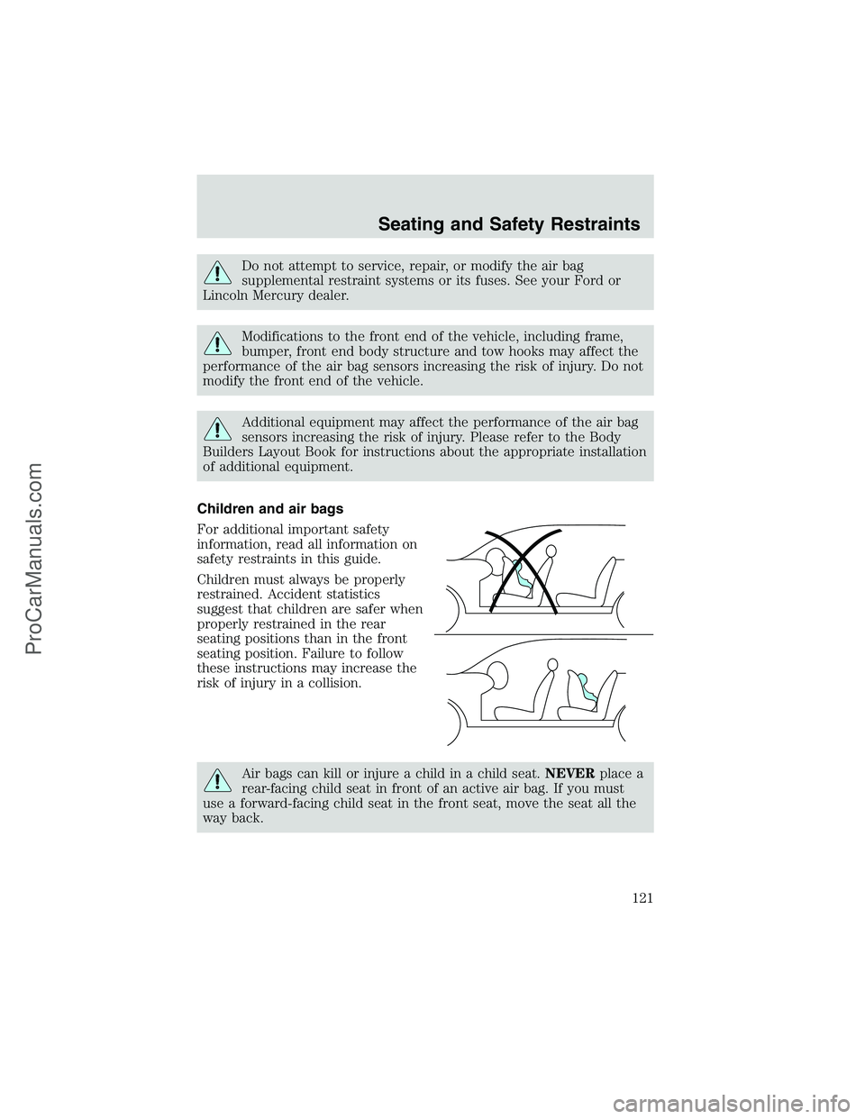
Air bags can kill or injure a child in a child seat.NEVERplace a
rear-facing child seat in front of an active air bag. If you must
use a forward-facing child seat in the front seat, move the seat all the
way back.
Seating and Safety Restraints
121
ProCarManuals.com
Page 145 of 256

AUTOMATIC TRANSMISSION OPERATION
Brake-shift interlock
This vehicle is equipped with a brake-shift interlock feature that prevents
the gearshift lever from being moved from P (Park) when the ignition is
in the ON position unless the brake pedal is depressed.
If you cannot move the gearshift lever out of P (Park) with ignition in
the ON position and the brake pedal depressed:
1. Apply the parking brake, turn ignition key to LOCK, then remove the
key.
2. Insert the key and turn it to OFF.Apply the brake pedal and shift
to N (Neutral).
In the ignition OFF position, the automatic transmission shift
lever can be moved from the P (Park) position without the brake
pedal depressed. To avoid unwanted vehicle movement, always set the
parking brake.
3. Start the vehicle.
If it is necessary to use the above procedure to move the gearshift lever,
it is possible that a fuse has blown or the vehicle’s brakelamps are not
operating properly. Refer toFuses and relaysin theRoadside
emergencieschapter.
Do not drive your vehicle until you verify that the brakelamps
are working.
If your vehicle gets stuck in mud or snow it may be rocked out by
shifting from forward and reverse gears, stopping between shifts, in a
steady pattern. Press lightly on the accelerator in each gear.
Do not rock the vehicle if the engine is not at normal operating
temperature or damage to the transmission may occur.
Do not rock the vehicle for more than a few minutes or damage
to the transmission and tires may occur or the engine may
overheat.
Always set the parking brake fully and make sure the gearshift is
latched in P (Park). Turn the ignition to the LOCK position and
remove the key whenever you leave your vehicle.
Driving
145
ProCarManuals.com
Page 161 of 256
For commercial stripped chassis
vehicles, the fuel pump shut-off
switch is located on a bracket above
the brake pedal.
Use the following procedure to reset the fuel pump shut-off switch.
1. Turn the ignition to the OFF position.
2. Check the fuel system for leaks.
3. If no fuel leak is apparent, reset the fuel pump shut-off switch by
pushing in on the reset button.
4. Turn the ignition to the ON position. Pause for a few seconds and
return the key to the OFF position.
5. Make a further check for leaks in the fuel system.
FUSES AND RELAYS
Fuses
If electrical components in the
vehicle are not working, a fuse may
have blown. Blown fuses are
identified by a broken wire within
the fuse. Check the appropriate
fuses before replacing any electrical
components.
15
Roadside Emergencies
161
ProCarManuals.com
Page 162 of 256
Note:Always replace a fuse with one that has the specified amperage
rating. Using a fuse with a higher amperage rating can cause severe wire
damage and could start a fire.
Standard fuse amperage rating and color
COLOR
Fuse
ratingMini
fusesStandard
fusesMaxi
fusesCartridge
maxi
fusesFuse link
cartridge
2A Grey Grey———
3A Violet Violet———
4A Pink Pink———
5A Tan Tan———
7.5A Brown Brown———
10A Red Red———
15A Blue Blue———
20A Yellow Yellow Yellow Blue Blue
25A Natural Natural———
30A Green Green Green Pink Pink
40A——Orange Green Green
50A——Red Red Red
60A——Blue—Yellow
70A——Ta n—Brown
80A——Natural—Black
Passenger compartment fuse panel
The fuse panel is located below and to the left of the steering wheel by
the brake pedal. Remove the panel cover to access the fuses.
To remove a fuse use the fuse puller tool provided on the fuse panel
cover.
Roadside Emergencies
162
ProCarManuals.com
Page 163 of 256
The fuses are coded as follows.
Fuse/Relay
LocationFuse Amp
RatingPassenger Compartment Fuse
Panel Description
1 20A 4WABS module
2 15A Brake warning lamp, Instrument
cluster, Warning chime, 4WABS
relay, Warning indicators, Low
vacuum warning switch (Diesel
only)
3 15A Main light switch, RKE module,
Radio, Instrument illumination,
E-Traveler VCP and video
screens, Overhead console
4 15A Power locks w/RKE, Illuminated
entry, Warning chime, Modified
vehicle, Main light switch,
Courtesy lamps
1234
5
7
689101142
43
44 13 12 14
15 16 17
19 18
2021 22 23
25 24
26 27 28 29
31 30 32 33 3435
37
3638 3940
41
Roadside Emergencies
163
ProCarManuals.com
Page 165 of 256

Fuse/Relay
LocationFuse Amp
RatingPassenger Compartment Fuse
Panel Description
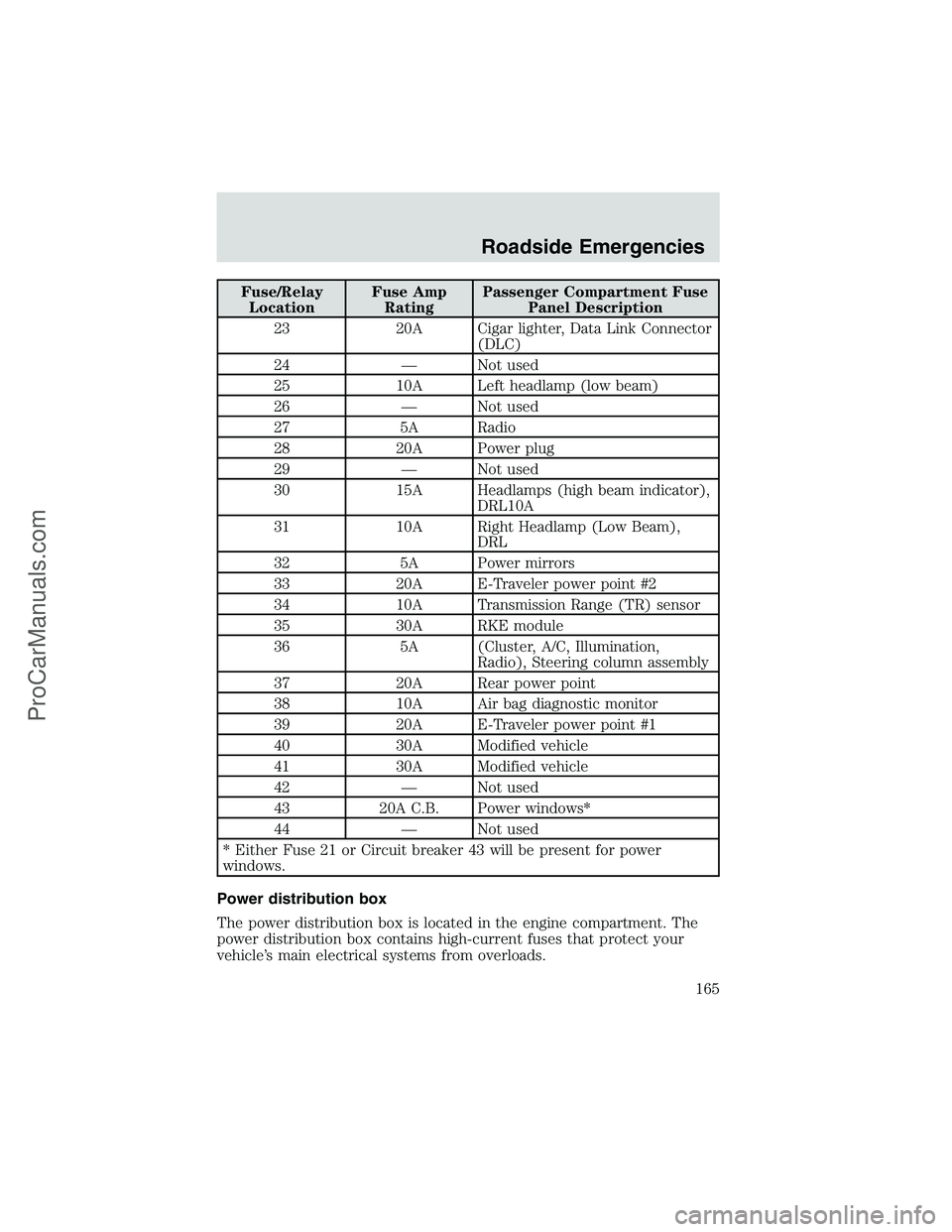
23 20A Cigar lighter, Data Link Connector
(DLC)
24—Not used
25 10A Left headlamp (low beam)
26—Not used
27 5A Radio
28 20A Power plug
29—Not used
30 15A Headlamps (high beam indicator),
DRL10A
31 10A Right Headlamp (Low Beam),
DRL
32 5A Power mirrors
33 20A E-Traveler power point #2
34 10A Transmission Range (TR) sensor
35 30A RKE module
36 5A (Cluster, A/C, Illumination,
Radio), Steering column assembly
37 20A Rear power point
38 10A Air bag diagnostic monitor
39 20A E-Traveler power point #1
40 30A Modified vehicle
41 30A Modified vehicle
42—Not used
43 20A C.B. Power windows*
44—Not used
* Either Fuse 21 or Circuit breaker 43 will be present for power
windows.
Power distribution box
The power distribution box is located in the engine compartment. The
power distribution box contains high-current fuses that protect your
vehicle’s main electrical systems from overloads.
Roadside Emergencies
165
ProCarManuals.com
Page 166 of 256
Always disconnect the battery before servicing high current
fuses.
Always replace the cover to the power distribution box before
reconnecting the battery or refilling fluid reservoirs
If the battery has been disconnected and reconnected, refer to the
Batterysection of theMaintenance and specificationschapter.
The high-current fuses are coded as follows.
Fuse/Relay
LocationFuse Amp
RatingPower Distribution Box
Description
1—Not used
2—Not used
3—Not used
4 10A* Powertrain Control Module (PCM)
Keep Alive Memory, Instrument
cluster, Voltmeter
5 10A* Right trailer turn signal
6 10A* Left trailer turn signal
7 20A* Clearance lamps
AB3
2
146 5715 14 13 12 11 10 9 823 22 21 20 19 18 17 1624 26 25 27
29
CDG F EK J H
28
Roadside Emergencies
166
ProCarManuals.com