Page 66 of 240
²Turn signal lamps
²Backup lamps
²License plate lamp
Do not remove lamp bulbs unless they will be replaced immediately. If a
bulb is removed for an extended period of time, contaminants may enter
the lamp housings and affect performance.
Using the right bulbs
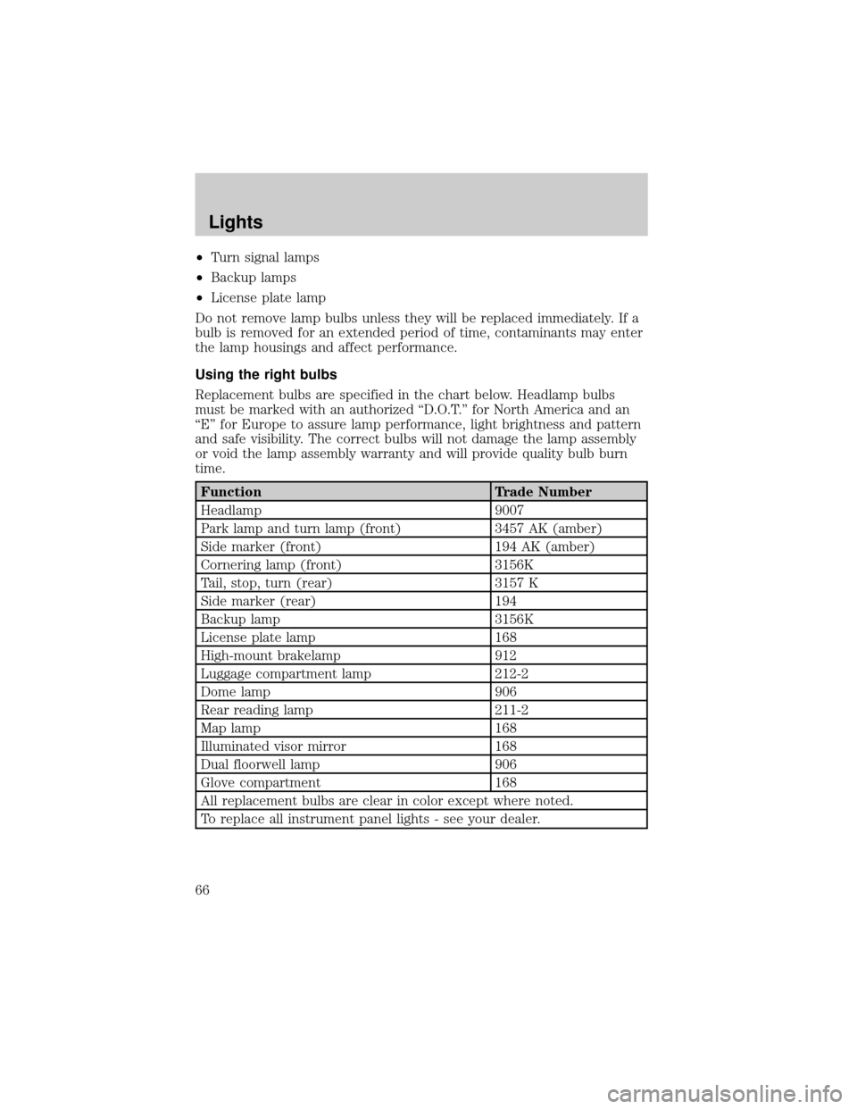
Replacement bulbs are specified in the chart below. Headlamp bulbs
must be marked with an authorized ªD.O.T.º for North America and an
ªEº for Europe to assure lamp performance, light brightness and pattern
and safe visibility. The correct bulbs will not damage the lamp assembly
or void the lamp assembly warranty and will provide quality bulb burn
time.
Function Trade Number
Headlamp 9007
Park lamp and turn lamp (front) 3457 AK (amber)
Side marker (front) 194 AK (amber)
Cornering lamp (front) 3156K
Tail, stop, turn (rear) 3157 K
Side marker (rear) 194
Backup lamp 3156K
License plate lamp 168
High-mount brakelamp 912
Luggage compartment lamp 212-2
Dome lamp 906
Rear reading lamp 211-2
Map lamp 168
Illuminated visor mirror 168
Dual floorwell lamp 906
Glove compartment 168
All replacement bulbs are clear in color except where noted.
To replace all instrument panel lights - see your dealer.
Lights
66
Page 74 of 240
AUXILIARY POWER POINT
The auxiliary power point is located under the instrument panel on the
left hand side of the front passenger foot well. This outlet should be
used in place of the cigarette lighter for optional electrical accessories.
Power outlets are designed for accessory plugs only. Do not hang
any type of accessory or accessory bracket from the plug.
Improper use of the power outlet can cause damage not covered
by your warranty.
POWER WINDOWS
Press and hold the rocker switches to open and close windows.
²Press the top portion of the
rocker switch to close.
²Press the bottom portion of the
rocker switch to open.
AUTO
AUTO
Driver Controls
74
Page 101 of 240
THEFT INDICATOR
The theft indicator is located on top of the instrument panel.
²When the ignition is in the OFF position, the indicator will flash once
every 2 seconds to indicate the SecuriLockysystem is functioning as
a theft deterrent.
²When the ignition is in the ON position, the indicator will glow for 3
seconds to indicate normal system functionality.
If a problem occurs with the SecuriLockysystem, the indicator will flash
rapidly or glow steadily when the ignition is in the ON position. If this
occurs, the vehicle should be taken to an authorized dealer for service.
Automatic arming
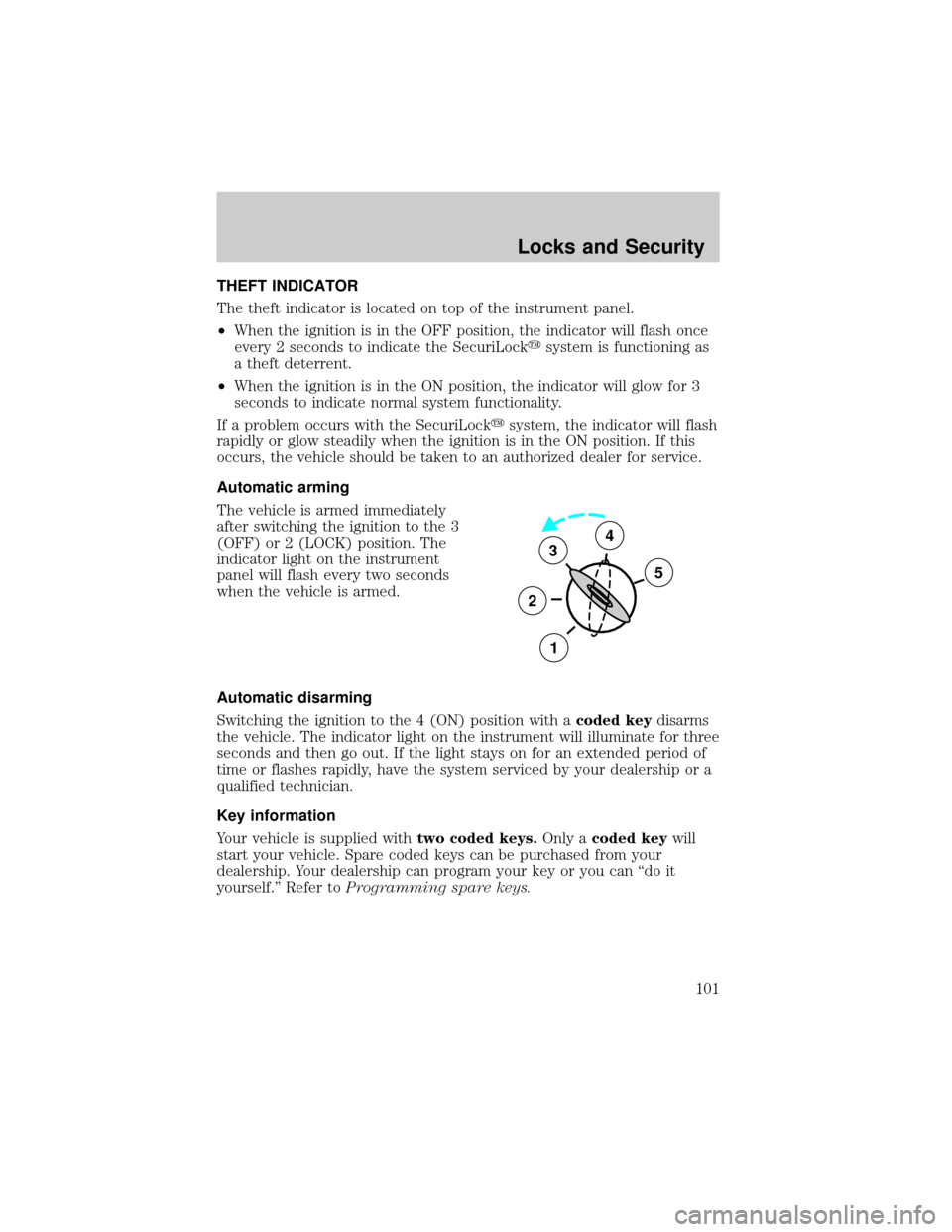
The vehicle is armed immediately
after switching the ignition to the 3
(OFF) or 2 (LOCK) position. The
indicator light on the instrument
panel will flash every two seconds
when the vehicle is armed.
Automatic disarming
Switching the ignition to the 4 (ON) position with acoded keydisarms
the vehicle. The indicator light on the instrument will illuminate for three
seconds and then go out. If the light stays on for an extended period of
time or flashes rapidly, have the system serviced by your dealership or a
qualified technician.
Key information
Your vehicle is supplied withtwo coded keys.Only acoded keywill
start your vehicle. Spare coded keys can be purchased from your
dealership. Your dealership can program your key or you can ªdo it
yourself.º Refer toProgramming spare keys.
3
2
1
5
4
Locks and Security
101
Page 145 of 240
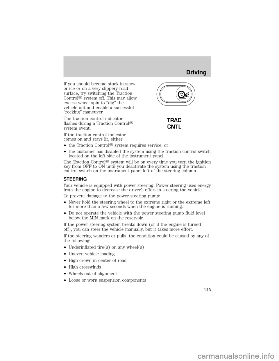
If you should become stuck in snow
or ice or on a very slippery road
surface, try switching the Traction
Controlysystem off. This may allow
excess wheel spin to ªdigº the
vehicle out and enable a successful
ªrockingº maneuver.
The traction control indicator
flashes during a Traction Controly
system event.
If the traction control indicator
comes on and stays lit, either:
²the Traction Controlysystem requires service, or
²the customer has disabled the system using the traction control switch
located on the left side of the instrument panel.
The Traction Controlysystem will be on every time you turn the ignition
key from OFF to ON until you deactivate the system using the traction
control switch on the instrument panel left of the steering column.
STEERING
Your vehicle is equipped with power steering. Power steering uses energy
from the engine to decrease the driver's effort in steering the vehicle.
To prevent damage to the power steering pump:
²Never hold the steering wheel to the extreme right or the extreme left
for more than a few seconds when the engine is running.
²Do not operate the vehicle with the power steering pump fluid level
below the MIN mark on the reservoir.
If the power steering system breaks down (or if the engine is turned
off), you can steer the vehicle manually, but it takes more effort.
If the steering wanders or pulls, the condition could be caused by any of
the following:
²Underinflated tire(s) on any wheel(s)
²Uneven vehicle loading
²High crown in center of road
²High crosswinds
²Wheels out of alignment
²Loose or worn suspension components
TRAC
CNTL
Driving
145
Page 160 of 240
Passenger compartment fuse panel
The fuse panel is located below and to the left of the steering wheel by
the brake pedal. Remove the panel cover to access the fuses.
To remove a fuse use the fuse puller tool provided on the fuse panel
cover.
The fuses are coded as follows.
Fuse/Relay
LocationFuse Amp
RatingPassenger Compartment Fuse
Panel Description
1 Ð Not Used
2 Ð Not Used
3 Ð Not Used
4 10A Air Bags
5 Ð Not Used
6 15A Instrument Cluster, Warning
Lamps Module, Transmission
Control Switch, Lighting Control
Module (LCM)
7 Ð Not Used
27 25
26 2423 21
2219
20
18 16
17 1514 12
131030
32
31
28
29
11
97
8653
41
2
Roadside Emergencies
160
Page 161 of 240
Fuse/Relay
LocationFuse Amp
RatingPassenger Compartment Fuse
Panel Description
8 25A Power Train Control Module
(PCM) Power Relay, Coil-on
-Plugs, Radio Noise Capacitor,
Passive Anti-theft System (PATS)
9 Ð Not Used
10 10A Rear Window Defrost
11 Ð Not Used
12 Ð Not Used
13 5A Radio
14 10A Traction Control Switch, Anti-lock
Brakes (ABS), Instrument Cluster
15 15A Speed Control Servo, Main Light
Switch Illumination, Lighting
Control Module (LCM), Clock,
Police Power Relay
16 15A Reversing lamps, Turn Signals,
Shift Lock, DRL Module, EVO
Steering, Electronic Day/Night
Mirror
17 30A Wiper Motor, Wiper Control
Module
18 30A Heater Blower Motor
19 20A Auxiliary Power Point
20 Ð Not Used
21 15A Multifunction Switch, Lighting
Control Module (LCM), PATS
Indicator, Parking Lamps,
Instrument Panel Light
22 15A Speed Control Servo, Hazard
Lights
Roadside Emergencies
161
Page 162 of 240
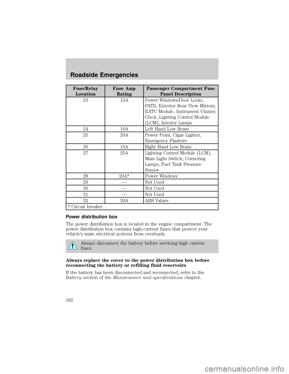
Fuse/Relay
LocationFuse Amp
RatingPassenger Compartment Fuse
Panel Description
23 15A Power Windows/Door Locks,
PATS, Exterior Rear View Mirrors,
EATC Module, Instrument Cluster,
Clock, Lighting Control Module
(LCM), Interior Lamps
24 10A Left Hand Low Beam
25 20A Power Point, Cigar Lighter,
Emergency Flashers
26 10A Right Hand Low Beam
27 25A Lighting Control Module (LCM),
Main Light Switch, Cornering
Lamps, Fuel Tank Pressure
Sensor
28 20A* Power Windows
29 Ð Not Used
30 Ð Not Used
31 Ð Not Used
32 20A ABS Values
* Circuit breaker
Power distribution box
The power distribution box is located in the engine compartment. The
power distribution box contains high-current fuses that protect your
vehicle's main electrical systems from overloads.
Always disconnect the battery before servicing high current
fuses.
Always replace the cover to the power distribution box before
reconnecting the battery or refilling fluid reservoirs
If the battery has been disconnected and reconnected, refer to the
Batterysection of theMaintenance and specificationschapter.
Roadside Emergencies
162
Page 188 of 240
CLEANING THE INSTRUMENT PANEL
Clean the instrument panel with a damp cloth, then dry with a dry cloth.
Avoid cleaners or polish that increase the gloss of the upper portion of
the instrument panel. The dull finish in this area helps protect the driver
from undesirable windshield reflection.
Your vehicle is designed with painted controls and features which
are particularly sensitive to certain products such as insect
repellent and suntan lotion. When operating the various features
on your vehicle, be certain to wash or wipe your hands clean if
you have been in contact with any of these types of products in
order to avoid possible damage to the painted surfaces.
Do not use chemical solvents or strong detergents when cleaning
the steering wheel or instrument panel to avoid contamination of
the air bag system.
Cleaning the instrument cluster lens
Wipe the cluster area with a soft, damp cotton towel. Dry the area with a
clean, dry towel.
CLEANING SEATS EQUIPPED WITH SIDE AIR BAGS
Remove dust and loose dirt with a vacuum cleaner. In order to remove
stains and soil, clean with Extra Strength Upholstery Cleaner
(E8AZ-19523±AA).
Never saturate the seat covers with any cleaning solution.
Do not use chemical solvents or strong detergents when cleaning
the seat where the side air bag is mounted. Such products could
contaminate the side air bag system and affect performance of the side
air bag in a collision. The air bag may not function correctly and not
provide injury reduction benefits.
CLEANING THE INTERIOR FABRIC, CARPETS AND CLOTH SEATS
Remove dust and loose dirt with a vacuum cleaner. Remove light stains
and soil with Extra Strength Upholstery Cleaner (E8AZ-19523±AA).
Never saturate the seat covers with cleaning solution.
Do not use household cleaning products or glass cleaners, which
can stain and discolor the fabric and affect the flame retardant
abilities of the seat materials.
Cleaning
188