2002 FIAT DUCATO 244 window
[x] Cancel search: windowPage 24 of 246
CONNECT Nav
23
IMPORTANTStarting the engine
when the modem function is on, will
cause the connection drop with data
loss as a consequence. Stooping the
engine has no effect on data transmis-
sion since the CONNECT Nav will
stay on for other 20 minutes. If a GSM
communication is in progress the sys-
tem will automatically activate a new
window for other 20 minutes. Long
GSM communications (with data
transmission) can run down the vehi-
cle battery.
Operation requirements
The modem function is operational
if the following conditions are present:
– CONNECT Nav system on;
– SIM card inserted;
– sufficient credit;
– GSM coverage.Portable computer setting
SERIAL PORT SETTING
The computer serial port shall be set
for 9600bps data transmission speed.
For “Windows 95” proceed as fol-
lows:
– open “computer resources”
– open “control panel”
– open “system”
– open “peripheral control”
– select “com and LPT ports”
– select “COM1 port”
– select “port setting”
– check: bit per second = 9600
data bit = 8
parity = no parity
stop bit = 1
flow control = Xon/Xoff
MODEM SETTING
The portable computer shall have the
modem. For “Windows 95” proceed
as follows:
– open “computer resources”
– open “control panel”
– open “modem”:
select add
select “modem types” = other
select “next” and follow the dis-
played instructions.
Page 31 of 246
CONNECT Nav
30
RADIO MODE
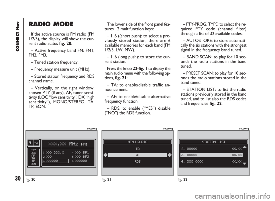
If the active source is FM radio (FM
1/2/3), the display will show the cur-
rent radio status fig. 20:
– Active frequency band FM: FM1,
FM2, FM3.
– Tuned station frequency.
– Frequency measure unit (MHz).
– Stored station frequency and RDS
channel name.
– Vertically, on the right window:
chosen PTY (if any), AF, tuner sensi-
tivity (LOC “low sensitivity”, DX “high
sensitivity”), MONO/STEREO, TA,
TP, EON.The lower side of the front panel fea-
tures 12 multifunction keys:
– 1..6 ((short push): to select a pre-
viously stored station; there are 6
available memories for each band (FM
1/2/3, LW, MW).
– 1..6 (long push): to store the cur-
rent station.
Press the knob 22-fig. 1to display the
main audio menu with the following op-
tions, fig. 21:
– TA: to enable/disable traffic an-
nouncement.
– AF: to enable/disable alternative
frequency function.
– RDS: to enable (“YES”) disable
(“NO”) the RDS function.– PTY-PROG. TYPE: to select the re-
quired PTY code (channel filter)
through a list of 32 available codes.
– AUTOSTORE: to store automati-
cally the six stations with the strongest
signal in the frequency band tuned.
– BAND SCAN: to play for 10 sec-
onds the radio stations in the band
tuned.
– PRESET SCAN: to play for 10 sec-
onds the radio stations stored in the
band tuned.
– STATION LIST: to list the radio
stations previously stored in the band
tuned, and to list also the RDS codes
and frequencies fig. 22.
fig. 20
F0D2005g
fig. 21
F0D2006g
fig. 22
F0D2007g
Page 39 of 246
CONNECT Nav
38
“BAND SCAN” FUNCTION
The “BAND SCAN” function acti-
vates station scanning in the chosen
frequency band. Each station frequen-
cy will be displayed for about 10 sec-
onds.
To turn on the “BAND SCAN” func-
tion, select and confirm “BAND
SCAN” with the knob 22-fig. 1from
the main audio menu.
During scanning, the display will
show “BAND SCAN”.
To stop the band scan function, press
“ESC” 23-fig. 1.“PRESET SCAN” FUNCTION
The “PRESET SCAN” function acti-
vates stored station scanning in the
chosen frequency band. Each stored
station will be played for about 10 sec-
onds.
To turn on the “PRESET SCAN”
function, select and confirm “PRESET
SCAN” with the knob 22-fig. 1, from
the main audio menu.
During scanning, the display will show
“PRES. SCAN”. To stop the band scan
function, press “ESC” 23-fig. 1.
“STATION LIST” FUNCTION
The “STATION LIST” function dis-
plays a screen fig. 22, listing the ra-
dio stations previously stored in the
tuned band, the RDS codes and the
corresponding frequencies.
To turn this function on, select and
confirm “STATION LIST” with the
knob 22-fig. 1from the main audio
menu. To scroll the stored station list
use the encoder 14-fig. 1.“RADIO SETUP” FUNCTION
To turn this function on, select and
confirm “RADIO SETUP” with the
knob 22-fig. 1from the main audio
menu.
This function enables to go to next
window to adjust radio settings. When
in this window it is not possible to
change the audio source. The follow-
ing functions are displayed:
– LOC/DX
– MONO/STEREO
– REGIONAL
– NEWS.
Page 55 of 246
CONNECT Nav
54
Pressing the knob 22-fig. 1will dis-
play the following options fig. 39 -
fig. 40:
– AUDIO SETUP
– DEFINE PLAYLIST
– PLAYLIST
– VIEW PLAYLIST
– COMPRESSION
– TA
– SCAN
– SHUFFLE
– REPEATTo stop the MP3 CD, press briefly II˙
10-fig. 1. To restart playing, press briefly
again II˙10-fig. 1. To pause the MP3
CD, press continuously II˙10-fig. 1.
“Stop” and “Pause” cause the stop of
track playing, maintaining in the main
screen information about the last played
song.
To eject MP3 CD 28-fig. 1press ˚
26-fig. 1.
“AUDIO SETUP” FUNCTION
(AUDIO ADJUSTMENTS)
To access the audio setup menu
while listening to a MP3 CD, select and
confirm “AUDIO SETUP” rotating and
pressing the knob 22-fig. 1.
For the description of the different
functions available in the menu, see the
corresponding paragraph in chapter
“AUDIO SETTINGS”.“DEFINE PLAYLIST”
FUNCTION
“DEFINE PLAYLIST” function allows
the management of max. 100 music
pieces among those included in the
MP3 CD, to be played in a specified se-
quence. Dedicated windows allow the
tracks choice, addition or cancellation.
It is possible to add a single track or
an entire directory. This function is de-
scribed in detail in a specific paragraph
below.
“DEFINE PLAYLIST” is disabled when
a MP3 CD is playing, you must stop CD
playing to enable it.
“PLAYLIST” FUNCTION
This function enables or disables
playback of the user track list previ-
ously programmed through the “DE-
FINE PLAYLIST” function. To turn this
function on/off, select and confirm
“PLAYLIST” rotating and pressing the
knob 22-fig. 1.
Page 64 of 246

CONNECT Nav
63
ENTERING THE PIN CODE
IMPORTANT The PIN code (Per-
sonal Identification Number) prevents
unauthorised use of SIM card services.
PIN is asked by the CONNECT sys-
tem in the following cases:
– When the system is switched on,
with SIM card already inserted into the
SIM reader and PIN lock is enabled on
that SIM card.
– When a SIM card is inserted into
the SIM reader, and the system is al-
ready on, and PIN lock is enabled on
that SIM card.
– When “TEL” button 19-fig. 1is
pushed to switch on a previously
switched off telephone module (TEL
OFF), and the SIM card is inserted into
the SIM reader, the PIN lock is enabled
on that SIM card and PIN code has nev-
er been inserted before.
– When the user tries to make a
non-emergency call and the SIM card
is inserted into the SIM reader, PIN
lock is enabled on that SIM card and
PIN code has never been inserted be-
fore.To enter the PIN code (between 4
and 8 digits) use keys 1 ÷ 12-fig. 1and
then press the knob 22-fig. 1to con-
firm. Entered digits are shown by as-
terisks on the display.
If a PIN code digit needs to be cor-
rected, press “ESC” 23-fig. 1to delete
it and write it again correctly.
IMPORTANT if the user refuses to
insert PIN, a dialog box is displayed,
saying that telephone functions will not
be available till the insertion of the cor-
rect PIN. Only emergency calls (like
police or S.O.S., etc...) will always be
enabled; in this case only input box will
be available on the display.
IMPORTANTafter the max. num-
ber of unsuccessful PIN code entries,
the card is locked. To unlock the card,
enter both the PUK code (Pin Un-
blocking Key) and the new PIN.
The network signal search begins af-
ter entering the PIN code and the dis-
play shows the main telephone func-
tion page. After connection, the display
shows the network provider’s name.INCOMING CALLS
Whichever is the system active
mode, when an external telephone call
comes in, a dialog box will be over-
lapped fig. 50on the current window
that shows the following information:
– Call from;
– Name of the calling party (if avail-
able in the directory);
– Caller phone number, if this service
is available from the network provider;
fig. 50
F0D2034g
Page 76 of 246
CONNECT Nav
75
Should the screen size be not enough
to show the entire card contents, ro-
tate the knob 22-fig. 1to scroll the
screen; the display will show arrow
“
▲” or “▼” according to the required
direction.
Rotate and press the knob 22-fig. 1
to select and confirm “MENU”, the fol-
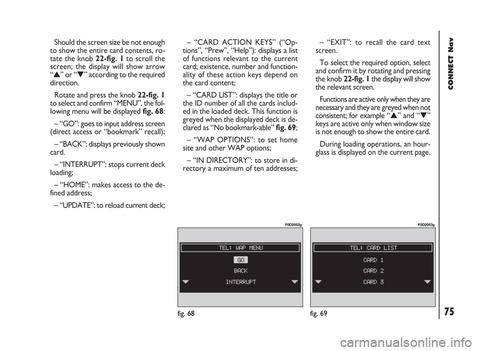
lowing menu will be displayed fig. 68:
– “GO”: goes to input address screen
(direct access or “bookmark” recall);
– “BACK”: displays previously shown
card.
– “INTERRUPT”: stops current deck
loading;
– “HOME”: makes access to the de-
fined address;
– “UPDATE”: to reload current deck;– “CARD ACTION KEYS” (“Op-
tions”, “Prew”, “Help”): displays a list
of functions relevant to the current
card; existence, number and function-
ality of these action keys depend on
the card content;
– “CARD LIST”: displays the title or
the ID number of all the cards includ-
ed in the loaded deck. This function is
greyed when the displayed deck is de-
clared as “No bookmark-able” fig. 69;
– “WAP OPTIONS”: to set home
site and other WAP options;
– “IN DIRECTORY”: to store in di-
rectory a maximum of ten addresses;– “EXIT”: to recall the card text
screen.
To select the required option, select
and confirm it by rotating and pressing
the knob 22-fig. 1the display will show
the relevant screen.
Functions are active only when they are
necessary and they are greyed when not
consistent; for example “
▲” and “▼”
keys are active only when window size
is not enough to show the entire card.
During loading operations, an hour-
glass is displayed on the current page.
fig. 68
F0D2052g
fig. 69
F0D2053g
Page 134 of 246
CONNECT Nav
133
Selecting “USE POINT” with the knob
22-fig. 1and pressing it to confirm, the
geographical coordinates can be used
to set the Navigation function or can
be entered in the navigation directory
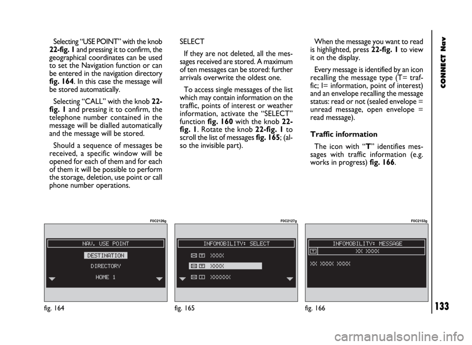
fig. 164. In this case the message will
be stored automatically.
Selecting “CALL” with the knob 22-
fig. 1and pressing it to confirm, the
telephone number contained in the
message will be dialled automatically
and the message will be stored.
Should a sequence of messages be
received, a specific window will be
opened for each of them and for each
of them it will be possible to perform
the storage, deletion, use point or call
phone number operations.
fig. 164
F0C2126g
SELECT
If they are not deleted, all the mes-
sages received are stored. A maximum
of ten messages can be stored: further
arrivals overwrite the oldest one.
To access single messages of the list
which may contain information on the
traffic, points of interest or weather
information, activate the “SELECT”
function fig. 160with the knob 22-
fig. 1. Rotate the knob 22-fig. 1to
scroll the list of messages fig. 165; (al-
so the invisible part).When the message you want to read
is highlighted, press 22-fig. 1to view
it on the display.
Every message is identified by an icon
recalling the message type (T= traf-
fic; I= information, point of interest)
and an envelope recalling the message
status: read or not (sealed envelope =
unread message, open envelope =
read message).
Traffic information
The icon with “T” identifies mes-
sages with traffic information (e.g.
works in progress) fig. 166.
fig. 165
F0C2127g
fig. 166
F0C2153g
Page 169 of 246

CONNECT Nav+
168
IMPORTANTStarting the engine
when the modem function is on, will
cause the connection drop with data
loss as a consequence. Stooping the
engine has no effect on data transmis-
sion since the CONNECT Nav+ will
stay on for other 20 minutes. If a GSM
communication is in progress the sys-
tem will automatically activate a new
window for other 20 minutes. Long
GSM communications (with data
transmission) can run down the vehi-
cle battery.
Operation requirements
The modem function is operational
if the following conditions are present:
– CONNECT Nav+ on;
– SIM card inserted;
– sufficient credit;
– GSM coverage.Portable computer setting
SERIAL PORT SETTING
The computer serial port shall be set
for 9600bps data transmission speed.
For “Windows 95” proceed as fol-
lows:
– open “computer resources”
– open “control panel”
– open “system”
– open “peripheral control”
– select “com and LPT ports”
– select “COM1 communications
port”
– select “port setting”
– check: bit per second = 9600
data bit = 8
parity = no parity
stop bit = 1
flow control = Xon/Xoff
MODEM SETTING
The portable computer shall have the
modem. For “Windows 95” proceed
as follows:
– open “computer resources”
– open “control panel”
– open “modem”:
select add
select “modem types” = other
select “next” and follow the dis-
played instructions.