2002 DODGE RAM oil pressure
[x] Cancel search: oil pressurePage 937 of 2255

Component Page
Clutch Pedal Position Switch (M/T)..... 8W-80-35
Controller Antilock Brake C1.......... 8W-80-35
Controller Antilock Brake C2 (ABS)..... 8W-80-35
Crankshaft Position Sensor (Gas 8.0L) . . . 8W-80-36
Crankshaft Position Sensor
(Gas Except 8.0L)................. 8W-80-36
Cummins Bus (Diesel)............... 8W-80-36
Cup Holder Lamp................... 8W-80-36
Data Link Connector................. 8W-80-36
Daytime Running Lamp Module........ 8W-80-37
Dome Lamp....................... 8W-80-37
Driver Airbag...................... 8W-80-37
Driver Cylinder Lock Switch........... 8W-80-37
Driver Door Ajar Switch (Base)......... 8W-80-38
Driver Door Ajar Switch (Premium)..... 8W-80-38
Driver Door Lock Motor.............. 8W-80-38
Driver Door Window/Lock Switch....... 8W-80-38
Driver Heated Seat Cushion........... 8W-80-38
Driver Heated Seat Switch............ 8W-80-39
Driver Lumbar Motor................ 8W-80-39
Driver Power Seat Front Vertical Motor
(Club Cab)....................... 8W-80-39
Driver Power Seat Front Vertical Motor
(Standard Cab)................... 8W-80-39
Driver Power Seat Horizontal Motor
(Club Cab)....................... 8W-80-39
Driver Power Seat Horizontal Motor
(Standard Cab)................... 8W-80-40
Driver Power Seat Rear Vertical Motor
(Club Cab)....................... 8W-80-40
Driver Power Seat Rear Vertical Motor
(Standard Cab)................... 8W-80-40
Driver Power Seat Switch (Club Cab).... 8W-80-40
Driver Power Seat Switch
(Standard Cab)................... 8W-80-41
Driver Power Window Motor........... 8W-80-41
Electric Brake Provision.............. 8W-80-41
Engine Control Module (Diesel)........ 8W-80-41
Engine Coolant Temperature Sensor
(Diesel)......................... 8W-80-42
Engine Coolant Temperature Sensor
(Gas)........................... 8W-80-43
Engine Oil Pressure Sensor (Diesel)..... 8W-80-43
Engine Oil Pressure Sensor (Gas)....... 8W-80-43
EVAP/Purge Solenoid................ 8W-80-43
Front Washer Pump................. 8W-80-43
Fuel Heater (Diesel)................. 8W-80-43
Fuel Injection Pump (Diesel)........... 8W-80-44
Fuel Injector No. 1.................. 8W-80-44
Fuel Injector No. 2.................. 8W-80-44
Fuel Injector No. 3.................. 8W-80-44
Fuel Injector No. 4.................. 8W-80-44
Fuel Injector No. 5.................. 8W-80-45
Fuel Injector No. 6.................. 8W-80-45
Fuel Injector No. 7 (5.2L/5.9L/8.0L)..... 8W-80-45Component Page
Fuel Injector No. 8 (5.2L/5.9L/8.0L)..... 8W-80-45
Fuel Injector No. 9 (8.0L)............. 8W-80-45
Fuel Injector No. 10 (8.0L)............ 8W-80-46
Fuel Pump Module (Gas)............. 8W-80-46
Fuel Tank Module (Diesel)............ 8W-80-46
Fuel Transfer Pump (Diesel)........... 8W-80-46
G300............................. 8W-80-46
Generator......................... 8W-80-47
Glove Box Lamp And Switch........... 8W-80-47
Headlamp Switch C1................ 8W-80-47
Headlamp Switch C2................ 8W-80-47
Heated Mirror Switch................ 8W-80-48
High Note Horn.................... 8W-80-48
Idle Air Control Motor................ 8W-80-48
Ignition Coil (3.9L/5.2L/5.9L).......... 8W-80-48
Ignition Coil 4 Pack (8.0L)............ 8W-80-48
Ignition Coil 6 Pack (8.0L)............ 8W-80-49
Ignition Switch C1.................. 8W-80-49
Ignition Switch C2.................. 8W-80-49
Instrument Cluster C1............... 8W-80-49
Instrument Cluster C2............... 8W-80-50
Intake Air Heater Relays (Diesel)....... 8W-80-50
Intake Air Temperature Sensor (Diesel) . . 8W-80-50
Intake Air Temperature Sensor (Gas).... 8W-80-50
Joint Connector No. 1 (In PDC)........ 8W-80-50
Joint Connector No. 2 (In PDC)........ 8W-80-51
Joint Connector No. 5................ 8W-80-52
Joint Connector No. 6................ 8W-80-52
Joint Connector No. 7................ 8W-80-53
Joint Connector No. 8................ 8W-80-53
Junction Block C1................... 8W-80-54
Junction Block C2................... 8W-80-54
Junction Block C3................... 8W-80-54
Junction Block C4................... 8W-80-55
Junction Block C5................... 8W-80-55
Junction Block C6................... 8W-80-55
Junction Block C7................... 8W-80-55
Junction Block C8................... 8W-80-56
Junction Block C9................... 8W-80-56
Leak Detection Pump (Gas)........... 8W-80-56
Left Back-Up Lamp.................. 8W-80-57
Left Fog Lamp..................... 8W-80-57
Left Front Door Speaker (Premium)..... 8W-80-57
Left Front Door Speaker (Standard)..... 8W-80-57
Left Front Fender Lamp
(Dual Rear Wheels)................ 8W-80-57
Left Front Wheel Speed Sensor (ABS) . . . 8W-80-58
Left Headlamp..................... 8W-80-58
Left License Lamp.................. 8W-80-58
Left Outboard Clearance Lamp......... 8W-80-58
Left Outboard Headlamp............. 8W-80-58
Left Outboard Identification Lamp...... 8W-80-59
Left Park/Turn Signal Lamp........... 8W-80-59
Left Power Mirror................... 8W-80-59
8W - 80 - 2 8W-80 CONNECTOR PIN-OUTSBR/BE
Page 976 of 2255

DRIVER POWER SEAT SWITCH (STANDARD CAB) - 14 WAY
CAV CIRCUIT FUNCTION
A F37 14RD/LB FUSED B(+)
B Z3 14BK/OR GROUND
C- -
D- -
E P11 14YL/WT LEFT SEAT REAR UP
F- -
G- -
H- -
I- -
J P13 14RD/WT LEFT SEAT REAR DOWN
K P17 14DB/RD LEFT SEAT HORIZONTAL REARWARD
L P15 14YL/LB LEFT SEAT HORIZONTAL FORWARD
M P19 14YL/LG LEFT SEAT FRONT UP
N P21 14RD/LG LEFT SEAT FRONT DOWN
DRIVER POWER WINDOW MOTOR-2WAY
CAV CIRCUIT FUNCTION
1 Q11 16LB LEFT WINDOW DRIVER (UP)
2 Q21 16WT LEFT FRONT WINDOW DRIVER (DOWN)
ELECTRIC BRAKE PROVISION-4WAY
CAV CIRCUIT FUNCTION
1 A6 12RD/OR FUSED B(+)
2 B40 12LB TRAILER TOW BRAKE B(+)
3 L50 18WT/TN BRAKE LAMP SWITCH OUTPUT
4 Z3 18BK/OR GROUND
ENGINE CONTROL MODULE (DIESEL) - 50 WAY
CAV CIRCUIT FUNCTION
1 H104 18BR/OR IDLE VALIDATION SWITCH NO. 1
2 K244 20YL/DB CUMMINS BUS (+)
3 K6 18VT/WT 5V SUPPLY
4 K14 18BK/DB SENSOR GROUND
5 F18 18LG/BK FUSED IGNITION SWITCH OUTPUT (RUN-START)
6 G60 18GY/BK ENGINE OIL PRESSURE SENSOR SIGNAL
7 K21 18BK/RD INTAKE AIR TEMPERATURE SENSOR SIGNAL
8 G12 18GY/RD MANIFOLD ABSOLUTE PRESSURE SENSOR SIGNAL
9- -
10 K7 18OR 5V SUPPLY
11 K104 18BK/LB SENSOR GROUND
BR/BE8W-80 CONNECTOR PIN-OUTS 8W - 80 - 41
Page 978 of 2255
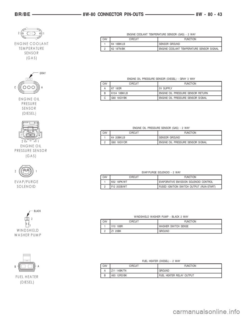
ENGINE COOLANT TEMPERATURE SENSOR (GAS)-2WAY
CAV CIRCUIT FUNCTION
1 K4 18BK/LB SENSOR GROUND
2 K2 18TN/BK ENGINE COOLANT TEMPERATURE SENSOR SIGNAL
ENGINE OIL PRESSURE SENSOR (DIESEL) - GRAY 3 WAY
CAV CIRCUIT FUNCTION
A K7 18OR 5V SUPPLY
B K104 18BK/LB ENGINE OIL PRESSURE SENSOR RETURN
C G60 18GY/BK ENGINE OIL PRESSURE SENSOR SIGNAL
ENGINE OIL PRESSURE SENSOR (GAS)-2WAY
CAV CIRCUIT FUNCTION
1 K4 20BK/LB SENSOR GROUND
2 G60 18GY/OR ENGINE OIL PRESSURE SENSOR SIGNAL
EVAP/PURGE SOLENOID-2WAY
CAV CIRCUIT FUNCTION
1 K52 18PK/WT EVAPORATIVE EMISSION SOLENOID CONTROL
2 F12 20DB/WT FUSED IGNITION SWITCH OUTPUT (RUN-START)
WINDSHIELD WASHER PUMP - BLACK 2 WAY
CAV CIRCUIT FUNCTION
1 V10 16BR WASHER SWITCH SENSE
2 Z1 20BK GROUND
FUEL HEATER (DIESEL)-2WAY
CAV CIRCUIT FUNCTION
A Z11 14BK/TN GROUND
B A93 12RD/BK FUEL HEATER RELAY OUTPUT
BR/BE8W-80 CONNECTOR PIN-OUTS 8W - 80 - 43
Page 1007 of 2255
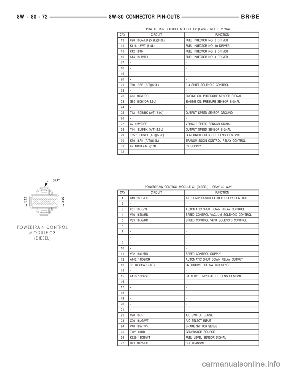
POWERTRAIN CONTROL MODULE C2 (GAS) - WHITE 32 WAY
CAV CIRCUIT FUNCTION
13 K28 18GY/LB (5.9L)(8.0L) FUEL INJECTOR NO. 8 DRIVER
14 K116 18WT (8.0L) FUEL INJECTOR NO. 10 DRIVER
15 K12 18TN FUEL INJECTOR NO. 2 DRIVER
16 K14 18LB/BR FUEL INJECTOR NO. 4 DRIVER
17 - -
18 - -
19 - -
20 - -
21 T60 18BR (A/T)(5.9L) 3-4 SHIFT SOLENOID CONTROL
22 - -
23 G60 18GY/OR ENGINE OIL PRESSURE SENSOR SIGNAL
23 G60 18GY/OR(5.9L) ENGINE OIL PRESURE SENSOR SIGNAL
24 - -
25 T13 18DB/BK (A/T)(5.9L) OUTPUT SPEED SENSOR GROUND
26 - -
27 G7 18WT/OR VEHICLE SPEED SENSOR SIGNAL
28 T14 18LG/BK (A/T)(5.9L) OUTPUT SPEED SENSOR SIGNAL
29 T25 18LG/WT (A/T)(5.9L) GOVERNOR PRESSURE SENSOR SIGNAL
30 K30 18PK (A/T)(5.9L) TRANSMISSION CONTROL RELAY CONTROL
31 K7 18OR (A/T)(5.9L) 5V SUPPLY
32 - -
POWERTRAIN CONTROL MODULE C3 (DIESEL) - GRAY 32 WAY
CAV CIRCUIT FUNCTION
1 C13 18DB/OR A/C COMPRESSOR CLUTCH RELAY CONTROL
2- -
3 K51 18DB/YL AUTOMATIC SHUT DOWN RELAY CONTROL
4 V36 18TN/RD SPEED CONTROL VACUUM SOLENOID CONTROL
5 V35 18LG/RD SPEED CONTROL VENT SOLENOID CONTROL
6- -
7- -
8- -
9- -
10 - -
11 V32 18YL/RD SPEED CONTROL SUPPLY
12 A142 14DG/OR AUTOMATIC SHUT DOWN RELAY OUTPUT
13 T6 18OR/WT (A/T) OVERDRIVE OFF SWITCH SENSE
14 - -
15 K118 18PK/YL BATTERY TEMPERATURE SENSOR SIGNAL
16 - -
17 - -
18 - -
19 - -
20 - -
21 - -
22 C20 18BR A/C SWITCH SENSE
23 C90 18LG/WT A/C SELECT INPUT
24 V40 18WT/PK BRAKE SWITCH SENSE
25 T125 18DB GENERATOR SOURCE
26 K226 18DB/WT FUEL LEVEL SENSOR SIGNAL
27 D21 18PK/DB SCI TRANSMIT
8W - 80 - 72 8W-80 CONNECTOR PIN-OUTSBR/BE
Page 1021 of 2255
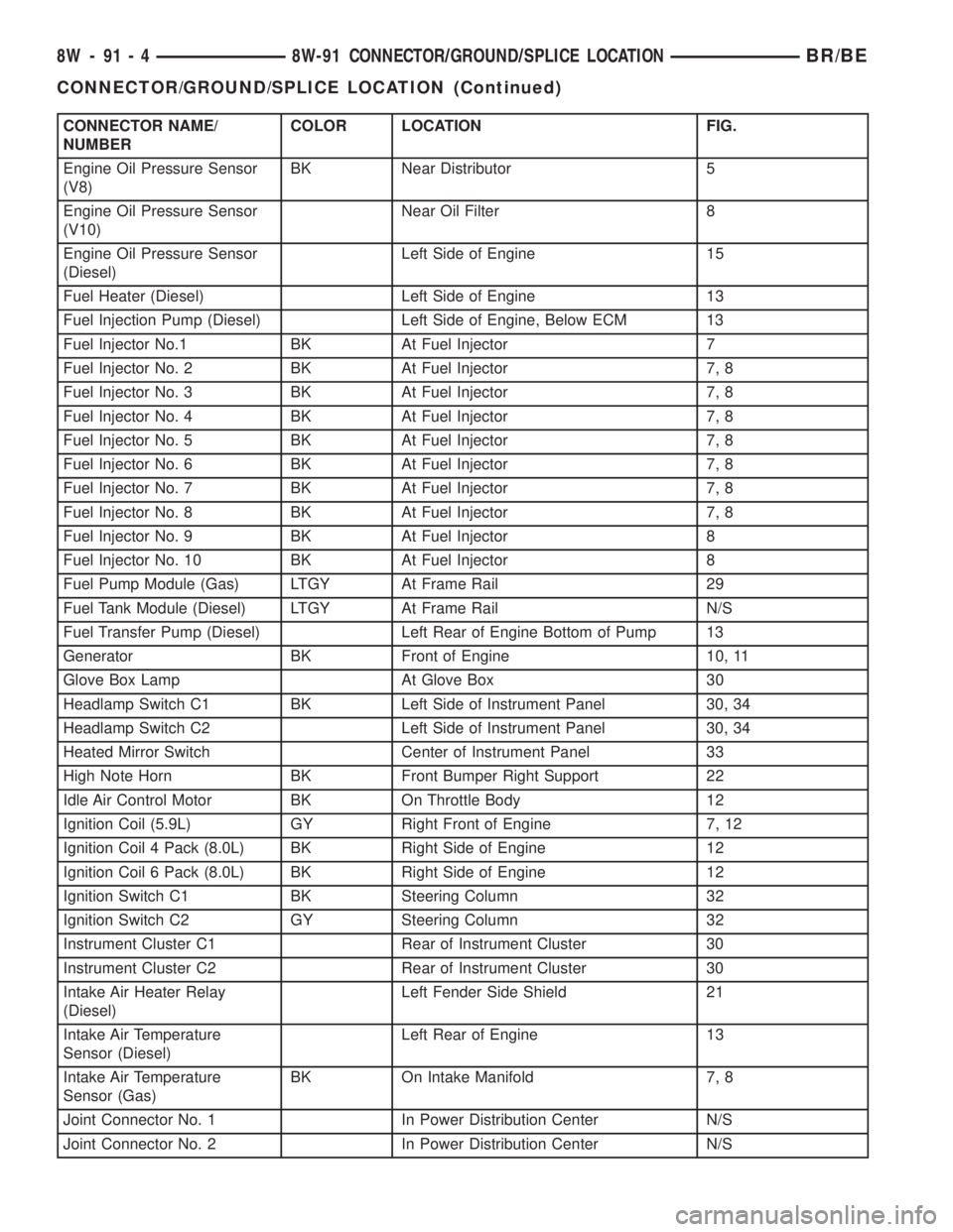
CONNECTOR NAME/
NUMBERCOLOR LOCATION FIG.
Engine Oil Pressure Sensor
(V8)BK Near Distributor 5
Engine Oil Pressure Sensor
(V10)Near Oil Filter 8
Engine Oil Pressure Sensor
(Diesel)Left Side of Engine 15
Fuel Heater (Diesel) Left Side of Engine 13
Fuel Injection Pump (Diesel) Left Side of Engine, Below ECM 13
Fuel Injector No.1 BK At Fuel Injector 7
Fuel Injector No. 2 BK At Fuel Injector 7, 8
Fuel Injector No. 3 BK At Fuel Injector 7, 8
Fuel Injector No. 4 BK At Fuel Injector 7, 8
Fuel Injector No. 5 BK At Fuel Injector 7, 8
Fuel Injector No. 6 BK At Fuel Injector 7, 8
Fuel Injector No. 7 BK At Fuel Injector 7, 8
Fuel Injector No. 8 BK At Fuel Injector 7, 8
Fuel Injector No. 9 BK At Fuel Injector 8
Fuel Injector No. 10 BK At Fuel Injector 8
Fuel Pump Module (Gas) LTGY At Frame Rail 29
Fuel Tank Module (Diesel) LTGY At Frame Rail N/S
Fuel Transfer Pump (Diesel) Left Rear of Engine Bottom of Pump 13
Generator BK Front of Engine 10, 11
Glove Box Lamp At Glove Box 30
Headlamp Switch C1 BK Left Side of Instrument Panel 30, 34
Headlamp Switch C2 Left Side of Instrument Panel 30, 34
Heated Mirror Switch Center of Instrument Panel 33
High Note Horn BK Front Bumper Right Support 22
Idle Air Control Motor BK On Throttle Body 12
Ignition Coil (5.9L) GY Right Front of Engine 7, 12
Ignition Coil 4 Pack (8.0L) BK Right Side of Engine 12
Ignition Coil 6 Pack (8.0L) BK Right Side of Engine 12
Ignition Switch C1 BK Steering Column 32
Ignition Switch C2 GY Steering Column 32
Instrument Cluster C1 Rear of Instrument Cluster 30
Instrument Cluster C2 Rear of Instrument Cluster 30
Intake Air Heater Relay
(Diesel)Left Fender Side Shield 21
Intake Air Temperature
Sensor (Diesel)Left Rear of Engine 13
Intake Air Temperature
Sensor (Gas)BK On Intake Manifold 7, 8
Joint Connector No. 1 In Power Distribution Center N/S
Joint Connector No. 2 In Power Distribution Center N/S
8W - 91 - 4 8W-91 CONNECTOR/GROUND/SPLICE LOCATIONBR/BE
CONNECTOR/GROUND/SPLICE LOCATION (Continued)
Page 1026 of 2255
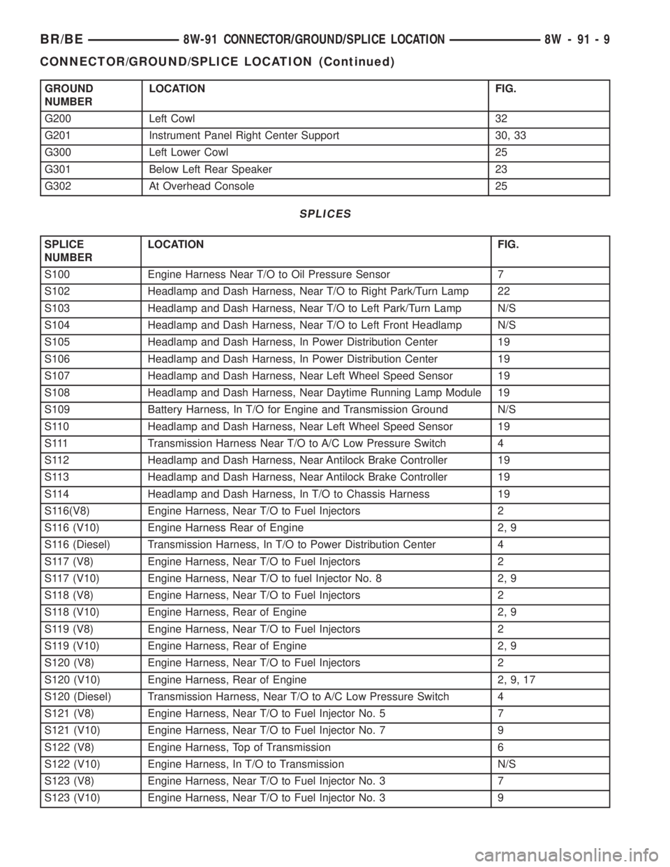
GROUND
NUMBERLOCATION FIG.
G200 Left Cowl 32
G201 Instrument Panel Right Center Support 30, 33
G300 Left Lower Cowl 25
G301 Below Left Rear Speaker 23
G302 At Overhead Console 25
SPLICES
SPLICE
NUMBERLOCATION FIG.
S100 Engine Harness Near T/O to Oil Pressure Sensor 7
S102 Headlamp and Dash Harness, Near T/O to Right Park/Turn Lamp 22
S103 Headlamp and Dash Harness, Near T/O to Left Park/Turn Lamp N/S
S104 Headlamp and Dash Harness, Near T/O to Left Front Headlamp N/S
S105 Headlamp and Dash Harness, In Power Distribution Center 19
S106 Headlamp and Dash Harness, In Power Distribution Center 19
S107 Headlamp and Dash Harness, Near Left Wheel Speed Sensor 19
S108 Headlamp and Dash Harness, Near Daytime Running Lamp Module 19
S109 Battery Harness, In T/O for Engine and Transmission Ground N/S
S110 Headlamp and Dash Harness, Near Left Wheel Speed Sensor 19
S111 Transmission Harness Near T/O to A/C Low Pressure Switch 4
S112 Headlamp and Dash Harness, Near Antilock Brake Controller 19
S113 Headlamp and Dash Harness, Near Antilock Brake Controller 19
S114 Headlamp and Dash Harness, In T/O to Chassis Harness 19
S116(V8) Engine Harness, Near T/O to Fuel Injectors 2
S116 (V10) Engine Harness Rear of Engine 2, 9
S116 (Diesel) Transmission Harness, In T/O to Power Distribution Center 4
S117 (V8) Engine Harness, Near T/O to Fuel Injectors 2
S117 (V10) Engine Harness, Near T/O to fuel Injector No. 8 2, 9
S118 (V8) Engine Harness, Near T/O to Fuel Injectors 2
S118 (V10) Engine Harness, Rear of Engine 2, 9
S119 (V8) Engine Harness, Near T/O to Fuel Injectors 2
S119 (V10) Engine Harness, Rear of Engine 2, 9
S120 (V8) Engine Harness, Near T/O to Fuel Injectors 2
S120 (V10) Engine Harness, Rear of Engine 2, 9, 17
S120 (Diesel) Transmission Harness, Near T/O to A/C Low Pressure Switch 4
S121 (V8) Engine Harness, Near T/O to Fuel Injector No. 5 7
S121 (V10) Engine Harness, Near T/O to Fuel Injector No. 7 9
S122 (V8) Engine Harness, Top of Transmission 6
S122 (V10) Engine Harness, In T/O to Transmission N/S
S123 (V8) Engine Harness, Near T/O to Fuel Injector No. 3 7
S123 (V10) Engine Harness, Near T/O to Fuel Injector No. 3 9
BR/BE8W-91 CONNECTOR/GROUND/SPLICE LOCATION 8W - 91 - 9
CONNECTOR/GROUND/SPLICE LOCATION (Continued)
Page 1027 of 2255
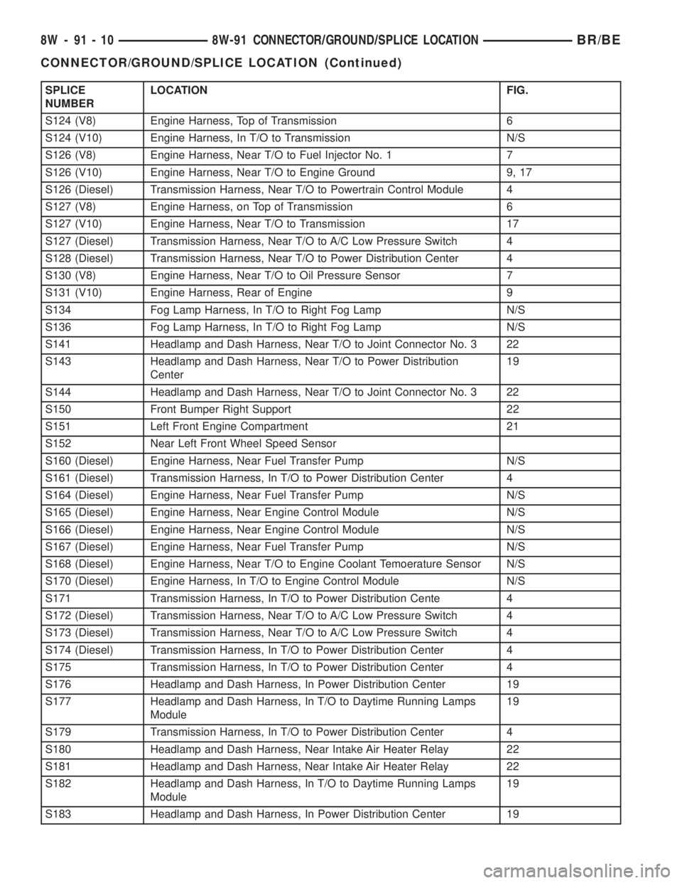
SPLICE
NUMBERLOCATION FIG.
S124 (V8) Engine Harness, Top of Transmission 6
S124 (V10) Engine Harness, In T/O to Transmission N/S
S126 (V8) Engine Harness, Near T/O to Fuel Injector No. 1 7
S126 (V10) Engine Harness, Near T/O to Engine Ground 9, 17
S126 (Diesel) Transmission Harness, Near T/O to Powertrain Control Module 4
S127 (V8) Engine Harness, on Top of Transmission 6
S127 (V10) Engine Harness, Near T/O to Transmission 17
S127 (Diesel) Transmission Harness, Near T/O to A/C Low Pressure Switch 4
S128 (Diesel) Transmission Harness, Near T/O to Power Distribution Center 4
S130 (V8) Engine Harness, Near T/O to Oil Pressure Sensor 7
S131 (V10) Engine Harness, Rear of Engine 9
S134 Fog Lamp Harness, In T/O to Right Fog Lamp N/S
S136 Fog Lamp Harness, In T/O to Right Fog Lamp N/S
S141 Headlamp and Dash Harness, Near T/O to Joint Connector No. 3 22
S143 Headlamp and Dash Harness, Near T/O to Power Distribution
Center19
S144 Headlamp and Dash Harness, Near T/O to Joint Connector No. 3 22
S150 Front Bumper Right Support 22
S151 Left Front Engine Compartment 21
S152 Near Left Front Wheel Speed Sensor
S160 (Diesel) Engine Harness, Near Fuel Transfer Pump N/S
S161 (Diesel) Transmission Harness, In T/O to Power Distribution Center 4
S164 (Diesel) Engine Harness, Near Fuel Transfer Pump N/S
S165 (Diesel) Engine Harness, Near Engine Control Module N/S
S166 (Diesel) Engine Harness, Near Engine Control Module N/S
S167 (Diesel) Engine Harness, Near Fuel Transfer Pump N/S
S168 (Diesel) Engine Harness, Near T/O to Engine Coolant Temoerature Sensor N/S
S170 (Diesel) Engine Harness, In T/O to Engine Control Module N/S
S171 Transmission Harness, In T/O to Power Distribution Cente 4
S172 (Diesel) Transmission Harness, Near T/O to A/C Low Pressure Switch 4
S173 (Diesel) Transmission Harness, Near T/O to A/C Low Pressure Switch 4
S174 (Diesel) Transmission Harness, In T/O to Power Distribution Center 4
S175 Transmission Harness, In T/O to Power Distribution Center 4
S176 Headlamp and Dash Harness, In Power Distribution Center 19
S177 Headlamp and Dash Harness, In T/O to Daytime Running Lamps
Module19
S179 Transmission Harness, In T/O to Power Distribution Center 4
S180 Headlamp and Dash Harness, Near Intake Air Heater Relay 22
S181 Headlamp and Dash Harness, Near Intake Air Heater Relay 22
S182 Headlamp and Dash Harness, In T/O to Daytime Running Lamps
Module19
S183 Headlamp and Dash Harness, In Power Distribution Center 19
8W - 91 - 10 8W-91 CONNECTOR/GROUND/SPLICE LOCATIONBR/BE
CONNECTOR/GROUND/SPLICE LOCATION (Continued)
Page 1073 of 2255
contained within a small, rectangular, molded plastic
housing and is connected to all of the required inputs
and outputs by five integral male spade-type termi-
nals that extend from the bottom of the relay base.
Relays cannot be adjusted or repaired and, if faulty
or damaged, the unit must be replaced.
OPERATION
A micro-relay is an electromechanical switch that
uses a low current input from one source to control a
high current output to another device. The movable
common feed contact point is held against the fixed
normally closed contact point by spring pressure.
When the relay coil is energized, an electromagnetic
field is produced by the coil windings. This electro-
magnetic field draws the movable relay contact point
away from the fixed normally closed contact point,
and holds it against the fixed normally open contact
point. When the relay coil is de-energized, spring
pressure returns the movable contact point back
against the fixed normally closed contact point. A
resistor is connected in parallel with the relay coil in
the relay, and helps to dissipate voltage spikes and
electromagnetic interference that can be generated as
the electromagnetic field of the relay coil collapses.
DIAGNOSIS AND TESTING - MICRO-RELAY
(1) Remove the relay from its mounting location.
(2) A relay in the de-energized position should
have continuity between terminals 87A and 30, and
no continuity between terminals 87 and 30. If OK, go
to Step 3. If not OK, replace the faulty relay.
(3) Resistance between terminals 85 and 86 (elec-
tromagnet) should be 67.5 - 82.5 ohms. If OK, go to
Step 4. If not OK, replace the faulty relay.
(4) Connect a battery to terminals 85 and 86.
There should now be continuity between terminals
30 and 87, and no continuity between terminals 87A
and 30. If OK, reinstall the relay and use a DRBIIIt
scan tool to perform further testing. Refer to the
appropriate diagnostic information.
Refer to the appropriate wiring information. The
wiring information includes wiring diagrams, proper
wire and connector repair procedures, details of wire
harness routing and retention, connector pin-out
information and location views for the various wire
harness connectors, splices and grounds.
REMOVAL
(1) Remove the relay by grasping it firmly and
pulling it straight out from its receptacle.
INSTALLATION
(1) Align the micro-relay terminals with the termi-
nal cavities in the receptacle.(2) Push firmly and evenly on the top of the relay
until the terminals are fully seated in the terminal
cavities in the receptacle.
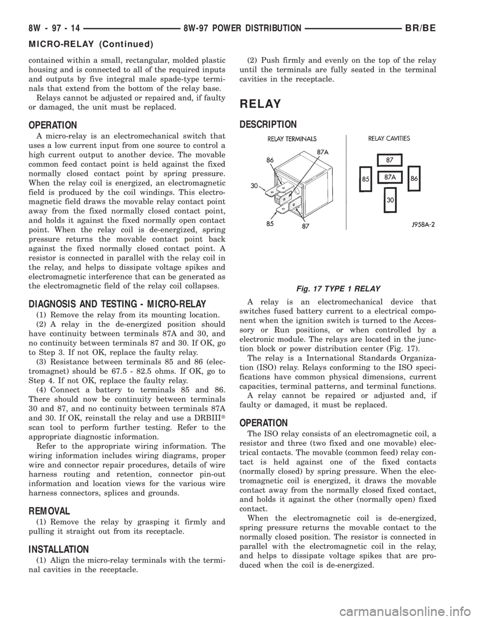
RELAY
DESCRIPTION
A relay is an electromechanical device that
switches fused battery current to a electrical compo-
nent when the ignition switch is turned to the Acces-
sory or Run positions, or when controlled by a
electronic module. The relays are located in the junc-
tion block or power distribution center (Fig. 17).
The relay is a International Standards Organiza-
tion (ISO) relay. Relays conforming to the ISO speci-
fications have common physical dimensions, current
capacities, terminal patterns, and terminal functions.
A relay cannot be repaired or adjusted and, if
faulty or damaged, it must be replaced.
OPERATION
The ISO relay consists of an electromagnetic coil, a
resistor and three (two fixed and one movable) elec-
trical contacts. The movable (common feed) relay con-
tact is held against one of the fixed contacts
(normally closed) by spring pressure. When the elec-
tromagnetic coil is energized, it draws the movable
contact away from the normally closed fixed contact,
and holds it against the other (normally open) fixed
contact.
When the electromagnetic coil is de-energized,
spring pressure returns the movable contact to the
normally closed position. The resistor is connected in
parallel with the electromagnetic coil in the relay,
and helps to dissipate voltage spikes that are pro-
duced when the coil is de-energized.
Fig. 17 TYPE 1 RELAY
8W - 97 - 14 8W-97 POWER DISTRIBUTIONBR/BE
MICRO-RELAY (Continued)