2002 DODGE RAM sensor
[x] Cancel search: sensorPage 229 of 2255

NOTE: Check the sensor wire routing. Be sure the
wire is clear of all chassis components and is not
twisted or kinked at any spot.
(6) Install the tire and wheel assembly.
(7) Remove the support and lower the vehicle.
(8) Reconnect the ABS wheel speed sensor wire
electrical connector inside the engine compartment.
(9) Apply the brakes several times to seat the
brake shoes and caliper piston. Do not move the vehi-
cle until a firm brake pedal is obtained.
(10) Verify the wheel speed sensor operation with
a scan tool.
REAR WHEEL SPEED SENSOR
DIAGNOSIS AND TESTING - REAR WHEEL
SPEED SENSOR
Diagnosis of base brake conditions which are
mechanical in nature should be performed first. This
includes brake noise, lack of power assist, parking
brake, or vehicle vibration during normal braking.
The Antilock brake system performs several self-
tests every time the ignition switch is turned on and
the vehicle is driven. The CAB monitors the system
inputs and outputs circuits to verify the system is
operating properly. If the CAB senses a malfunction
in the system it will set a DTC into memory and trig-
ger the warning lamp.
NOTE: The MDS or DRB III scan tool is used to
diagnose the Antilock Brake system. For test proce-
dures refer to the Chassis Diagnostic Manual.
REMOVAL
(1) Raise vehicle on hoist.
(2) Remove brake line mounting nut and remove
the brake line from the sensor stud.
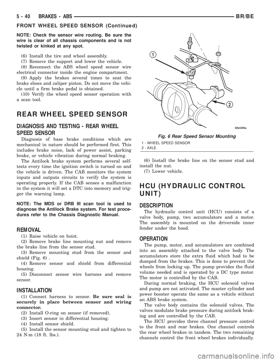
(3) Remove mounting stud from the sensor and
shield (Fig. 6) .
(4) Remove sensor and shield from differential
housing.
(5) Disconnect sensor wire harness and remove
sensor.
INSTALLATION
(1) Connect harness to sensor.Be sure seal is
securely in place between sensor and wiring
connector.
(2) Install O-ring on sensor (if removed).
(3) Insert sensor in differential housing.
(4) Install sensor shield.
(5) Install the sensor mounting stud and tighten to
24 N´m (18 ft. lbs.).(6) Install the brake line on the sensor stud and
install the nut.
(7) Lower vehicle.
HCU (HYDRAULIC CONTROL
UNIT)
DESCRIPTION
The hydraulic control unit (HCU) consists of a
valve body, pump, two accumulators and a motor.
The assembly is mounted on the driverside inner
fender under the hood.
OPERATION
The pump, motor, and accumulators are combined
into an assembly attached to the valve body. The
accumulators store the extra fluid which had to be
dumped from the brakes. This is done to prevent the
wheels from locking up. The pump provides the fluid
volume needed and is operated by a DC type motor.
The motor is controlled by the CAB.
During normal braking, the HCU solenoid valves
and pump are not activated. The master cylinder and
power booster operate the same as a vehicle without
an ABS brake system.
The valve body contains the solenoid valves. The
valves modulate brake pressure during antilock brak-
ing and are controlled by the CAB.
The HCU provides three channel pressure control
to the front and rear brakes. One channel controls
the rear wheel brakes in tandem. The two remaining
channels control the front wheel brakes individually.
Fig. 6 Rear Speed Sensor Mounting
1 - WHEEL SPEED SENSOR
2 - AXLE
5 - 40 BRAKES - ABSBR/BE
FRONT WHEEL SPEED SENSOR (Continued)
Page 230 of 2255

During antilock braking, the solenoid valves are
opened and closed as needed. The valves are not
static. They are cycled rapidly and continuously to
modulate pressure and control wheel slip and decel-
eration.
During antilock braking, solenoid valve pressure
modulation occurs in three stages, pressure decrease,
pressure hold, and pressure increase. The valves are
all contained in the valve body portion of the HCU.
PRESSURE DECREASE
The inlet valve is closed and the outlet valve is
opened during the pressure decrease cycle.
A pressure decrease cycle is initiated when speed
sensor signals indicate high wheel slip at one or
more wheels. At this point, the CAB closes the inlet
to prevent the driver from further increasing the
brake pressure and locking the brakes. The CAB
then opens the outlet valve, which also opens the
return circuit to the accumulators. Fluid pressure is
allowed to bleed off (decrease) as needed to prevent
wheel lock.
Once the period of high wheel slip has ended, the
CAB closes the outlet valve and begins a pressure
increase or hold cycle as needed.
PRESSURE HOLD
Both solenoid valves are closed in the pressure
hold cycle. Fluid apply pressure in the control chan-
nel is maintained at a constant rate. The CAB main-
tains the hold cycle until sensor inputs indicate a
pressure change is necessary.
PRESSURE INCREASE
The inlet valve is open and the outlet valve is
closed during the pressure increase cycle. The pres-
sure increase cycle is used to counteract unequal
wheel speeds. This cycle controls re-application of
fluid apply pressure due to changing road surfaces or
wheel speed.
REMOVAL
(1) Disconnect battery negative cable.
(2) Push the harness connector locks to release the
locks, then remove the connectors from the CAB.
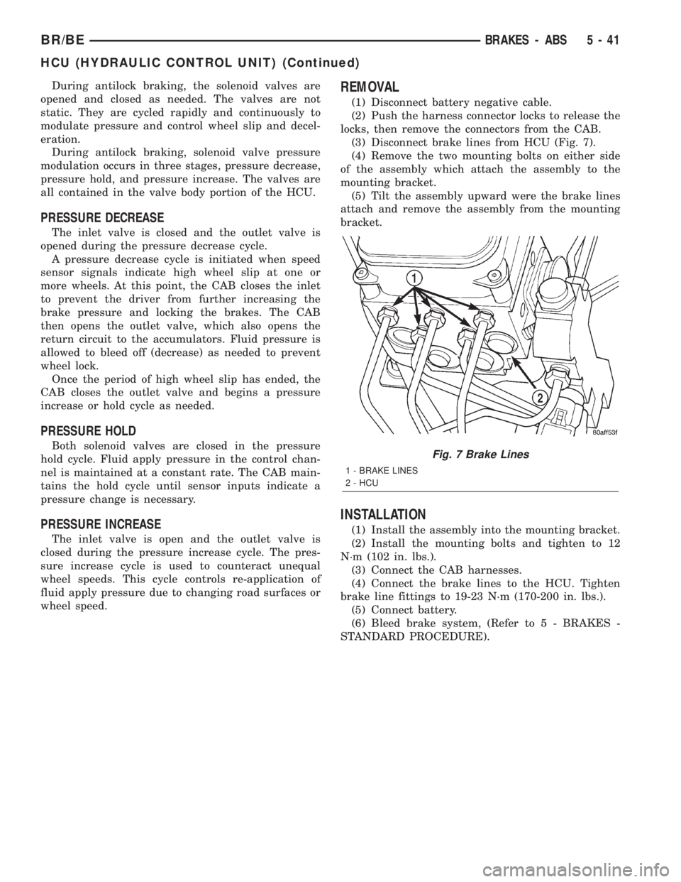
(3) Disconnect brake lines from HCU (Fig. 7).
(4) Remove the two mounting bolts on either side
of the assembly which attach the assembly to the
mounting bracket.
(5) Tilt the assembly upward were the brake lines
attach and remove the assembly from the mounting
bracket.
INSTALLATION
(1) Install the assembly into the mounting bracket.
(2) Install the mounting bolts and tighten to 12
N´m (102 in. lbs.).
(3) Connect the CAB harnesses.
(4) Connect the brake lines to the HCU. Tighten
brake line fittings to 19-23 N´m (170-200 in. lbs.).
(5) Connect battery.
(6) Bleed brake system, (Refer to 5 - BRAKES -
STANDARD PROCEDURE).
Fig. 7 Brake Lines
1 - BRAKE LINES
2 - HCU
BR/BEBRAKES - ABS 5 - 41
HCU (HYDRAULIC CONTROL UNIT) (Continued)
Page 256 of 2255

DIAGNOSIS AND TESTING - COOLING SYSTEM GAS ENGINE
COOLING SYSTEM DIAGNOSISÐGASOLINE ENGINE
CONDITION POSSIBLE CAUSES CORRECTION
TEMPERATURE GAUGE READS
LOW1. Has a Diagnostic Trouble Code
(DTC) been set indicating a stuck
open thermostat?1. (Refer to 25 - EMISSIONS
CONTROL - DESCRIPTION) for
On-Board Diagnostics and DTC
information. Replace thermostat if
necessary.
2. Is the temperature sending unit
connected?2. Check the temperature sensor
connector. (Refer to 8 -
ELECTRICAL/INSTRUMENT
CLUSTER - SCHEMATIC -
ELECTRICAL) Repair connector if
necessary.
3. Is the temperature gauge
operating OK?3. Check gauge operation. (Refer to
8 - ELECTRICAL/INSTRUMENT
CLUSTER/ENGINE
TEMPERATURE GAUGE -
DESCRIPTION). Repair as
necessary.
4. Coolant level low in cold ambient
temperatures accompanied with
poor heater performance.4. Check coolant level in the coolant
reserve/overflow tank and the
radiator. Inspect system for leaks.
Repair leaks as necessary. Refer to
the Coolant section of the manual
text for WARNINGS and
CAUTIONS associated with
removing the radiator cap.
5. Improper operation of internal
heater doors or heater controls.5. Inspect heater and repair as
necessary. (Refer to 24 - HEATING
& AIR CONDITIONING -
DIAGNOSIS AND TESTING) for
procedures.
BR/BECOOLING 7 - 7
COOLING (Continued)
Page 259 of 2255

CONDITION POSSIBLE CAUSES CORRECTION
TEMPERATURE GAUGE READING
IS INCONSISTENT (FLUCTUATES,
CYCLES OR IS ERRATIC)1. During cold weather operation,
with the heater blower in the high
position, the gauge reading may
drop slightly.1. A normal condition. No correction
is necessary.
2. Temperature gauge or engine
mounted gauge sensor defective or
shorted. Also, corroded or loose
wiring in this circuit.2. Check operation of gauge and
repair if necessary. (Refer to 8 -
ELECTRICAL/INSTRUMENT
CLUSTER - DIAGNOSIS AND
TESTING).
3. Gauge reading rises when
vehicle is brought to a stop after
heavy use (engine still running)3. A normal condition. No correction
is necessary. Gauge should return
to normal range after vehicle is
driven.
4. Gauge reading high after
re-starting a warmed up (hot)
engine.4. A normal condition. No correction
is necessary. The gauge should
return to normal range after a few
minutes of engine operation.
5. Coolant level low in radiator (air
will build up in the cooling system
causing the thermostat to open
late).5. Check and correct coolant leaks.
(Refer to 7 - COOLING -
DIAGNOSIS AND TESTING).
6. Cylinder head gasket leaking
allowing exhaust gas to enter
cooling system causing a
thermostat to open late.6. (a) Check for cylinder head
gasket leaks. (Refer to 7 -
COOLING - DIAGNOSIS AND
TESTING).
(b) Check for coolant in the engine
oil. Inspect for white steam emitting
from the exhaust system. Repair as
necessary.
7. Water pump impeller loose on
shaft.7. Check water pump and replace
as necessary. (Refer to 7 -
COOLING/ENGINE/WATER PUMP -
REMOVAL).
8. Loose accessory drive belt.
(water pump slipping)8. (Refer to 7 - COOLING/
ACCESSORY DRIVE/DRIVE BELTS
- DIAGNOSIS AND TESTING).
Check and correct as necessary.
9. Air leak on the suction side of
the water pump allows air to build
up in cooling system causing
thermostat to open late.9. Locate leak and repair as
necessary.
PRESSURE CAP IS BLOWING
OFF STEAM AND/OR COOLANT
TO COOLANT TANK.
TEMPERATURE GAUGE READING
MAY BE ABOVE NORMAL BUT
NOT HIGH. COOLANT LEVEL MAY
BE HIGH IN COOLANT RESERVE/
OVERFLOW TANK1. Pressure relief valve in radiator
cap is defective.1. Check condition of radiator cap
and cap seals. (Refer to 7 -
COOLING/ENGINE/RADIATOR
PRESSURE CAP - DIAGNOSIS
AND TESTING). Replace cap as
necessary.
7 - 10 COOLINGBR/BE
COOLING (Continued)
Page 263 of 2255

CONDITION POSSIBLE CAUSES CORRECTION
13. Brakes dragging. 13. Check brakes. (Refer to 5 -
BRAKES/HYDRAULIC/
MECHANICAL - DIAGNOSIS AND
TESTING)
TEMPERATURE GAUGE READING
INCONSISTENT ( ERRATIC,
CYCLES OR FLUCTUATES)1. Heavy duty cooling system,
extream cold ambient (outside)
temperature or heater blower motor
in high position.1. None. System operating normaly.
2. Temperature gauge or gauge
sensor defective.2. Check gauge. (Refer to 8 -
ELECTRICAL/INSTRUMENT
CLUSTER - DIAGNOSIS AND
TESTING)
3. Temporary heavy usage or load. 3. None. Normal condition.
4. Air traped in cooling system. 4. Fill cooling system (Refer to 7 -
COOLING - STANDARD
PROCEDURE).
5. Water pump 5. Replace water pump.
6. Air leak on suction side of water
pump.6. Check for leak. (Refer to 7 -
COOLING - DIAGNOSIS AND
TESTING)
RADIATOR CAP LEAKING STEAM
AND /OR COOLANT INTO
RESERVOIR BOTTLE.
(TEMPERATURE GAUGE MAY
READ HIGH)1. Radiator cap defective. 1. Replace radiator cap.
2. Radiator neck surface damaged. 2. Replace radiator.
HOSE OR HOSES COLLAPSE
WHEN ENGINE IS COOLING.1. Vacuum created in cooling
system on engine cool-down is not
being relieved through coolant
reservior/overflow system.1. Replace radiator cap, check vent
hose between radiator and reservoir
bottle for blockage also check
reservoir bottle vent for blockage.
NOISY FAN 1. Fan blade(s) loose, damaged. 1. Replace fan blade assembly.
2. Thermal viscous fan drive. 2. None. Normal condition.
3. Fan blades striking surrounding
objects.3. Locate contact point and repair
as necessary.
4. Thermal viscous fan drive
bearing.4. Replace viscous fan drive
assembly.
5. Obstructed air flow through
radiator.5. Remove obstruction.
INADEQUATE AIR CONDITIONER
PERFORMANCE (COOLING
SYSTEM SUSPECTED)1. Radiator and/or A/C condenser
air flow obstructed.1. Remove obstruction and/or clean.
7 - 14 COOLINGBR/BE
COOLING (Continued)
Page 287 of 2255

ENGINE
TABLE OF CONTENTS
page page
COOLANT
DESCRIPTION - ENGINE COOLANT.........39
OPERATION...........................40
COOLANT RECOVERY CONTAINER - 3.9L/5.2L/
5.9L/5.9L DIESEL
DESCRIPTION.........................40
OPERATION...........................40
REMOVAL.............................40
INSTALLATION.........................41
COOLANT RECOVERY CONTAINER - 8.0L
DESCRIPTION.........................41
OPERATION...........................41
RADIATOR FAN - 5.9L/8.0L
REMOVAL.............................41
CLEANING............................42
INSPECTION..........................42
INSTALLATION.........................42
RADIATOR FAN - 5.9L DIESEL
REMOVAL.............................43
CLEANING............................43
INSPECTION..........................43
INSTALLATION.........................44
ENGINE BLOCK HEATER - 5.9L
DESCRIPTION.........................44
OPERATION...........................44
REMOVAL.............................44
INSTALLATION.........................44
ENGINE BLOCK HEATER - 8.0L
DESCRIPTION.........................45
OPERATION...........................45
REMOVAL.............................45
INSTALLATION.........................45
ENGINE BLOCK HEATER - 5.9L DIESEL
DESCRIPTION.........................46
OPERATION...........................46
REMOVAL.............................46
INSTALLATION.........................46
ENGINE COOLANT TEMP SENSOR - 5.9L
DESCRIPTION.........................47
OPERATION...........................47
REMOVAL.............................47
INSTALLATION.........................47
ENGINE COOLANT THERMOSTAT - 5.9L
DESCRIPTION.........................48
OPERATION...........................48
DIAGNOSIS AND TESTINGÐTHERMOSTAT . . . 48
REMOVAL.............................48
INSTALLATION.........................49ENGINE COOLANT THERMOSTAT - 8.0L
DESCRIPTION.........................51
OPERATION...........................51
DIAGNOSIS AND TESTINGÐTHERMOSTAT . . . 51
REMOVAL.............................51
INSTALLATION.........................52
ENGINE COOLANT THERMOSTAT - 5.9L
DIESEL
DESCRIPTION.........................53
OPERATION...........................53
DIAGNOSIS AND TESTINGÐTHERMOSTAT . . . 53
REMOVAL.............................54
INSTALLATION.........................54
FAN DRIVE VISCOUS CLUTCH - 5.9L/8.0L
DESCRIPTION.........................55
OPERATION...........................55
DIAGNOSIS AND TESTING - VISCOUS FAN
DRIVE..............................55
FAN DRIVE VISCOUS CLUTCH - 5.9L DIESEL
DESCRIPTION.........................56
OPERATION...........................56
DIAGNOSIS AND TESTING - VISCOUS FAN
DRIVE..............................57
RADIATOR - 5.9L
DESCRIPTION.........................58
OPERATION...........................58
DIAGNOSIS AND TESTINGÐRADIATOR
COOLANT FLOW......................58
REMOVAL.............................58
CLEANING............................59
INSPECTION..........................60
INSTALLATION.........................60
RADIATOR - 8.0L
DESCRIPTION.........................60
OPERATION...........................60
DIAGNOSIS AND TESTINGÐRADIATOR
COOLANT FLOW......................60
REMOVAL.............................60
CLEANING............................61
INSPECTION..........................61
INSTALLATION.........................61
RADIATOR - 5.9L DIESEL
DESCRIPTION.........................62
OPERATION...........................62
DIAGNOSIS AND TESTINGÐRADIATOR
COOLANT FLOW......................62
REMOVAL.............................62
CLEANING............................64
INSPECTION..........................64
7 - 38 ENGINEBR/BE
Page 296 of 2255

ENGINE COOLANT TEMP
SENSOR - 5.9L
DESCRIPTION
The Engine Coolant Temperature (ECT) sensor is
used to sense engine coolant temperature. The sensor
protrudes into an engine water jacket.
The ECT sensor is a two-wire Negative Thermal
Coefficient (NTC) sensor. Meaning, as engine coolant
temperature increases, resistance (voltage) in the
sensor decreases. As temperature decreases, resis-
tance (voltage) in the sensor increases.
OPERATION
At key-on, the Powertrain Control Module (PCM)
sends out a regulated 5 volt signal to the ECT sensor.
The PCM then monitors the signal as it passes
through the ECT sensor to the sensor ground (sensor
return).
When the engine is cold, the PCM will operate in
Open Loop cycle. It will demand slightly richer air-
fuel mixtures and higher idle speeds. This is done
until normal operating temperatures are reached.
The PCM uses inputs from the ECT sensor for the
following calculations:
²for engine coolant temperature gauge operation
through CCD or PCI (J1850) communications
²Injector pulse-width
²Spark-advance curves
²ASD relay shut-down times
²Idle Air Control (IAC) motor key-on steps
²Pulse-width prime-shot during cranking
²O2 sensor closed loop times
²Purge solenoid on/off times
²EGR solenoid on/off times (if equipped)
²Leak Detection Pump operation (if equipped)
²Radiator fan relay on/off times (if equipped)²Target idle speed
REMOVAL
WARNING: HOT, PRESSURIZED COOLANT CAN
CAUSE INJURY BY SCALDING. COOLING SYSTEM
MUST BE PARTIALLY DRAINED BEFORE REMOV-
ING THE COOLANT TEMPERATURE SENSOR.
REFER TO GROUP 7, COOLING.
(1) Partially drain cooling system (Refer to 7 -
COOLING - STANDARD PROCEDURE).
(2) Remove air cleaner assembly.
(3) Disconnect electrical connector from sensor
(Fig. 14).
(4)Engines with air conditioning:When
removing the connector from sensor, do not pull
directly on wiring harness. Fabricate an L-shaped
hook tool from a coat hanger (approximately eight
inches long). Place the hook part of tool under the
connector for removal. The connector is snapped onto
the sensor. It is not equipped with a lock type tab.
(5) Remove sensor from intake manifold.
INSTALLATION
(1) Install sensor.
(2) Tighten to 6±8 N´m (55±75 in. lbs.) torque.
(3) Connect electrical connector to sensor. The sen-
sor connector is symmetrical (not indexed). It can be
installed to the sensor in either direction.
(4) Install air cleaner assembly.
(5) Refill cooling system (Refer to 7 - COOLING -
STANDARD PROCEDURE).
Fig. 13 Block HeaterÐDiesel Engine
1 - BLOCK HEATER
Fig. 14 Engine Coolant Temperature
1 - GENERATOR
2 - A/C COMPRESSOR
3 - ENGINE COOLANT TEMPERATURE SENSOR
4 - ELEC. CONN.
BR/BEENGINE 7 - 47
ENGINE BLOCK HEATER - 5.9L DIESEL (Continued)
Page 300 of 2255

ENGINE COOLANT
THERMOSTAT - 8.0L
DESCRIPTION
CAUTION: Do not operate an engine without a ther-
mostat, except for servicing or testing.
The thermostat on all gas powered engines is
located beneath the thermostat housing at the front
of the intake manifold (Fig. 22).
The thermostat is a moveable sleeve type.
Coolant leakage into the pellet container will cause
the thermostat to fail in the open position. Thermo-
stats very rarely stick. Do not attempt to free a ther-
mostat with a prying device.
The same thermostat is used for winter and sum-
mer seasons. An engine should not be operated with-
out a thermostat, except for servicing or testing.
Operating without a thermostat causes longer engine
warmup time, unreliable warmup performance,
increased exhaust emissions and crankcase condensa-
tion that can result in sludge formation.
OPERATION
The wax pellet is located in a sealed container at
the spring end of the thermostat. When heated, the
pellet expands, overcoming closing spring tension
and water pump pressure to force the valve to open.
DIAGNOSIS AND TESTINGÐTHERMOSTAT
ON-BOARD DIAGNOSTICS
Allgasoline powered modelsare equipped with
On-Board Diagnostics for certain cooling system com-
ponents. Refer to On-Board Diagnostics (OBD) in the
Diagnosis section of this group for additional infor-
mation. If the powertrain control module (PCM)
detects low engine coolant temperature, it will record
a Diagnostic Trouble Code (DTC) in the PCM mem-
ory. Do not change a thermostat for lack of heat as
indicated by the instrument panel gauge or by poor
heater performance unless a DTC is present. Refer to
the Diagnosis section of this group for other probable
causes. For other DTC numbers, (Refer to 25 - EMIS-
SIONS CONTROL - DESCRIPTION).
The DTC can also be accessed through the DRB
scan tool. Refer to the appropriate Powertrain Diag-
nostic Procedures information for diagnostic informa-
tion and operation of the DRB scan tool.
REMOVAL
WARNING: DO NOT LOOSEN THE RADIATOR
DRAINCOCK WITH THE SYSTEM HOT AND PRES-SURIZED. SERIOUS BURNS FROM THE COOLANT
CAN OCCUR.
Do not waste reusable coolant. If the solution is
clean, drain the coolant into a clean container for
reuse.
If the thermostat is being replaced, be sure that
the replacement is the specified thermostat for the
vehicle model and engine type.
A rubber lip-type seal with a metal shoulder is
pressed into the intake manifold beneath the thermo-
stat (Fig. 23).
(1) Disconnect negative battery cable at battery.
(2) Drain cooling system until coolant level is
below thermostat (Refer to 7 - COOLING - STAN-
DARD PROCEDURE).
(3) Remove the two support rod mounting bolts
and remove support rod (intake manifold-to-genera-
tor mount) (Fig. 24).
Fig. 22 ThermostatÐ8.0L V-10 Engine
1 - COOLANT TEMP. SENSOR (FOR PCM)
2 - HEATER SUPPLY FITTING
3 - BOLTS (6)
4 - HOUSING WITH INTEGRAL SEAL
5 - THERMOSTAT
6 - RUBBER LIP SEAL
7 - TEMP. GAUGE SENDING UNIT
BR/BEENGINE 7 - 51