2002 DODGE RAM engine oil
[x] Cancel search: engine oilPage 1186 of 2255
(6) Prime oil pump by squirting oil in the oil filter
mounting hole and filling the J-trap of the front tim-
ing cover. When oil is running out, install oil filter
that has been filled with oil.
(7) Install water pump and housing assembly
using new o-ring (Refer to 7 - COOLING/ENGINE/
WATER PUMP - INSTALLATION).
(8) Install generator, air pump, and bracket assem-
bly.
(9) Install A/C compressor (Refer to 24 - HEATING
& AIR CONDITIONING/PLUMBING/A/C COM-
PRESSOR - INSTALLATION).
(10) (10) Install the radiator fan (Refer to 7 -
COOLING/ENGINE/RADIATOR FAN - INSTALLA-
TION).
(11) Position the fan shroud and install the bolts.
Tighten the bolts to 11 N´m (95 in. lbs.) torque.
(12) Install the serpentine belt (Refer to 7 - COOL-
ING/ACCESSORY DRIVE/DRIVE BELTS - INSTAL-
LATION).
(13) Fill cooling system (Refer to 7 - COOLING -
STANDARD PROCEDURE).
(14) Connect the negative cable to the battery.
(15) Road test vehicle and check for leaks.
TIMING BELT/CHAIN AND
SPROCKETS
REMOVAL
(1) Remove timing chain cover and gasket using
extreme caution to avoid damaging oil pan gasket
(Refer to 9 - ENGINE/VALVE TIMING/TIMING
BELT / CHAIN COVER(S) - REMOVAL).
(2) Aline camshaft and crankshaft centerline.
Remove camshaft sprocket attaching bolt and remove
timing chain and camshaft sprockets.
(3) Use puller 6444 and jaws 6820 to remove
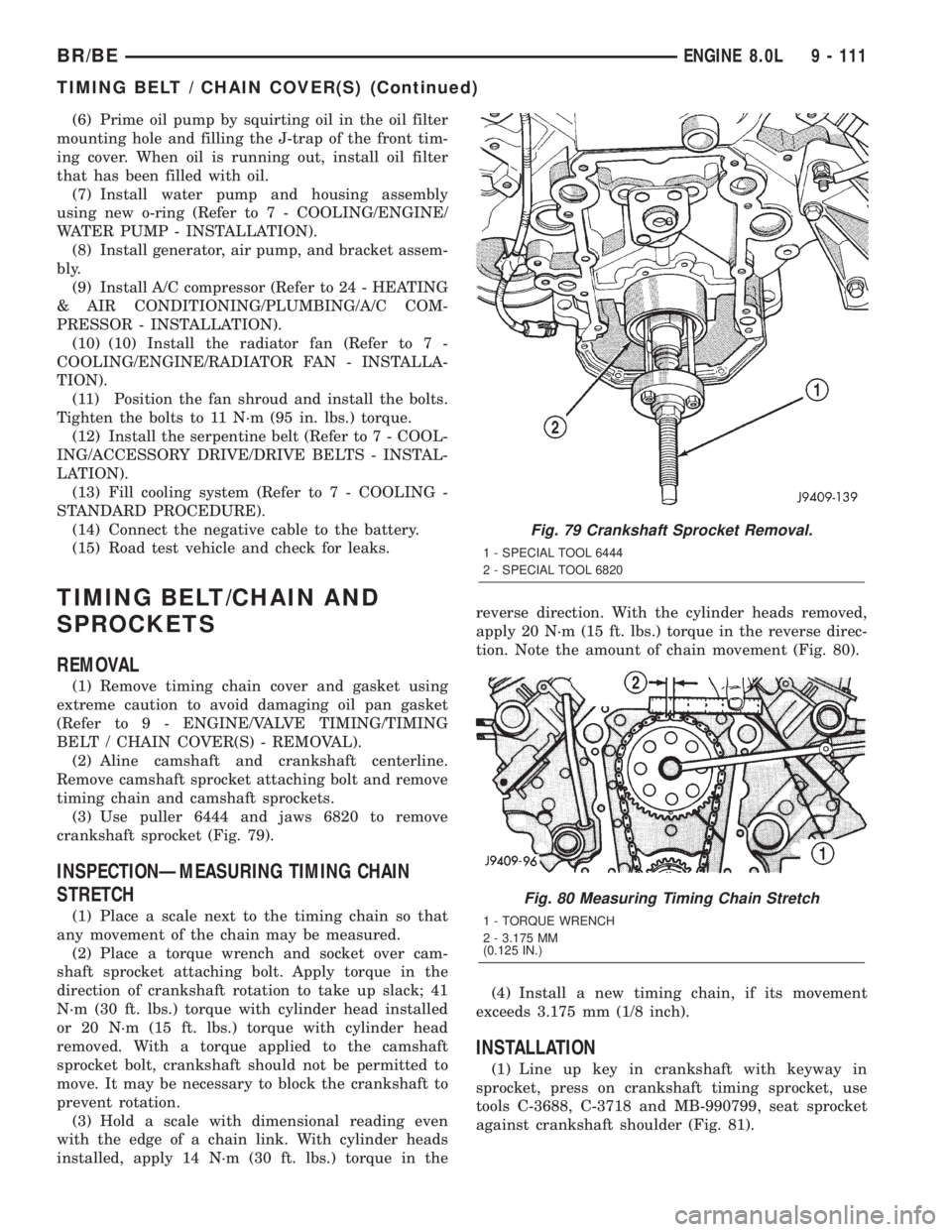
crankshaft sprocket (Fig. 79).
INSPECTIONÐMEASURING TIMING CHAIN
STRETCH
(1) Place a scale next to the timing chain so that
any movement of the chain may be measured.
(2) Place a torque wrench and socket over cam-
shaft sprocket attaching bolt. Apply torque in the
direction of crankshaft rotation to take up slack; 41
N´m (30 ft. lbs.) torque with cylinder head installed
or 20 N´m (15 ft. lbs.) torque with cylinder head
removed. With a torque applied to the camshaft
sprocket bolt, crankshaft should not be permitted to
move. It may be necessary to block the crankshaft to
prevent rotation.
(3) Hold a scale with dimensional reading even
with the edge of a chain link. With cylinder heads
installed, apply 14 N´m (30 ft. lbs.) torque in thereverse direction. With the cylinder heads removed,
apply 20 N´m (15 ft. lbs.) torque in the reverse direc-
tion. Note the amount of chain movement (Fig. 80).
(4) Install a new timing chain, if its movement
exceeds 3.175 mm (1/8 inch).
INSTALLATION
(1) Line up key in crankshaft with keyway in
sprocket, press on crankshaft timing sprocket, use
tools C-3688, C-3718 and MB-990799, seat sprocket
against crankshaft shoulder (Fig. 81).
Fig. 79 Crankshaft Sprocket Removal.
1 - SPECIAL TOOL 6444
2 - SPECIAL TOOL 6820
Fig. 80 Measuring Timing Chain Stretch
1 - TORQUE WRENCH
2 - 3.175 MM
(0.125 IN.)
BR/BEENGINE 8.0L 9 - 111
TIMING BELT / CHAIN COVER(S) (Continued)
Page 1188 of 2255
ENGINE 5.9L DIESEL
TABLE OF CONTENTS
page page
ENGINE 5.9L DIESEL
DESCRIPTION........................115
DIAGNOSIS AND TESTING
DIAGNOSIS AND TESTINGÐENGINE
DIAGNOSIS - MECHANICAL............116
DIAGNOSIS AND TESTINGÐSMOKE
DIAGNOSIS CHARTS..................118
STANDARD PROCEDURE
STANDARD PROCEDURE - FORM-IN-
PLACE GASKETS AND SEALERS........122
STANDARD PROCEDURE - REPAIR
DAMAGED OR WORN THREADS........122
STANDARD PROCEDUREÐHYDROSTATIC
LOCK..............................122
REMOVAL
REMOVALÐENGINE..................123
REMOVALÐCRANKCASE BREATHER
VAPOR CANISTER...................125
INSTALLATION
INSTALLATIONÐENGINE..............125
INSTALLATIONÐCRANKCASE BREATHER
VAPOR CANISTER...................126
SPECIFICATIONS
5.9L DIESEL........................127
TORQUE...........................127
SPECIAL TOOLS
5.9L DIESEL ENGINE.................128
ENGINE DATA PLATE
DESCRIPTION........................129
AIR CLEANER ELEMENT
REMOVAL............................129
INSTALLATION........................130
CYLINDER HEAD
DESCRIPTION........................130
REMOVAL............................130
CLEANING
CLEANINGÐCYLINDER HEAD..........134
CLEANINGÐCROSSHEADS............134
CLEANINGÐPUSHRODS..............134
INSPECTION
INSPECTIONÐCYLINDER HEAD.........134
INSPECTIONÐCROSSHEADS..........135
INSPECTIONÐPUSHRODS.............135
INSTALLATION........................136
CYLINDER HEAD COVER(S)
REMOVAL............................137
CLEANING...........................137
INSPECTION.........................138
INSTALLATION........................138INTAKE/EXHAUST VALVES & SEATS
DESCRIPTION........................138
STANDARD PROCEDURE
STANDARD PROCEDURE -
VALVES,GUIDES AND SPRINGS.........138
STANDARD PROCEDUREÐVALVE LASH
ADJUSTMENT AND VERIFICATION.......141
REMOVAL............................143
INSTALLATION........................143
ROCKER ARM / ADJUSTER ASSY
DESCRIPTION........................145
REMOVAL............................145
CLEANING...........................146
INSPECTION.........................146
INSTALLATION........................148
ENGINE BLOCK
STANDARD PROCEDURE
STANDARD PROCEDURE - CYLINDER
BLOCK REFACING...................148
STANDARD PROCEDURE - CYLINDER
BORE - DE-GLAZE...................148
STANDARD PROCEDUREÐCYLINDER
BORE REPAIR.......................149
STANDARD PROCEDUREÐCAM BORE
REPAIR ............................151
INSPECTION.........................151
CAMSHAFT & BEARINGS (IN BLOCK)
REMOVAL
REMOVALÐCAMSHAFT BEARINGS......152
REMOVALÐCAMSHAFT...............152
INSPECTION.........................155
INSTALLATION
INSTALLATIONÐCAMSHAFT BEARINGS . . 157
INSTALLATIONÐCAMSHAFT............157
CONNECTING ROD BEARINGS
STANDARD PROCEDUREÐCONNECTING
ROD BEARING AND CRANKSHAFT
JOURNAL CLEARANCE................158
CRANKSHAFT
DESCRIPTION........................159
CRANKSHAFT MAIN BEARINGS
STANDARD PROCEDUREÐMAIN BEARING
CLEARANCE........................159
CRANKSHAFT OIL SEAL - FRONT
REMOVAL............................160
INSTALLATION........................160
CRANKSHAFT OIL SEAL - REAR
REMOVAL............................161
INSTALLATION........................162
BR/BEENGINE 5.9L DIESEL 9 - 113
Page 1189 of 2255
CRANKSHAFT REAR OIL SEAL RETAINER
REMOVAL............................162
INSTALLATION........................163
SOLID LIFTERS/TAPPETS
REMOVAL............................164
CLEANING...........................164
INSPECTION.........................165
INSTALLATION........................165
PISTON & CONNECTING ROD
DESCRIPTION........................165
STANDARD PROCEDUREÐPISTON
GRADING..........................166
REMOVAL............................168
CLEANING...........................169
INSPECTION
INSPECTION........................169
Connecting Rods.....................169
INSTALLATION........................170
PISTON RINGS
STANDARD PROCEDURE - PISTON RING
FITTING............................171
VIBRATION DAMPER
REMOVAL............................172
INSPECTION.........................172
INSTALLATION........................173
FRONT MOUNT
REMOVAL............................173
INSTALLATION........................174
REAR MOUNT
REMOVAL............................174
INSTALLATION........................174
LUBRICATION
DESCRIPTION........................174
OPERATION..........................174
DIAGNOSIS AND TESTINGÐENGINE OIL
PRESSURE.........................178
OIL
STANDARD PROCEDURE
STANDARD PROCEDURE - ENGINE OIL
LEVEL.............................178
STANDARD PROCEDURE - ENGINE OIL
SERVICE...........................178OIL COOLER & LINES
CLEANING AND INSPECTION............179
OIL FILTER
REMOVAL............................179
INSTALLATION........................179
OIL PAN
REMOVAL............................179
CLEANING...........................179
INSPECTION.........................179
INSTALLATION........................180
OIL PRESSURE RELIEF VALVE
REMOVAL............................180
CLEANING...........................180
INSPECTION.........................180
INSTALLATION........................180
OIL PRESSURE SENSOR/SWITCH
REMOVAL............................181
INSTALLATION........................181
OIL PUMP
REMOVAL............................181
CLEANING...........................181
INSPECTION.........................181
INSTALLATION........................182
INTAKE MANIFOLD
REMOVAL............................184
CLEANING...........................184
INSPECTION.........................184
INSTALLATION........................184
EXHAUST MANIFOLD
REMOVAL............................185
CLEANING...........................185
INSPECTION.........................186
INSTALLATION........................186
VALVE TIMING
STANDARD PROCEDURE - TIMING
VERIFICATION.......................187
GEAR HOUSING
REMOVAL............................187
INSTALLATION........................188
GEAR HOUSING COVER
REMOVAL............................189
INSTALLATION........................190
9 - 114 ENGINE 5.9L DIESELBR/BE
Page 1190 of 2255
ENGINE 5.9L DIESEL
DESCRIPTION
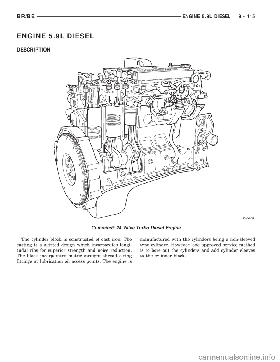
The cylinder block is constructed of cast iron. The
casting is a skirted design which incorporates longi-
tudal ribs for superior strength and noise reduction.
The block incorporates metric straight thread o-ring
fittings at lubrication oil access points. The engine ismanufactured with the cylinders being a non-sleeved
type cylinder. However, one approved service method
is to bore out the cylinders and add cylinder sleeves
to the cylinder block.
CumminsT24 Valve Turbo Diesel Engine
BR/BEENGINE 5.9L DIESEL 9 - 115
Page 1191 of 2255
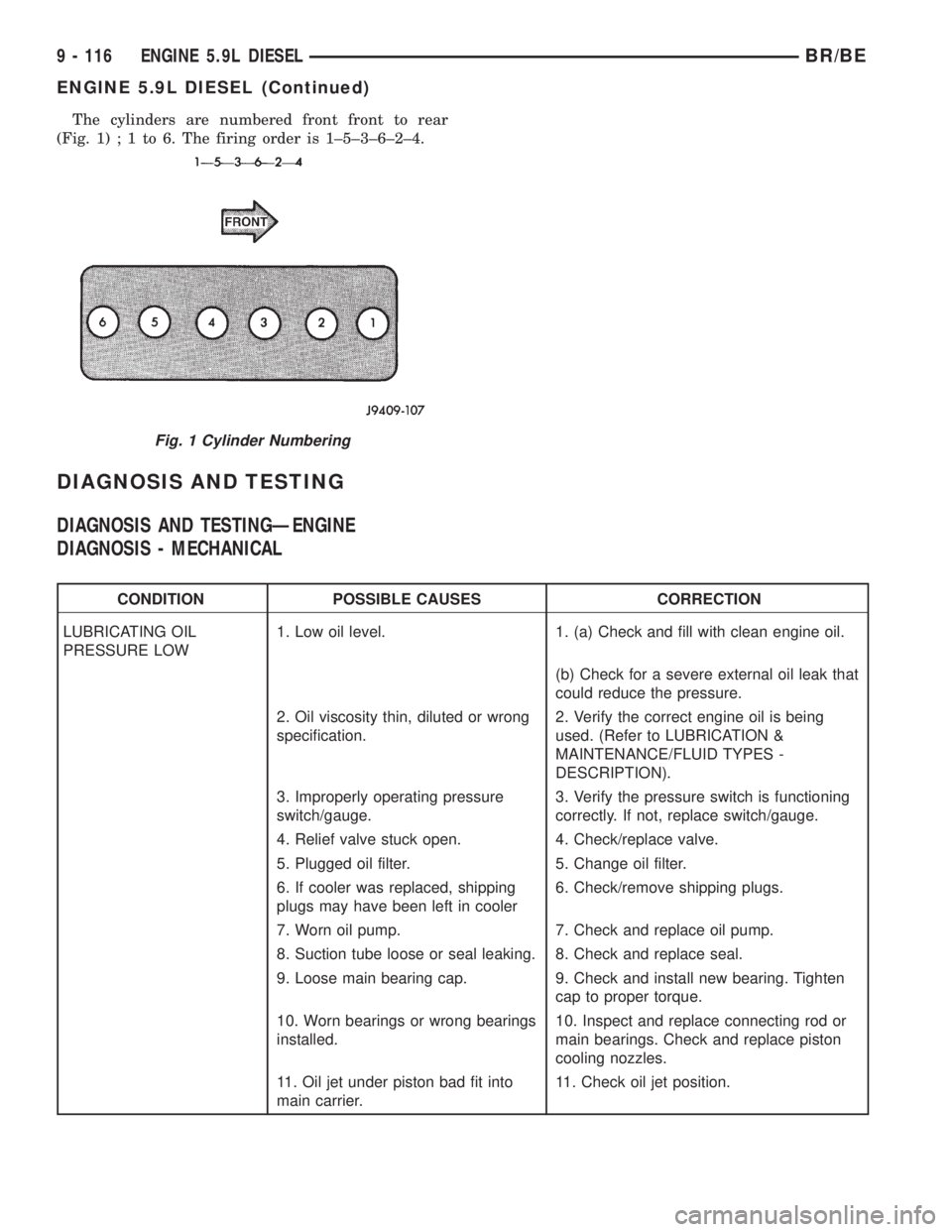
The cylinders are numbered front front to rear
(Fig. 1);1to6.Thefiring order is 1±5±3±6±2±4.
DIAGNOSIS AND TESTING
DIAGNOSIS AND TESTINGÐENGINE
DIAGNOSIS - MECHANICAL
CONDITION POSSIBLE CAUSES CORRECTION
LUBRICATING OIL
PRESSURE LOW1. Low oil level. 1. (a) Check and fill with clean engine oil.
(b) Check for a severe external oil leak that
could reduce the pressure.
2. Oil viscosity thin, diluted or wrong
specification.2. Verify the correct engine oil is being
used. (Refer to LUBRICATION &
MAINTENANCE/FLUID TYPES -
DESCRIPTION).
3. Improperly operating pressure
switch/gauge.3. Verify the pressure switch is functioning
correctly. If not, replace switch/gauge.
4. Relief valve stuck open. 4. Check/replace valve.
5. Plugged oil filter. 5. Change oil filter.
6. If cooler was replaced, shipping
plugs may have been left in cooler6. Check/remove shipping plugs.
7. Worn oil pump. 7. Check and replace oil pump.
8. Suction tube loose or seal leaking. 8. Check and replace seal.
9. Loose main bearing cap. 9. Check and install new bearing. Tighten
cap to proper torque.
10. Worn bearings or wrong bearings
installed.10. Inspect and replace connecting rod or
main bearings. Check and replace piston
cooling nozzles.
11. Oil jet under piston bad fit into
main carrier.11. Check oil jet position.
Fig. 1 Cylinder Numbering
9 - 116 ENGINE 5.9L DIESELBR/BE
ENGINE 5.9L DIESEL (Continued)
Page 1192 of 2255
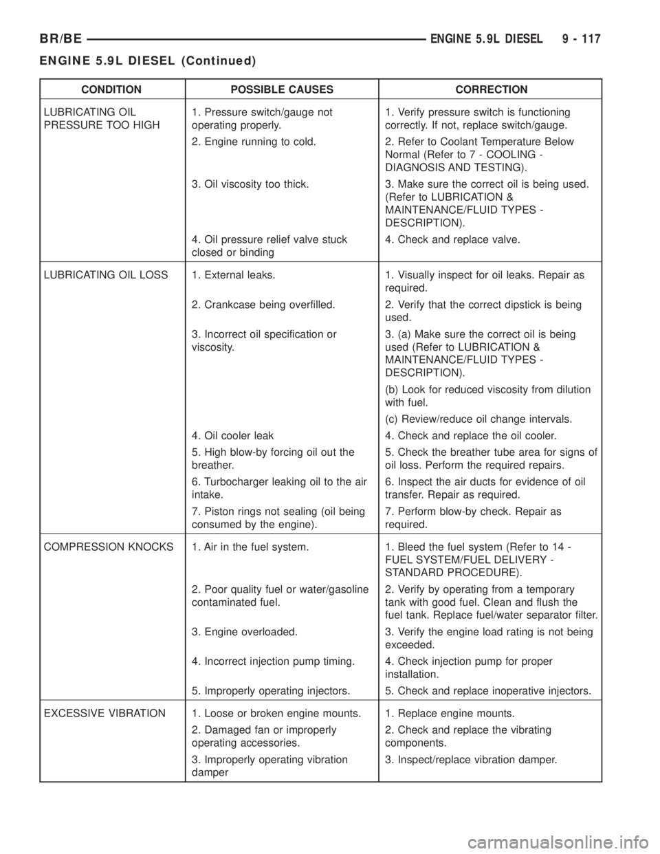
CONDITION POSSIBLE CAUSES CORRECTION
LUBRICATING OIL
PRESSURE TOO HIGH1. Pressure switch/gauge not
operating properly.1. Verify pressure switch is functioning
correctly. If not, replace switch/gauge.
2. Engine running to cold. 2. Refer to Coolant Temperature Below
Normal (Refer to 7 - COOLING -
DIAGNOSIS AND TESTING).
3. Oil viscosity too thick. 3. Make sure the correct oil is being used.
(Refer to LUBRICATION &
MAINTENANCE/FLUID TYPES -
DESCRIPTION).
4. Oil pressure relief valve stuck
closed or binding4. Check and replace valve.
LUBRICATING OIL LOSS 1. External leaks. 1. Visually inspect for oil leaks. Repair as
required.
2. Crankcase being overfilled. 2. Verify that the correct dipstick is being
used.
3. Incorrect oil specification or
viscosity.3. (a) Make sure the correct oil is being
used (Refer to LUBRICATION &
MAINTENANCE/FLUID TYPES -
DESCRIPTION).
(b) Look for reduced viscosity from dilution
with fuel.
(c) Review/reduce oil change intervals.
4. Oil cooler leak 4. Check and replace the oil cooler.
5. High blow-by forcing oil out the
breather.5. Check the breather tube area for signs of
oil loss. Perform the required repairs.
6. Turbocharger leaking oil to the air
intake.6. Inspect the air ducts for evidence of oil
transfer. Repair as required.
7. Piston rings not sealing (oil being
consumed by the engine).7. Perform blow-by check. Repair as
required.
COMPRESSION KNOCKS 1. Air in the fuel system. 1. Bleed the fuel system (Refer to 14 -
FUEL SYSTEM/FUEL DELIVERY -
STANDARD PROCEDURE).
2. Poor quality fuel or water/gasoline
contaminated fuel.2. Verify by operating from a temporary
tank with good fuel. Clean and flush the
fuel tank. Replace fuel/water separator filter.
3. Engine overloaded. 3. Verify the engine load rating is not being
exceeded.
4. Incorrect injection pump timing. 4. Check injection pump for proper
installation.
5. Improperly operating injectors. 5. Check and replace inoperative injectors.
EXCESSIVE VIBRATION 1. Loose or broken engine mounts. 1. Replace engine mounts.
2. Damaged fan or improperly
operating accessories.2. Check and replace the vibrating
components.
3. Improperly operating vibration
damper3. Inspect/replace vibration damper.
BR/BEENGINE 5.9L DIESEL 9 - 117
ENGINE 5.9L DIESEL (Continued)
Page 1195 of 2255
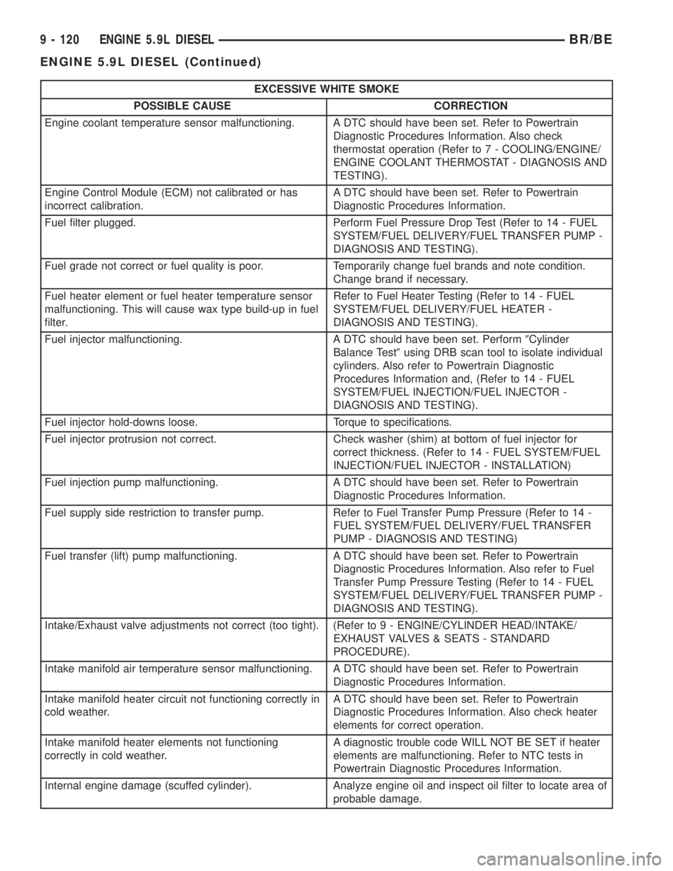
EXCESSIVE WHITE SMOKE
POSSIBLE CAUSE CORRECTION
Engine coolant temperature sensor malfunctioning. A DTC should have been set. Refer to Powertrain
Diagnostic Procedures Information. Also check
thermostat operation (Refer to 7 - COOLING/ENGINE/
ENGINE COOLANT THERMOSTAT - DIAGNOSIS AND
TESTING).
Engine Control Module (ECM) not calibrated or has
incorrect calibration.A DTC should have been set. Refer to Powertrain
Diagnostic Procedures Information.
Fuel filter plugged. Perform Fuel Pressure Drop Test (Refer to 14 - FUEL
SYSTEM/FUEL DELIVERY/FUEL TRANSFER PUMP -
DIAGNOSIS AND TESTING).
Fuel grade not correct or fuel quality is poor. Temporarily change fuel brands and note condition.
Change brand if necessary.
Fuel heater element or fuel heater temperature sensor
malfunctioning. This will cause wax type build-up in fuel
filter.Refer to Fuel Heater Testing (Refer to 14 - FUEL
SYSTEM/FUEL DELIVERY/FUEL HEATER -
DIAGNOSIS AND TESTING).
Fuel injector malfunctioning. A DTC should have been set. Perform9Cylinder
Balance Test9using DRB scan tool to isolate individual
cylinders. Also refer to Powertrain Diagnostic
Procedures Information and, (Refer to 14 - FUEL
SYSTEM/FUEL INJECTION/FUEL INJECTOR -
DIAGNOSIS AND TESTING).
Fuel injector hold-downs loose. Torque to specifications.
Fuel injector protrusion not correct. Check washer (shim) at bottom of fuel injector for
correct thickness. (Refer to 14 - FUEL SYSTEM/FUEL
INJECTION/FUEL INJECTOR - INSTALLATION)
Fuel injection pump malfunctioning. A DTC should have been set. Refer to Powertrain
Diagnostic Procedures Information.
Fuel supply side restriction to transfer pump. Refer to Fuel Transfer Pump Pressure (Refer to 14 -
FUEL SYSTEM/FUEL DELIVERY/FUEL TRANSFER
PUMP - DIAGNOSIS AND TESTING)
Fuel transfer (lift) pump malfunctioning. A DTC should have been set. Refer to Powertrain
Diagnostic Procedures Information. Also refer to Fuel
Transfer Pump Pressure Testing (Refer to 14 - FUEL
SYSTEM/FUEL DELIVERY/FUEL TRANSFER PUMP -
DIAGNOSIS AND TESTING).
Intake/Exhaust valve adjustments not correct (too tight). (Refer to 9 - ENGINE/CYLINDER HEAD/INTAKE/
EXHAUST VALVES & SEATS - STANDARD
PROCEDURE).
Intake manifold air temperature sensor malfunctioning. A DTC should have been set. Refer to Powertrain
Diagnostic Procedures Information.
Intake manifold heater circuit not functioning correctly in
cold weather.A DTC should have been set. Refer to Powertrain
Diagnostic Procedures Information. Also check heater
elements for correct operation.
Intake manifold heater elements not functioning
correctly in cold weather.A diagnostic trouble code WILL NOT BE SET if heater
elements are malfunctioning. Refer to NTC tests in
Powertrain Diagnostic Procedures Information.
Internal engine damage (scuffed cylinder). Analyze engine oil and inspect oil filter to locate area of
probable damage.
9 - 120 ENGINE 5.9L DIESELBR/BE
ENGINE 5.9L DIESEL (Continued)
Page 1196 of 2255
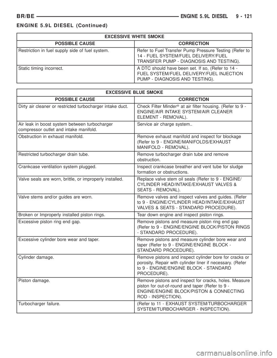
EXCESSIVE WHITE SMOKE
POSSIBLE CAUSE CORRECTION
Restriction in fuel supply side of fuel system. Refer to Fuel Transfer Pump Pressure Testing (Refer to
14 - FUEL SYSTEM/FUEL DELIVERY/FUEL
TRANSFER PUMP - DIAGNOSIS AND TESTING).
Static timing incorrect. A DTC should have been set. If so, (Refer to 14 -
FUEL SYSTEM/FUEL DELIVERY/FUEL INJECTION
PUMP - DIAGNOSIS AND TESTING).
EXCESSIVE BLUE SMOKE
POSSIBLE CAUSE CORRECTION
Dirty air cleaner or restricted turbocharger intake duct. Check Filter MinderTat air filter housing. (Refer to 9 -
ENGINE/AIR INTAKE SYSTEM/AIR CLEANER
ELEMENT - REMOVAL).
Air leak in boost system between turbocharger
compressor outlet and intake manifold.Service air charge system..
Obstruction in exhaust manifold. Remove exhaust manifold and inspect for blockage
(Refer to 9 - ENGINE/MANIFOLDS/EXHAUST
MANIFOLD - REMOVAL).
Restricted turbocharger drain tube. Remove turbocharger drain tube and remove
obstruction.
Crankcase ventilation system plugged. Inspect crankcase breather and vent tube for sludge
formation or obstructions.
Valve seals are worn, brittle, or improperly installed. Replace valve stem oil seals (Refer to 9 - ENGINE/
CYLINDER HEAD/INTAKE/EXHAUST VALVES &
SEATS - REMOVAL).
Valve stems and/or guides are worn. Remove valves and inspect valves and guides. (Refer
to 9 - ENGINE/CYLINDER HEAD/INTAKE/EXHAUST
VALVES & SEATS - STANDARD PROCEDURE).
Broken or Improperly installed piston rings. Tear down engine and inspect piston rings.
Excessive piston ring end gap. Remove pistons and measure piston ring end gap
(Refer to 9 - ENGINE/ENGINE BLOCK/PISTON RINGS
- STANDARD PROCEDURE).
Excessive cylinder bore wear and taper. Remove pistons and measure cylinder bore wear and
taper (Refer to 9 - ENGINE/ENGINE BLOCK -
STANDARD PROCEDURE).
Cylinder damage. Remove pistons and inspect cylinder bore for cracks or
porosity. Repair with cylinder liner if necessary. (Refer
to 9 - ENGINE/ENGINE BLOCK - STANDARD
PROCEDURE).
Piston damage. Remove pistons and inspect for cracks, holes. Measure
piston for out-of-round and taper (Refer to 9 -
ENGINE/ENGINE BLOCK/PISTON & CONNECTING
ROD - INSPECTION).
Turbocharger failure. (Refer to 11 - EXHAUST SYSTEM/TURBOCHARGER
SYSTEM/TURBOCHARGER - INSPECTION).
BR/BEENGINE 5.9L DIESEL 9 - 121
ENGINE 5.9L DIESEL (Continued)