2002 DODGE RAM clutch
[x] Cancel search: clutchPage 1564 of 2255
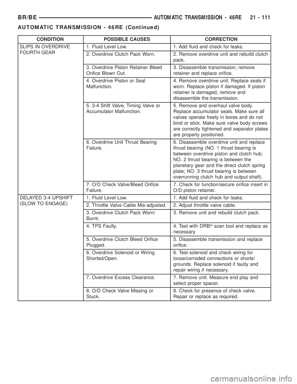
CONDITION POSSIBLE CAUSES CORRECTION
SLIPS IN OVERDRIVE
FOURTH GEAR1. Fluid Level Low. 1. Add fluid and check for leaks.
2. Overdrive Clutch Pack Worn. 2. Remove overdrive unit and rebuild clutch
pack.
3. Overdrive Piston Retainer Bleed
Orifice Blown Out.3. Disassemble transmission, remove
retainer and replace orifice.
4. Overdrive Piston or Seal
Malfunction.4. Remove overdrive unit. Replace seals if
worn. Replace piston if damaged. If piston
retainer is damaged, remove and
disassemble the transmission.
5. 3-4 Shift Valve, Timing Valve or
Accumulator Malfunction.5. Remove and overhaul valve body.
Replace accumulator seals. Make sure all
valves operate freely in bores and do not
bind or stick. Make sure valve body screws
are correctly tightened and separator plates
are properly positioned.
6. Overdrive Unit Thrust Bearing
Failure.6. Disassemble overdrive unit and replace
thrust bearing (NO. 1 thrust bearing is
between overdrive piston and clutch hub;
NO. 2 thrust bearing is between the
planetary gear and the direct clutch spring
plate; NO. 3 thrust bearing is between
overrunning clutch hub and output shaft).
7. O/D Check Valve/Bleed Orifice
Failure.7. Check for function/secure orifice insert in
O/D piston retainer.
DELAYED 3-4 UPSHIFT
(SLOW TO ENGAGE)1. Fluid Level Low. 1. Add fluid and check for leaks.
2. Throttle Valve Cable Mis-adjusted. 2. Adjust throttle valve cable.
3. Overdrive Clutch Pack Worn/
Burnt.3. Remove unit and rebuild clutch pack.
4. TPS Faulty. 4. Test with DRBTscan tool and replace as
necessary
5. Overdrive Clutch Bleed Orifice
Plugged.5. Disassemble transmission and replace
orifice.
6. Overdrive Solenoid or Wiring
Shorted/Open.6. Test solenoid and check wiring for
loose/corroded connections or shorts/
grounds. Replace solenoid if faulty and
repair wiring if necessary.
7. Overdrive Excess Clearance. 7. Remove unit. Measure end play and
select proper spacer.
8. O/D Check Valve Missing or
Stuck.8. Check for presence of check valve.
Repair or replace as required.
BR/BEAUTOMATIC TRANSMISSION - 46RE 21 - 111
AUTOMATIC TRANSMISSION - 46RE (Continued)
Page 1565 of 2255
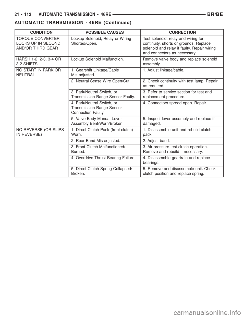
CONDITION POSSIBLE CAUSES CORRECTION
TORQUE CONVERTER
LOCKS UP IN SECOND
AND/OR THIRD GEARLockup Solenoid, Relay or Wiring
Shorted/Open.Test solenoid, relay and wiring for
continuity, shorts or grounds. Replace
solenoid and relay if faulty. Repair wiring
and connectors as necessary.
HARSH 1-2, 2-3, 3-4 OR
3-2 SHIFTSLockup Solenoid Malfunction. Remove valve body and replace solenoid
assembly.
NO START IN PARK OR
NEUTRAL1. Gearshift Linkage/Cable
Mis-adjusted.1. Adjust linkage/cable.
2. Neutral Sense Wire Open/Cut. 2. Check continuity with test lamp. Repair
as required.
3. Park/Neutral Switch, or
Transmission Range Sensor Faulty.3. Refer to service section for test and
replacement procedure.
4. Park/Neutral Switch, or
Transmission Range Sensor
Connection Faulty.4. Connectors spread open. Repair.
5. Valve Body Manual Lever
Assembly Bent/Worn/Broken.5. Inspect lever assembly and replace if
damaged.
NO REVERSE (OR SLIPS
IN REVERSE)1. Direct Clutch Pack (front clutch)
Worn.1. Disassemble unit and rebuild clutch
pack.
2. Rear Band Mis-adjusted. 2. Adjust band.
3. Front Clutch Malfunctioned/
Burned.3. Air-pressure test clutch operation.
Remove and rebuild if necessary.
4. Overdrive Thrust Bearing Failure. 4. Disassemble geartrain and replace
bearings.
5. Direct Clutch Spring Collapsed/
Broken.5. Remove and disassemble unit. Check
clutch position and replace spring.
21 - 112 AUTOMATIC TRANSMISSION - 46REBR/BE
AUTOMATIC TRANSMISSION - 46RE (Continued)
Page 1566 of 2255
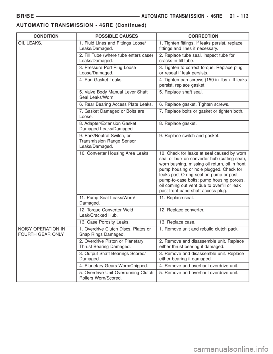
CONDITION POSSIBLE CAUSES CORRECTION
OIL LEAKS. 1. Fluid Lines and Fittings Loose/
Leaks/Damaged.1. Tighten fittings. If leaks persist, replace
fittings and lines if necessary.
2. Fill Tube (where tube enters case)
Leaks/Damaged.2. Replace tube seal. Inspect tube for
cracks in fill tube.
3. Pressure Port Plug Loose
Loose/Damaged.3. Tighten to correct torque. Replace plug
or reseal if leak persists.
4. Pan Gasket Leaks. 4. Tighten pan screws (150 in. lbs.). If leaks
persist, replace gasket.
5. Valve Body Manual Lever Shaft
Seal Leaks/Worn.5. Replace shaft seal.
6. Rear Bearing Access Plate Leaks. 6. Replace gasket. Tighten screws.
7. Gasket Damaged or Bolts are
Loose.7. Replace bolts or gasket or tighten both.
8. Adapter/Extension Gasket
Damaged Leaks/Damaged.8. Replace gasket.
9. Park/Neutral Switch, or
Transmission Range Sensor
Leaks/Damaged.9. Replace switch and gasket.
10. Converter Housing Area Leaks. 10. Check for leaks at seal caused by worn
seal or burr on converter hub (cutting seal),
worn bushing, missing oil return, oil in front
pump housing or hole plugged. Check for
leaks past O-ring seal on pump or past
pump-to-case bolts; pump housing porous,
oil coming out vent due to overfill or leak
past front band shaft access plug.
11. Pump Seal Leaks/Worn/
Damaged.11. Replace seal.
12. Torque Converter Weld
Leak/Cracked Hub.12. Replace converter.
13. Case Porosity Leaks. 13. Replace case.
NOISY OPERATION IN
FOURTH GEAR ONLY1. Overdrive Clutch Discs, Plates or
Snap Rings Damaged.1. Remove unit and rebuild clutch pack.
2. Overdrive Piston or Planetary
Thrust Bearing Damaged.2. Remove and disassemble unit. Replace
either thrust bearing if damaged.
3. Output Shaft Bearings Scored/
Damaged.3. Remove and disassemble unit. Replace
either bearing if damaged.
4. Planetary Gears Worn/Chipped. 4. Remove and overhaul overdrive unit.
5. Overdrive Unit Overrunning Clutch
Rollers Worn/Scored.5. Remove and overhaul overdrive unit.
BR/BEAUTOMATIC TRANSMISSION - 46RE 21 - 113
AUTOMATIC TRANSMISSION - 46RE (Continued)
Page 1570 of 2255
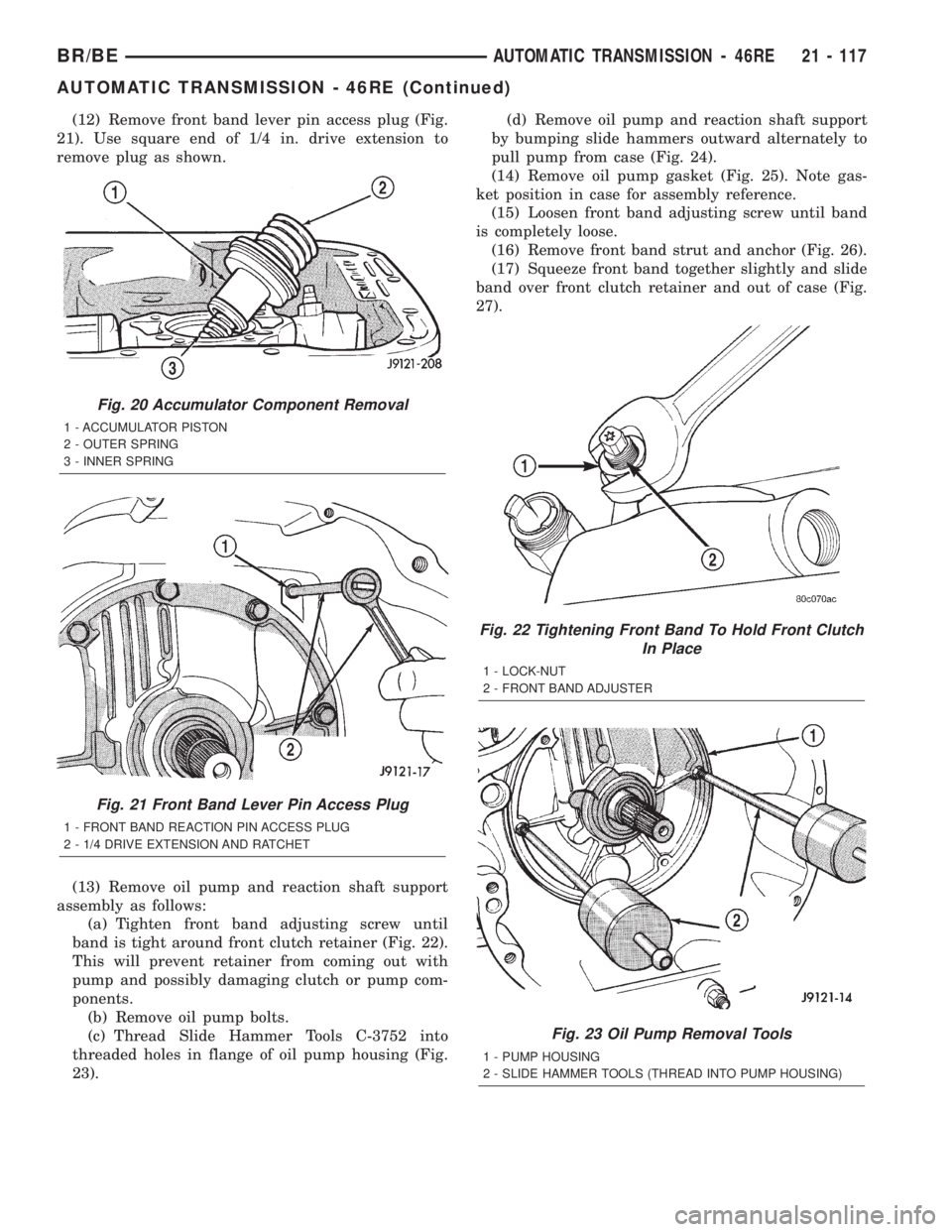
(12) Remove front band lever pin access plug (Fig.
21). Use square end of 1/4 in. drive extension to
remove plug as shown.
(13) Remove oil pump and reaction shaft support
assembly as follows:
(a) Tighten front band adjusting screw until
band is tight around front clutch retainer (Fig. 22).
This will prevent retainer from coming out with
pump and possibly damaging clutch or pump com-
ponents.
(b) Remove oil pump bolts.
(c) Thread Slide Hammer Tools C-3752 into
threaded holes in flange of oil pump housing (Fig.
23).(d) Remove oil pump and reaction shaft support
by bumping slide hammers outward alternately to
pull pump from case (Fig. 24).
(14) Remove oil pump gasket (Fig. 25). Note gas-
ket position in case for assembly reference.
(15) Loosen front band adjusting screw until band
is completely loose.
(16) Remove front band strut and anchor (Fig. 26).
(17) Squeeze front band together slightly and slide
band over front clutch retainer and out of case (Fig.
27).
Fig. 20 Accumulator Component Removal
1 - ACCUMULATOR PISTON
2 - OUTER SPRING
3 - INNER SPRING
Fig. 21 Front Band Lever Pin Access Plug
1 - FRONT BAND REACTION PIN ACCESS PLUG
2 - 1/4 DRIVE EXTENSION AND RATCHET
Fig. 22 Tightening Front Band To Hold Front Clutch
In Place
1 - LOCK-NUT
2 - FRONT BAND ADJUSTER
Fig. 23 Oil Pump Removal Tools
1 - PUMP HOUSING
2 - SLIDE HAMMER TOOLS (THREAD INTO PUMP HOUSING)
BR/BEAUTOMATIC TRANSMISSION - 46RE 21 - 117
AUTOMATIC TRANSMISSION - 46RE (Continued)
Page 1571 of 2255
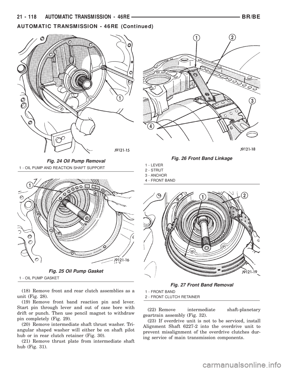
(18) Remove front and rear clutch assemblies as a
unit (Fig. 28).
(19) Remove front band reaction pin and lever.
Start pin through lever and out of case bore with
drift or punch. Then use pencil magnet to withdraw
pin completely (Fig. 29).
(20) Remove intermediate shaft thrust washer. Tri-
angular shaped washer will either be on shaft pilot
hub or in rear clutch retainer (Fig. 30).
(21) Remove thrust plate from intermediate shaft
hub (Fig. 31).(22) Remove intermediate shaft-planetary
geartrain assembly (Fig. 32).
(23) If overdrive unit is not to be serviced, install
Alignment Shaft 6227-2 into the overdrive unit to
prevent misalignment of the overdrive clutches dur-
ing service of main transmission components.
Fig. 24 Oil Pump Removal
1 - OIL PUMP AND REACTION SHAFT SUPPORT
Fig. 25 Oil Pump Gasket
1 - OIL PUMP GASKET
Fig. 26 Front Band Linkage
1 - LEVER
2 - STRUT
3 - ANCHOR
4 - FRONT BAND
Fig. 27 Front Band Removal
1 - FRONT BAND
2 - FRONT CLUTCH RETAINER
21 - 118 AUTOMATIC TRANSMISSION - 46REBR/BE
AUTOMATIC TRANSMISSION - 46RE (Continued)
Page 1572 of 2255
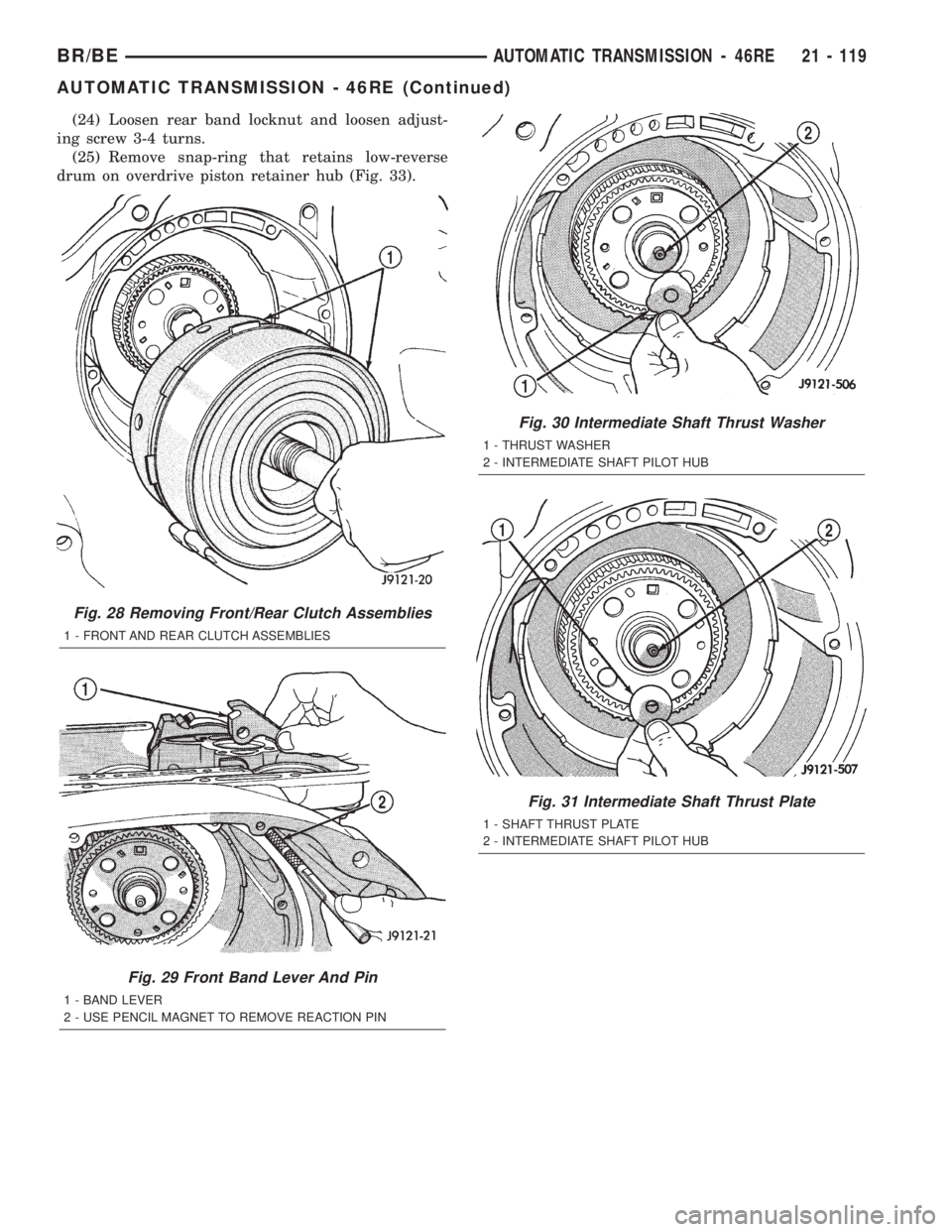
(24) Loosen rear band locknut and loosen adjust-
ing screw 3-4 turns.
(25) Remove snap-ring that retains low-reverse
drum on overdrive piston retainer hub (Fig. 33).
Fig. 28 Removing Front/Rear Clutch Assemblies
1 - FRONT AND REAR CLUTCH ASSEMBLIES
Fig. 29 Front Band Lever And Pin
1 - BAND LEVER
2 - USE PENCIL MAGNET TO REMOVE REACTION PIN
Fig. 30 Intermediate Shaft Thrust Washer
1 - THRUST WASHER
2 - INTERMEDIATE SHAFT PILOT HUB
Fig. 31 Intermediate Shaft Thrust Plate
1 - SHAFT THRUST PLATE
2 - INTERMEDIATE SHAFT PILOT HUB
BR/BEAUTOMATIC TRANSMISSION - 46RE 21 - 119
AUTOMATIC TRANSMISSION - 46RE (Continued)
Page 1573 of 2255
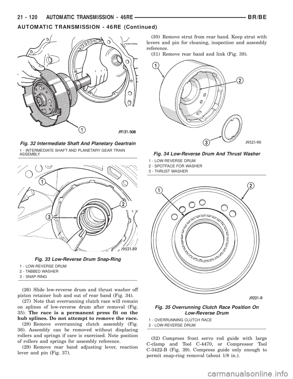
(26) Slide low-reverse drum and thrust washer off
piston retainer hub and out of rear band (Fig. 34).
(27) Note that overrunning clutch race will remain
on splines of low-reverse drum after removal (Fig.
35).The race is a permanent press fit on the
hub splines. Do not attempt to remove the race.
(28) Remove overrunning clutch assembly (Fig.
36). Assembly can be removed without displacing
rollers and springs if care is exercised. Note position
of rollers and springs for assembly reference.
(29) Remove rear band adjusting lever, reaction
lever and pin (Fig. 37).(30) Remove strut from rear band. Keep strut with
levers and pin for cleaning, inspection and assembly
reference.
(31) Remove rear band and link (Fig. 38).
(32) Compress front servo rod guide with large
C-clamp and Tool C-4470, or Compressor Tool
C-3422-B (Fig. 39). Compress guide only enough to
permit snap-ring removal (about 1/8 in.).
Fig. 32 Intermediate Shaft And Planetary Geartrain
1 - INTERMEDIATE SHAFT AND PLANETARY GEAR TRAIN
ASSEMBLY
Fig. 33 Low-Reverse Drum Snap-Ring
1 - LOW-REVERSE DRUM
2 - TABBED WASHER
3 - SNAP-RING
Fig. 34 Low-Reverse Drum And Thrust Washer
1 - LOW-REVERSE DRUM
2 - SPOTFACE FOR WASHER
3 - THRUST WASHER
Fig. 35 Overrunning Clutch Race Position On
Low-Reverse Drum
1 - OVERRUNNING CLUTCH RACE
2 - LOW-REVERSE DRUM
21 - 120 AUTOMATIC TRANSMISSION - 46REBR/BE
AUTOMATIC TRANSMISSION - 46RE (Continued)
Page 1574 of 2255
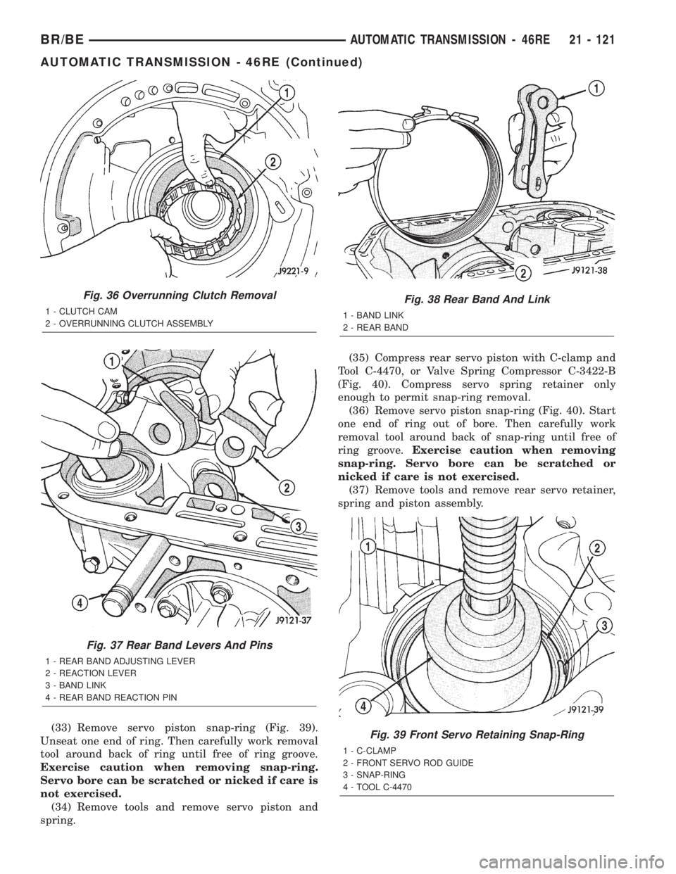
(33) Remove servo piston snap-ring (Fig. 39).
Unseat one end of ring. Then carefully work removal
tool around back of ring until free of ring groove.
Exercise caution when removing snap-ring.
Servo bore can be scratched or nicked if care is
not exercised.
(34) Remove tools and remove servo piston and
spring.(35) Compress rear servo piston with C-clamp and
Tool C-4470, or Valve Spring Compressor C-3422-B
(Fig. 40). Compress servo spring retainer only
enough to permit snap-ring removal.
(36) Remove servo piston snap-ring (Fig. 40). Start
one end of ring out of bore. Then carefully work
removal tool around back of snap-ring until free of
ring groove.Exercise caution when removing
snap-ring. Servo bore can be scratched or
nicked if care is not exercised.
(37) Remove tools and remove rear servo retainer,
spring and piston assembly.
Fig. 36 Overrunning Clutch Removal
1 - CLUTCH CAM
2 - OVERRUNNING CLUTCH ASSEMBLY
Fig. 37 Rear Band Levers And Pins
1 - REAR BAND ADJUSTING LEVER
2 - REACTION LEVER
3 - BAND LINK
4 - REAR BAND REACTION PIN
Fig. 38 Rear Band And Link
1 - BAND LINK
2 - REAR BAND
Fig. 39 Front Servo Retaining Snap-Ring
1 - C-CLAMP
2 - FRONT SERVO ROD GUIDE
3 - SNAP-RING
4 - TOOL C-4470
BR/BEAUTOMATIC TRANSMISSION - 46RE 21 - 121
AUTOMATIC TRANSMISSION - 46RE (Continued)