2002 DODGE RAM tire type
[x] Cancel search: tire typePage 104 of 2255

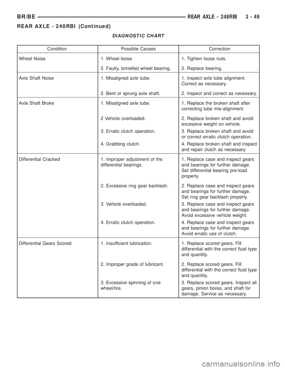
DIAGNOSTIC CHART
Condition Possible Causes Correction
Wheel Noise 1. Wheel loose. 1. Tighten loose nuts.
2. Faulty, brinelled wheel bearing. 2. Replace bearing.
Axle Shaft Noise 1. Misaligned axle tube. 1. Inspect axle tube alignment.
Correct as necessary.
2. Bent or sprung axle shaft. 2. Inspect and correct as necessary.
Axle Shaft Broke 1. Misaligned axle tube. 1. Replace the broken shaft after
correcting tube mis-alignment.
2 Vehicle overloaded. 2. Replace broken shaft and avoid
excessive weight on vehicle.
3. Erratic clutch operation. 3. Replace broken shaft and avoid
or correct erratic clutch operation.
4. Grabbing clutch. 4. Replace broken shaft and inspect
and repair clutch as necessary.
Differential Cracked 1. Improper adjustment of the
differential bearings.1. Replace case and inspect gears
and bearings for further damage.
Set differential bearing pre-load
properly.
2. Excessive ring gear backlash. 2. Replace case and inspect gears
and bearings for further damage.
Set ring gear backlash properly.
3. Vehicle overloaded. 3. Replace case and inspect gears
and bearings for further damage.
Avoid excessive vehicle weight.
4. Erratic clutch operation. 4. Replace case and inspect gears
and bearings for further damage.
Avoid erratic use of clutch.
Differential Gears Scored 1. Insufficient lubrication. 1. Replace scored gears. Fill
differential with the correct fluid type
and quantity.
2. Improper grade of lubricant. 2. Replace scored gears. Fill
differential with the correct fluid type
and quantity.
3. Excessive spinning of one
wheel/tire.3. Replace scored gears. Inspect all
gears, pinion bores, and shaft for
damage. Service as necessary.
BR/BEREAR AXLE - 248RBI 3 - 49
REAR AXLE - 248RBI (Continued)
Page 136 of 2255

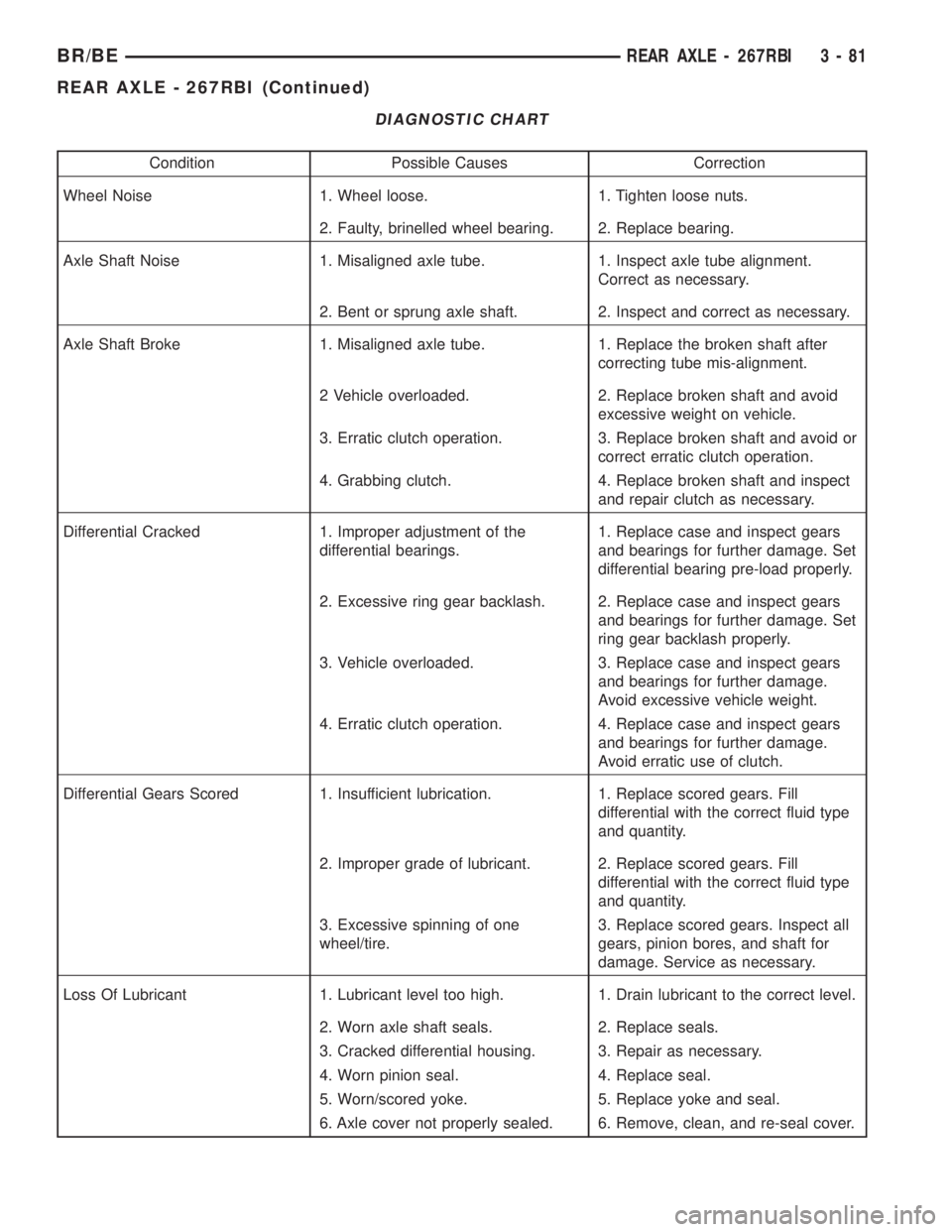
DIAGNOSTIC CHART
Condition Possible Causes Correction
Wheel Noise 1. Wheel loose. 1. Tighten loose nuts.
2. Faulty, brinelled wheel bearing. 2. Replace bearing.
Axle Shaft Noise 1. Misaligned axle tube. 1. Inspect axle tube alignment.
Correct as necessary.
2. Bent or sprung axle shaft. 2. Inspect and correct as necessary.
Axle Shaft Broke 1. Misaligned axle tube. 1. Replace the broken shaft after
correcting tube mis-alignment.
2 Vehicle overloaded. 2. Replace broken shaft and avoid
excessive weight on vehicle.
3. Erratic clutch operation. 3. Replace broken shaft and avoid or
correct erratic clutch operation.
4. Grabbing clutch. 4. Replace broken shaft and inspect
and repair clutch as necessary.
Differential Cracked 1. Improper adjustment of the
differential bearings.1. Replace case and inspect gears
and bearings for further damage. Set
differential bearing pre-load properly.
2. Excessive ring gear backlash. 2. Replace case and inspect gears
and bearings for further damage. Set
ring gear backlash properly.
3. Vehicle overloaded. 3. Replace case and inspect gears
and bearings for further damage.
Avoid excessive vehicle weight.
4. Erratic clutch operation. 4. Replace case and inspect gears
and bearings for further damage.
Avoid erratic use of clutch.
Differential Gears Scored 1. Insufficient lubrication. 1. Replace scored gears. Fill
differential with the correct fluid type
and quantity.
2. Improper grade of lubricant. 2. Replace scored gears. Fill
differential with the correct fluid type
and quantity.
3. Excessive spinning of one
wheel/tire.3. Replace scored gears. Inspect all
gears, pinion bores, and shaft for
damage. Service as necessary.
Loss Of Lubricant 1. Lubricant level too high. 1. Drain lubricant to the correct level.
2. Worn axle shaft seals. 2. Replace seals.
3. Cracked differential housing. 3. Repair as necessary.
4. Worn pinion seal. 4. Replace seal.
5. Worn/scored yoke. 5. Replace yoke and seal.
6. Axle cover not properly sealed. 6. Remove, clean, and re-seal cover.
BR/BEREAR AXLE - 267RBI 3 - 81
REAR AXLE - 267RBI (Continued)
Page 137 of 2255

Condition Possible Causes Correction
Axle Overheating 1. Lubricant level low. 1. Fill differential to correct level.
2. Improper grade of lubricant. 2. Fill differential with the correct fluid
type and quantity.
3. Bearing pre-loads too high. 3. Re-adjust bearing pre-loads.
4. Insufficient ring gear backlash. 4. Re-adjust ring gear backlash.
Gear Teeth Broke 1. Overloading. 1. Replace gears. Examine other
gears and bearings for possible
damage.
2. Erratic clutch operation. 2. Replace gears and examine the
remaining parts for damage. Avoid
erratic clutch operation.
3. Ice-spotted pavement. 3. Replace gears and examine
remaining parts for damage.
4. Improper adjustments. 4. Replace gears and examine
remaining parts for damage. Ensure
ring gear backlash is correct.
Axle Noise 1. Insufficient lubricant. 1. Fill differential with the correct fluid
type and quantity.
2. Improper ring gear and pinion
adjustment.2. Check ring gear and pinion contact
pattern. Adjust backlash or pinion
depth.
3. Unmatched ring gear and pinion. 3. Replace gears with a matched ring
gear and pinion.
4. Worn teeth on ring gear and/or
pinion.4. Replace ring gear and pinion.
5. Loose pinion bearings. 5. Adjust pinion bearing pre-load.
6. Loose differential bearings. 6. Adjust differential bearing pre-load.
7. Mis-aligned or sprung ring gear. 7. Measure ring gear run-out.
Replace components as necessary.
8. Loose differential bearing cap
bolts.8. Inspect differential components
and replace as necessary. Ensure
that the bearing caps are torqued tot
he proper specification.
9. Housing not machined properly. 9. Replace housing.
REMOVAL
(1) Raise and support the vehicle.
(2) Position an axle lift under the axle and secure
it to the axle.
(3) Remove the wheels and tires.
(4) Remove RWAL sensor from the differential
housing, if necessary.
(5) Remove brake hose from the axle junction
block.
(6) Disconnect parking brake cables and cable
brackets.
(7) Remove vent hose from the axle shaft tube.(8) Mark propeller shaft and yoke for installation
alignment reference.
(9) Remove propeller shaft.
(10) Remove shock absorbers from the axle brack-
ets.
(11) Remove spring clamps and spring brackets.
(12) Remove axle from the vehicle.
INSTALLATION
(1) Raise axle with lift and align to the leaf spring
centering bolts.
(2) Install spring clamps and spring brackets.
3 - 82 REAR AXLE - 267RBIBR/BE
REAR AXLE - 267RBI (Continued)
Page 163 of 2255

OPERATION
STANDARD DIFFERENTIAL
The axle receives power from the transmission/
transfer case through the rear propeller shaft. The
rear propeller shaft is connected to the pinion gear
which rotates the differential through the gear mesh
with the ring gear bolted to the differential case. The
engine power is transmitted to the axle shafts
through the pinion mate and side gears. The side
gears are splined to the axle shafts.
During straight-ahead driving, the differential pin-
ion gears do not rotate on the pinion mate shaft. This
occurs because input torque applied to the gears is
divided and distributed equally between the two side
gears. As a result, the pinion gears revolve with the
pinion mate shaft but do not rotate around it (Fig. 1).
When turning corners, the outside wheel must travel
a greater distance than the inside wheel to complete a
turn. The difference must be compensated for to prevent
the tires from scuffing and skidding through turns. To
accomplish this, the differential allows the axle shafts
to turn at unequal speeds (Fig. 2). In this instance, the
input torque applied to the pinion gears is not divided
equally. The pinion gears now rotate around the pinion
mate shaft in opposite directions. This allows the side
gear and axle shaft attached to the outside wheel to
rotate at a faster speed.
TRAC-LOKŸ DIFFERENTIAL
The Trac-lokŸ clutches are engaged by two concur-
rent forces. The first being the preload force exerted
through Belleville spring washers within the clutch
packs. The second is the separating forces generatedby the side gears as torque is applied through the
ring gear (Fig. 3).
The Trac-lokŸ design provides the differential
action needed for turning corners and for driving
straight ahead during periods of unequal traction.
When one wheel looses traction, the clutch packs
transfer additional torque to the wheel having the
most traction. Trac-lokŸ differentials resist wheel
spin on bumpy roads and provide more pulling power
when one wheel looses traction. Pulling power is pro-
vided continuously until both wheels loose traction. If
both wheels slip due to unequal traction, Trac-lokŸ
operation is normal. In extreme cases of differences
of traction, the wheel with the least traction may
spin.
DIAGNOSIS AND TESTING - AXLE
GEAR NOISE
Axle gear noise can be caused by insufficient lubri-
cant, incorrect backlash, incorrect pinion depth, tooth
contact, worn/damaged gears, or the carrier housing
not having the proper offset and squareness.
Gear noise usually happens at a specific speed
range. The noise can also occur during a specific type
of driving condition. These conditions are accelera-
tion, deceleration, coast, or constant load.
When road testing, first warm-up the axle fluid by
driving the vehicle at least 5 miles and then acceler-
ate the vehicle to the speed range where the noise is
the greatest. Shift out-of-gear and coast through the
peak-noise range. If the noise stops or changes
greatly:
²Check for insufficient lubricant.
²Incorrect ring gear backlash.
²Gear damage.
Differential side gears and pinions can be checked
by turning the vehicle. They usually do not cause
Fig. 1 STRAIGHT AHEAD DRIVING
1 - IN STRAIGHT AHEAD DRIVING EACH WHEEL ROTATES AT
100% OF CASE SPEED
2 - PINION GEAR
3 - SIDE GEAR
4 - PINION GEARS ROTATE WITH CASE
Fig. 2 ON TURNS
1 - PINION GEARS ROTATE ON PINION SHAFT
3 - 108 REAR AXLE - 286RBIBR/BE
REAR AXLE - 286RBI (Continued)
Page 165 of 2255

DIAGNOSTIC CHART
Condition Possible Causes Correction
Wheel Noise 1. Wheel loose. 1. Tighten loose nuts.
2. Faulty, brinelled wheel bearing. 2. Replace bearing.
Axle Shaft Noise 1. Misaligned axle tube. 1. Inspect axle tube alignment.
Correct as necessary.
2. Bent or sprung axle shaft. 2. Inspect and correct as necessary.
Axle Shaft Broke 1. Misaligned axle tube. 1. Replace the broken shaft after
correcting tube mis-alignment.
2 Vehicle overloaded. 2. Replace broken shaft and avoid
excessive weight on vehicle.
3. Erratic clutch operation. 3. Replace broken shaft and avoid
or correct erratic clutch operation.
4. Grabbing clutch. 4. Replace broken shaft and inspect
and repair clutch as necessary.
Differential Cracked 1. Improper adjustment of the
differential bearings.1. Replace case and inspect gears
and bearings for further damage.
Set differential bearing pre-load
properly.
2. Excessive ring gear backlash. 2. Replace case and inspect gears
and bearings for further damage.
Set ring gear backlash properly.
3. Vehicle overloaded. 3. Replace case and inspect gears
and bearings for further damage.
Avoid excessive vehicle weight.
4. Erratic clutch operation. 4. Replace case and inspect gears
and bearings for further damage.
Avoid erratic use of clutch.
Differential Gears Scored 1. Insufficient lubrication. 1. Replace scored gears. Fill
differential with the correct fluid type
and quantity.
2. Improper grade of lubricant. 2. Replace scored gears. Fill
differential with the correct fluid type
and quantity.
3. Excessive spinning of one
wheel/tire.3. Replace scored gears. Inspect all
gears, pinion bores, and shaft for
damage. Service as necessary.
3 - 110 REAR AXLE - 286RBIBR/BE
REAR AXLE - 286RBI (Continued)
Page 178 of 2255

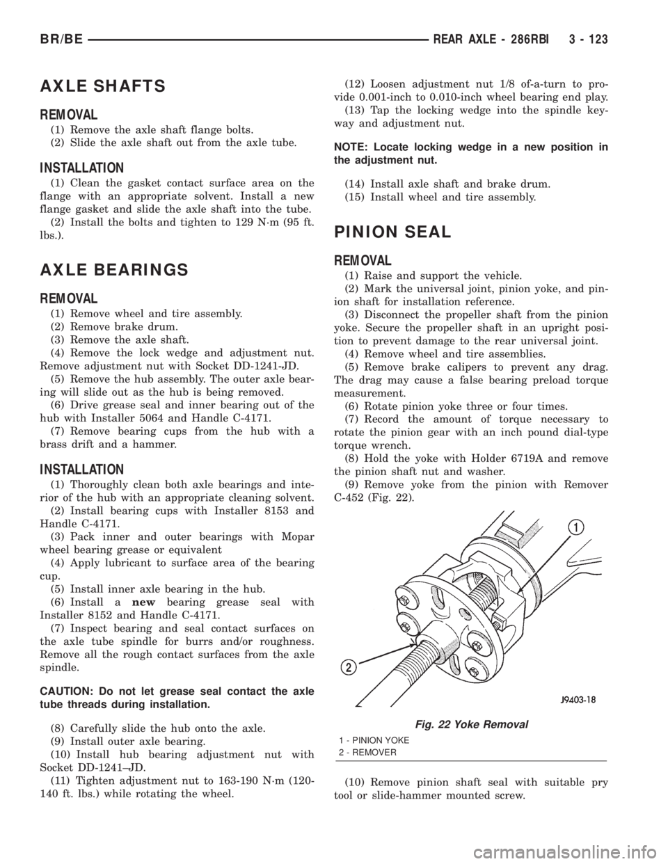
AXLE SHAFTS
REMOVAL
(1) Remove the axle shaft flange bolts.
(2) Slide the axle shaft out from the axle tube.
INSTALLATION
(1) Clean the gasket contact surface area on the
flange with an appropriate solvent. Install a new
flange gasket and slide the axle shaft into the tube.
(2) Install the bolts and tighten to 129 N´m (95 ft.
lbs.).
AXLE BEARINGS
REMOVAL
(1) Remove wheel and tire assembly.
(2) Remove brake drum.
(3) Remove the axle shaft.
(4) Remove the lock wedge and adjustment nut.
Remove adjustment nut with Socket DD-1241-JD.
(5) Remove the hub assembly. The outer axle bear-
ing will slide out as the hub is being removed.
(6) Drive grease seal and inner bearing out of the
hub with Installer 5064 and Handle C-4171.
(7) Remove bearing cups from the hub with a
brass drift and a hammer.
INSTALLATION
(1) Thoroughly clean both axle bearings and inte-
rior of the hub with an appropriate cleaning solvent.
(2) Install bearing cups with Installer 8153 and
Handle C-4171.
(3) Pack inner and outer bearings with Mopar
wheel bearing grease or equivalent
(4) Apply lubricant to surface area of the bearing
cup.
(5) Install inner axle bearing in the hub.
(6) Install anewbearing grease seal with
Installer 8152 and Handle C-4171.
(7) Inspect bearing and seal contact surfaces on
the axle tube spindle for burrs and/or roughness.
Remove all the rough contact surfaces from the axle
spindle.
CAUTION: Do not let grease seal contact the axle
tube threads during installation.
(8) Carefully slide the hub onto the axle.
(9) Install outer axle bearing.
(10) Install hub bearing adjustment nut with
Socket DD-1241±JD.
(11) Tighten adjustment nut to 163-190 N´m (120-
140 ft. lbs.) while rotating the wheel.(12) Loosen adjustment nut 1/8 of-a-turn to pro-
vide 0.001-inch to 0.010-inch wheel bearing end play.
(13) Tap the locking wedge into the spindle key-
way and adjustment nut.
NOTE: Locate locking wedge in a new position in
the adjustment nut.
(14) Install axle shaft and brake drum.
(15) Install wheel and tire assembly.
PINION SEAL
REMOVAL
(1) Raise and support the vehicle.
(2) Mark the universal joint, pinion yoke, and pin-
ion shaft for installation reference.
(3) Disconnect the propeller shaft from the pinion
yoke. Secure the propeller shaft in an upright posi-
tion to prevent damage to the rear universal joint.
(4) Remove wheel and tire assemblies.
(5) Remove brake calipers to prevent any drag.
The drag may cause a false bearing preload torque
measurement.
(6) Rotate pinion yoke three or four times.
(7) Record the amount of torque necessary to
rotate the pinion gear with an inch pound dial-type
torque wrench.
(8) Hold the yoke with Holder 6719A and remove
the pinion shaft nut and washer.
(9) Remove yoke from the pinion with Remover
C-452 (Fig. 22).
(10) Remove pinion shaft seal with suitable pry
tool or slide-hammer mounted screw.
Fig. 22 Yoke Removal
1 - PINION YOKE
2 - REMOVER
BR/BEREAR AXLE - 286RBI 3 - 123
Page 229 of 2255

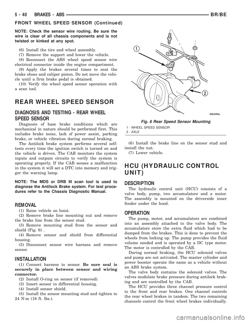
NOTE: Check the sensor wire routing. Be sure the
wire is clear of all chassis components and is not
twisted or kinked at any spot.
(6) Install the tire and wheel assembly.
(7) Remove the support and lower the vehicle.
(8) Reconnect the ABS wheel speed sensor wire
electrical connector inside the engine compartment.
(9) Apply the brakes several times to seat the
brake shoes and caliper piston. Do not move the vehi-
cle until a firm brake pedal is obtained.
(10) Verify the wheel speed sensor operation with
a scan tool.
REAR WHEEL SPEED SENSOR
DIAGNOSIS AND TESTING - REAR WHEEL
SPEED SENSOR
Diagnosis of base brake conditions which are
mechanical in nature should be performed first. This
includes brake noise, lack of power assist, parking
brake, or vehicle vibration during normal braking.
The Antilock brake system performs several self-
tests every time the ignition switch is turned on and
the vehicle is driven. The CAB monitors the system
inputs and outputs circuits to verify the system is
operating properly. If the CAB senses a malfunction
in the system it will set a DTC into memory and trig-
ger the warning lamp.
NOTE: The MDS or DRB III scan tool is used to
diagnose the Antilock Brake system. For test proce-
dures refer to the Chassis Diagnostic Manual.
REMOVAL
(1) Raise vehicle on hoist.
(2) Remove brake line mounting nut and remove
the brake line from the sensor stud.
(3) Remove mounting stud from the sensor and
shield (Fig. 6) .
(4) Remove sensor and shield from differential
housing.
(5) Disconnect sensor wire harness and remove
sensor.
INSTALLATION
(1) Connect harness to sensor.Be sure seal is
securely in place between sensor and wiring
connector.
(2) Install O-ring on sensor (if removed).
(3) Insert sensor in differential housing.
(4) Install sensor shield.
(5) Install the sensor mounting stud and tighten to
24 N´m (18 ft. lbs.).(6) Install the brake line on the sensor stud and
install the nut.
(7) Lower vehicle.
HCU (HYDRAULIC CONTROL
UNIT)
DESCRIPTION
The hydraulic control unit (HCU) consists of a
valve body, pump, two accumulators and a motor.
The assembly is mounted on the driverside inner
fender under the hood.
OPERATION
The pump, motor, and accumulators are combined
into an assembly attached to the valve body. The
accumulators store the extra fluid which had to be
dumped from the brakes. This is done to prevent the
wheels from locking up. The pump provides the fluid
volume needed and is operated by a DC type motor.
The motor is controlled by the CAB.
During normal braking, the HCU solenoid valves
and pump are not activated. The master cylinder and
power booster operate the same as a vehicle without
an ABS brake system.
The valve body contains the solenoid valves. The
valves modulate brake pressure during antilock brak-
ing and are controlled by the CAB.
The HCU provides three channel pressure control
to the front and rear brakes. One channel controls
the rear wheel brakes in tandem. The two remaining
channels control the front wheel brakes individually.
Fig. 6 Rear Speed Sensor Mounting
1 - WHEEL SPEED SENSOR
2 - AXLE
5 - 40 BRAKES - ABSBR/BE
FRONT WHEEL SPEED SENSOR (Continued)
Page 368 of 2255

CTM through the use of a combination of soldered
splices, splice block connectors, and many different
types of wire harness terminal connectors and insu-
lators. Refer to the appropriate wiring information.
The wiring information includes wiring diagrams,
proper wire and connector repair procedures, further
details on wire harness routing and retention, as well
as pin-out and location views for the various wire
harness connectors, splices and grounds.
All versions of the CTM for this model are serviced
only as a complete unit. Many of the electronic fea-
tures in the vehicle controlled or supported by the
high-line or premium versions of the CTM are pro-
grammable using the DRBIIItscan tool.However, if
any of the CTM hardware components are damaged
or faulty, the entire CTM unit must be replaced. The
base version of the CTM and the hard wired inputs
or outputs of all CTM versions can be diagnosed
using conventional diagnostic tools and methods;
however, for diagnosis of the high-line or premium
versions of the CTM or the CCD data bus, the use of
a DRBIIItscan tool is required. Refer to the appro-
priate diagnostic information.
OPERATION
The Central Timer Module (CTM) is designed to
control and integrate many of the electronic features
and functions of the vehicle. The base version of the
CTM monitors only hard wired inputs and responds
with the proper hard wired outputs. The microproces-
sor-based high-line/premium version of the CTM
monitors many hard wired switch and sensor inputs
as well as those resources it shares with other elec-
tronic modules in the vehicle through its communica-
tion over the Chrysler Collision Detection (CCD) data
bus network. The internal programming and all of
these inputs allow the high-line/premium CTM
microprocessor to determine the tasks it needs to
perform and their priorities, as well as both the stan-
dard and optional features that it should provide.
The high-line/premium CTM programming then per-
forms those tasks and provides those features
through both CCD data bus communication with
other electronic modules and through hard wired out-
puts to a number of circuits, relays, and actuators.
These outputs allow the high-line/premium CTM the
ability to control numerous accessory systems in the
vehicle.
All versions of the CTM operate on battery current
received through fuses in the Junction Block (JB) on
a non-switched fused B(+) circuit, a fused ignition
switch output (st-run) circuit (base version only), and
a fused ignition switch output (run-acc) circuit (high-
line/premium version only). This arrangement allows
the CTM to provide some features regardless of the
ignition switch position, while other features willoperate only with the ignition switch in the Acces-
sory, On, and/or Start positions. All versions of the
CTM are grounded through their connector and take
out of the instrument panel wire harness. The high-
line/premium CTM has another ground received
through a second connector and take out of the
instrument panel wire harness. The first ground cir-
cuit receives ground through a take out with an eye-
let terminal connector of the instrument panel wire
harness that is secured by a nut to a ground stud
located on the left instrument panel end bracket,
while the second ground circuit (high-line/premium
version only) receives ground through a take out with
an eyelet terminal connector of the instrument panel
wire harness that is secured by a nut to a ground
stud located on the back of the instrument panel
armature above the inboard side of the instrument
panel steering column opening.
The high-line/premium CTM monitors its own
internal circuitry as well as many of its input and
output circuits, and will store a Diagnostic Trouble
Code (DTC) in electronic memory for any failure it
detects. These DTCs can be retrieved and diagnosed
using a DRBIIItscan tool. Refer to the appropriate
diagnostic information.
HARD WIRED INPUTS
The hard wired inputs to the CTM include the fol-
lowing:
²CCD bus± - high-line/premium version only
²CCD bus+ - high-line/premium version only
²Cylinder lock switch mux - high-line premium
version only
²Driver door ajar switch sense
²Fused B(+)
²Fused ignition switch output (run-acc) - high-
line/premium version only
²Fused ignition switch output (st-run) - base ver-
sion only
²Ground (one circuit - base version, two circuits -
high-line/premium version)
²Key-in ignition switch sense
²Passenger door ajar switch sense - high-line/pre-
mium version only
²Power door lock motor B(+) lock - high-line/pre-
mium version only
²Power door lock motor B(+) unlock - high-line/
premium version only
²Radio control mux - high-line/premium version
only
²Tone request signal
²Washer switch sense
²Wiper park switch sense
²Wiper switch mode sense
²Wiper switch mode signal
BR/BEELECTRONIC CONTROL MODULES 8E - 3
CENTRAL TIMER MODULE (Continued)