2002 DODGE RAM battery capacity
[x] Cancel search: battery capacityPage 399 of 2255
²Temperature- A longer time will be needed to
charge a battery at -18É C (0É F) than at 27É C (80É
F). When a fast battery charger is connected to a cold
battery, the current accepted by the battery will be
very low at first. As the battery warms, it will accept
a higher charging current rate (amperage).
²Charger Capacity- A battery charger that
supplies only five amperes will require a longer
charging time. A battery charger that supplies
twenty amperes or more will require a shorter charg-
ing time.
²State-Of-Charge- A completely discharged bat-
tery requires more charging time than a partially
discharged battery. Electrolyte is nearly pure water
in a completely discharged battery. At first, the
charging current (amperage) will be low. As the bat-
tery charges, the specific gravity of the electrolyte
will gradually rise.
The Battery Charging Time Table gives an indica-
tion of the time required to charge a typical battery
at room temperature based upon the battery state-of-
charge and the charger capacity.
BATTERY CHARGING TIME TABLE
Charging
Amperage5 Amps10
Amps20 Amps
Open Circuit
VoltageHours Charging @
21É C (70É F)
12.25 to 12.49 6 hours 3 hours 1.5
hours
12.00 to 12.24 10 hours 5 hours 2.5
hours
10.00 to 11.99 14 hours 7 hours 3.5
hours
Below 10.00 18 hours 9 hours 4.5
hours
STANDARD PROCEDURE - BUILT-IN
INDICATOR TEST
An indicator (hydrometer) built into the top of the
battery case provides visual information for battery
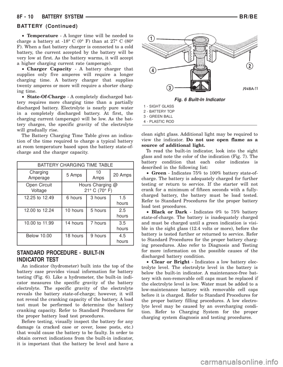
testing (Fig. 6). Like a hydrometer, the built-in indi-
cator measures the specific gravity of the battery
electrolyte. The specific gravity of the electrolyte
reveals the battery state-of-charge; however, it will
not reveal the cranking capacity of the battery. A load
test must be performed to determine the battery
cranking capacity. Refer to Standard Procedures for
the proper battery load test procedures.
Before testing, visually inspect the battery for any
damage (a cracked case or cover, loose posts, etc.)
that would cause the battery to be faulty. In order to
obtain correct indications from the built-in indicator,
it is important that the battery be level and have aclean sight glass. Additional light may be required to
view the indicator.Do not use open flame as a
source of additional light.
To read the built-in indicator, look into the sight
glass and note the color of the indication (Fig. 7). The
battery condition that each color indicates is
described in the following list:
²Green- Indicates 75% to 100% battery state-of-
charge. The battery is adequately charged for further
testing or return to service. If the starter will not
crank for a minimum of fifteen seconds with a fully-
charged battery, the battery must be load tested.
Refer to Standard Procedures for the proper battery
load test procedures.
²Black or Dark- Indicates 0% to 75% battery
state-of-charge. The battery is inadequately charged
and must be charged until a green indication is visi-
ble in the sight glass (12.4 volts or more), before the
battery is tested further or returned to service. Refer
to Standard Procedures for the proper battery charg-
ing procedures. Also refer to Diagnosis and Testing
for more information on the possible causes of the
discharged battery condition.
²Clear or Bright- Indicates a low battery elec-
trolyte level. The electrolyte level in the battery is
below the built-in indicator. A maintenance-free bat-
tery with non-removable cell caps must be replaced if
the electrolyte level is low. Water must be added to a
low-maintenance battery with removable cell caps
before it is charged. Refer to Standard Procedures for
the proper battery filling procedures. A low electro-
lyte level may be caused by an overcharging condi-
tion. Refer to Charging System for the proper
charging system diagnosis and testing procedures.
Fig. 6 Built-In Indicator
1 - SIGHT GLASS
2 - BATTERY TOP
3 - GREEN BALL
4 - PLASTIC ROD
8F - 10 BATTERY SYSTEMBR/BE
BATTERY (Continued)
Page 401 of 2255

Test the specific gravity of the electrolyte in each
battery cell. If the specific gravity of all cells is above
1.235, but the variation between cells is more than
fifty points (0.050), the battery should be replaced. If
the specific gravity of one or more cells is less than
1.235, charge the battery at a rate of approximately
five amperes. Continue charging the battery until
three consecutive specific gravity tests, taken at one-
hour intervals, are constant. If the cell specific grav-
ity variation is more than fifty points (0.050) at the
end of the charge period, replace the battery.
When the specific gravity of all cells is above 1.235,
and the cell variation is less than fifty points (0.050),
the battery may be load tested to determine its
cranking capacity. Refer to Standard Procedures for
the proper battery load test procedures.
STANDARD PROCEDURE - OPEN-CIRCUIT
VOLTAGE TEST
A battery open-circuit voltage (no load) test will
show the approximate state-of-charge of a battery.
This test can be used in place of the hydrometer test
when a hydrometer is not available, or for mainte-
nance-free batteries with non-removable cell caps.
Before proceeding with this test, completely charge
the battery (Refer to 8 - ELECTRICAL/BATTERY
SYSTEM/BATTERY - STANDARD PROCEDURE).
(1) Before measuring the open-circuit voltage, the
surface charge must be removed from the battery.
Turn on the headlamps for fifteen seconds, then
allow up to five minutes for the battery voltage to
stabilize.
(2) Disconnect and isolate both battery cables, neg-
ative cable first.
(3) Using a voltmeter connected to the battery
posts (see the instructions provided by the manufac-
turer of the voltmeter), measure the open-circuit volt-
age (Fig. 9).See the Open-Circuit Voltage Table. This voltage
reading will indicate the battery state-of-charge, but
will not reveal its cranking capacity. If a battery has
an open-circuit voltage reading of 12.4 volts or
greater, it may be load tested to reveal its cranking
capacity (Refer to 8 - ELECTRICAL/BATTERY SYS-
TEM/BATTERY - STANDARD PROCEDURE).
OPEN CIRCUIT VOLTAGE TABLE
Open Circuit Voltage Charge Percentage
11.7 volts or less 0%
12.0 volts 25%
12.2 volts 50%
12.4 volts 75%
12.6 volts or more 100%
STANDARD PROCEDURE - LOAD TEST
A battery load test will verify the battery cranking
capacity. The test is based on the Cold Cranking
Amperage (CCA) rating of the battery. To determine
the battery CCA rating, see the label affixed to the
battery case or refer to Battery Specifications for the
proper factory-installed specifications.
Before proceeding with this test, completely charge
the battery (Refer to 8 - ELECTRICAL/BATTERY
SYSTEM/BATTERY - STANDARD PROCEDURE).
(1) Disconnect and isolate both battery cables, neg-
ative cable first. The battery top and posts should be
clean (Refer to 8 - ELECTRICAL/BATTERY SYSTEM
- CLEANING).
(2) Connect a suitable volt-ammeter-load tester
(Fig. 10) to the battery posts (Fig. 11). See the
instructions provided by the manufacturer of the
tester you are using. Check the open-circuit voltage
(no load) of the battery (Refer to 8 - ELECTRICAL/
BATTERY SYSTEM/BATTERY - STANDARD PRO-
CEDURE). The battery open-circuit voltage must be
12.4 volts or greater.
Fig. 9 Testing Open-Circuit Voltage - Typical
Fig. 10 Volt-Ammeter-Load Tester - Typical
8F - 12 BATTERY SYSTEMBR/BE
BATTERY (Continued)
Page 407 of 2255

(5) Remove the battery hold down strap from the
top of the battery case.
INSTALLATION
(1) Clean and inspect the battery hold down hard-
ware (Refer to 8 - ELECTRICAL/BATTERY SYSTEM
- CLEANING).
(2) Position the battery hold down strap across the
top of the battery case.
(3) Install and tighten the two battery hold down
bolts through the holes on each end of the hold down
strap and into the U-nuts on each side of the battery
tray. Tighten the bolts to 4 N´m (35 in. lbs.).
(4) Reconnect the battery negative cable terminal
clamp to the battery negative terminal post. Tighten
the terminal clamp pinch-bolt hex nut to 4 N´m (35
in. lbs.).
BATTERY CABLE
DESCRIPTION
The battery cables (Fig. 19) are large gauge,
stranded copper wires sheathed within a heavy plas-
tic or synthetic rubber insulating jacket. The wire
used in the battery cables combines excellent flexibil-
ity and reliability with high electrical current carry-
ing capacity. Refer toWiring Diagramsfor the
location of the proper battery cable wire gauge infor-
mation.The battery cables cannot be repaired and, if dam-
aged or faulty they must be replaced. Both the bat-
tery positive and negative cables are available for
service replacement only as a unit with the battery
positive cable wire harness or the battery negative
cable wire harness, which may include portions of
the wiring circuits for the generator and other com-
ponents on some models.
GASOLINE ENGINE BATTERY CABLES
Gasoline engine models feature a stamped brass
clamping type female battery terminal crimped onto
one end of the battery cable wire and then solder-
dipped. A square headed pinch-bolt and hex nut are
installed at the open end of the female battery termi-
nal clamp. The battery positive cable also includes a
red molded rubber protective cover for the female
battery terminal clamp. Large eyelet type terminals
are crimped onto the opposite end of the battery
cable wire and then solder-dipped. The battery posi-
tive cable wires have a red insulating jacket to pro-
vide visual identification and feature a larger female
battery terminal clamp to allow connection to the
larger battery positive terminal post. The battery
negative cable wires have a black insulating jacket
and a smaller female battery terminal clamp.
DIESEL ENGINE BATTERY CABLES
Diesel engine models feature a clamping type
female battery terminal made of soft lead die cast
onto one end of the battery cable wire. A square
headed pinch-bolt and hex nut are installed at the
open end of the female battery terminal clamp. The
pinch-bolt on the left side battery positive cable
female terminal clamp also has a stud extending
from the head of the bolt. Large eyelet type terminals
are crimped onto the opposite end of the battery
cable wire and then solder-dipped. The battery posi-
tive cable wires have a red insulating jacket to pro-
vide visual identification and feature a larger female
battery terminal clamp to allow connection to the
larger battery positive terminal post. The battery
negative cable wires have a black insulating jacket
and a smaller female battery terminal clamp.
OPERATION
The battery cables connect the battery terminal
posts to the vehicle electrical system. These cables
also provide a return path for electrical current gen-
erated by the charging system for restoring the volt-
age potential of the battery. The female battery
terminal clamps on the ends of the battery cable
wires provide a strong and reliable connection of the
battery cable to the battery terminal posts. The ter-
minal pinch bolts allow the female terminal clamps
to be tightened around the male terminal posts on
Fig. 19 Battery Cables - Typical
1 - EYELET
2 - NUT
3 - POWER DISTRIBUTION CENTER
4 - POSITIVE CABLE
5 - SCREW
6 - NEGATIVE CABLE
7 - EYELET
8 - CLIP
8F - 18 BATTERY SYSTEMBR/BE
BATTERY HOLDDOWN (Continued)
Page 422 of 2255
Starting System Diagnosis
CONDITION POSSIBLE CAUSE CORRECTION
STARTER ENGAGES,
SPINS OUT BEFORE
ENGINE STARTS.1. Starter ring gear faulty. 1. Refer to Starter Motor Removal and Installation.
Remove starter motor to inspect starter ring gear.
Replace starter ring gear if required.
2. Starter motor faulty. 2. If all other starting system components and circuits test
OK, replace starter motor assembly.
STARTER DOES NOT
DISENGAGE.1. Starter motor
improperly installed.1. Refer to Starter Motor Removal and Installation.
Tighten starter mounting hardware to correct torque
specifications.
2. Starter relay faulty. 2. Refer to Starter Relay Diagnosis and Testing. Replace
starter relay if required.
3. Ignition switch faulty. 3. Refer to Ignition Switch and Key Lock Cylinder.
Replace ignition switch if required.
4. Starter motor faulty. 4. If all other starting system components and circuits test
OK, replace starter motor.
INSPECTION
For complete starter wiring circuit diagrams, refer
to 8, Wiring Diagrams. Before removing any unit
from starting system for repair or diagnosis, perform
the following inspections:
WARNING: ON VEHICLES EQUIPPED WITH AIR-
BAGS, REFER TO 8, PASSIVE RESTRAINT SYS-
TEMS, BEFORE ATTEMPTING ANY STEERING
WHEEL, STEERING COLUMN, OR INSTRUMENT
PANEL COMPONENT DIAGNOSIS OR SERVICE.
FAILURE TO TAKE THE PROPER PRECAUTIONS
COULD RESULT IN ACCIDENTAL AIRBAG DEPLOY-
MENT AND POSSIBLE PERSONAL INJURY.
²Battery- Visually inspect battery for indica-
tions of physical damage and loose or corroded cable
connections. Determine state-of-charge and cranking
capacity of battery. Charge or replace battery if
required. Refer toBatteryin 8, Battery.Note: If
equipped with diesel engine, a dual battery sys-
tem may be used, and both batteries must be
inspected.
²Ignition Switch- Visually inspect ignition
switch for indications of physical damage and loose
or corroded wire harness connections. Refer toIgni-
tion Switch and Key Lock Cylinder.
²Clutch Pedal Position Switch- If equipped
with manual transmission, visually inspect clutch
pedal position switch for indications of physical dam-
age and loose or corroded wire harness connections.
Refer toClutch Pedal Position Switchin 6,
Clutch.
²Park/Neutral Position Switch- If equipped
with automatic transmission, visually inspect park/
neutral position switch for indications of physical
damage and loose or corroded wire harness connec-tions. Refer toPark/Neutral Position Switchin
21, Transmission.
²Starter Relay- Visually inspect starter relay
for indications of physical damage and loose or cor-
roded wire harness connections.
²Starter Motor- Visually inspect starter motor
for indications of physical damage and loose or cor-
roded wire harness connections.
²Starter Solenoid- Visually inspect starter sole-
noid for indications of physical damage and loose or
corroded wire harness connections.
²Wiring- Visually inspect wire harnesses for
damage. Repair or replace any faulty wiring, as
required. Refer to 8, Wiring Diagrams.
TESTING
COLD CRANKING TEST
For complete starter wiring circuit diagrams, refer
to 8, Wiring Diagrams. The battery must be fully-
charged and load-tested before proceeding. Refer to
Batteryin 8, Battery.
(1) Connect volt-ampere tester to battery terminals
(Fig. 1). See instructions provided by manufacturer of
volt-ampere tester being used.Note: Certain diesel
equipped models use dual batteries. If equipped
with dual battery system, tester should be con-
nected to battery on left side of vehicle only.
Also, tester current reading must be taken from
positive battery cable lead that connects to
starter motor.
(2) Fully engage parking brake.
(3) If equipped with manual transmission, place
gearshift selector lever in Neutral position and block
clutch pedal in fully depressed position. If equipped
with automatic transmission, place gearshift selector
lever in Park position.
BR/BESTARTING 8F - 33
STARTING (Continued)
Page 445 of 2255
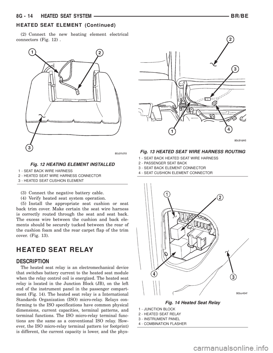
(2) Connect the new heating element electrical
connectors (Fig. 12) .
(3) Connect the negative battery cable.
(4) Verify heated seat system operation.
(5) Install the appropriate seat cushion or seat
back trim cover. Make certain the seat wire harness
is correctly routed through the seat and seat back.
The excess wire between the cushion and back ele-
ments should be securely tucked between the rear of
the cushion foam and the rear carpet flap of the trim
cover. (Fig. 13).
HEATED SEAT RELAY
DESCRIPTION
The heated seat relay is an electromechanical device
that switches battery current to the heated seat module
when the relay control coil is energized. The heated seat
relay is located in the Junction Block (JB), on the left
end of the instrument panel in the passenger compart-
ment (Fig. 14). The heated seat relay is a International
Standards Organization (ISO) micro-relay. Relays con-
forming to the ISO specifications have common physical
dimensions, current capacities, terminal patterns, and
terminal functions. The ISO micro-relay terminal func-
tions are the same as a conventional ISO relay. How-
ever, the ISO micro-relay terminal pattern (or footprint)
is different, the current capacity is lower, and the phys-
Fig. 12 HEATING ELEMENT INSTALLED
1 - SEAT BACK WIRE HARNESS
2 - HEATED SEAT WIRE HARNESS CONNECTOR
3 - HEATED SEAT CUSHION ELEMENT
Fig. 13 HEATED SEAT WIRE HARNESS ROUTING
1 - SEAT BACK HEATED SEAT WIRE HARNESS
2 - PASSENGER SEAT BACK
3 - SEAT BACK ELEMENT CONNECTOR
4 - SEAT CUSHION ELEMENT CONNECTOR
Fig. 14 Heated Seat Relay
1 - JUNCTION BLOCK
2 - HEATED SEAT RELAY
3 - INSTRUMENT PANEL
4 - COMBINATION FLASHER
8G - 14 HEATED SEAT SYSTEMBR/BE
HEATED SEAT ELEMENT (Continued)
Page 454 of 2255

INSTALLATION
(1) Position the horn and mounting bracket unit(s)
onto the right fender wheel house front extension.
(2) Install and tighten the screw that secures the
horn and mounting bracket unit(s) to the right
fender wheel house front extension. Tighten the
screw to 11 N´m (95 in. lbs.).
(3) Reconnect the wire harness connector(s) to the
horn connector receptacle(s).
(4) Reconnect the battery negative cable.
HORN RELAY
DESCRIPTION
The horn relay is a electromechanical device that
switches battery current to the horn when the horn
switch grounds the relay coil. The horn relay is
located in the Power Distribution Center (PDC) in
the engine compartment. If a problem is encountered
with a continuously sounding horn, it can usually be
quickly resolved by removing the horn relay from the
PDC until further diagnosis is completed. See the
fuse and relay layout label affixed to the inside sur-
face of the PDC cover for horn relay identification
and location.
The horn relay is a International Standards Orga-
nization (ISO) micro-relay. Relays conforming to the
ISO specifications have common physical dimensions,
current capacities, terminal patterns, and terminal
functions. The ISO micro-relay terminal functions
are the same as a conventional ISO relay. However,
the ISO micro-relay terminal pattern (or footprint) is
different, the current capacity is lower, and the phys-
ical dimensions are smaller than those of the conven-
tional ISO relay.
The horn relay cannot be repaired or adjusted and,
if faulty or damaged, it must be replaced.
OPERATION
The ISO relay consists of an electromagnetic coil, a
resistor or diode, and three (two fixed and one mov-
able) electrical contacts. The movable (common feed)
relay contact is held against one of the fixed contacts
(normally closed) by spring pressure. When the elec-
tromagnetic coil is energized, it draws the movable
contact away from the normally closed fixed contact,
and holds it against the other (normally open) fixed
contact.
When the electromagnetic coil is de-energized,
spring pressure returns the movable contact to the
normally closed position. The resistor or diode is con-
nected in parallel with the electromagnetic coil in the
relay, and helps to dissipate voltage spikes that are
produced when the coil is de-energized.
DIAGNOSIS AND TESTING - HORN RELAY
The horn relay (Fig. 2) is located in the Power Dis-
tribution Center (PDC) behind the battery on the
driver side of the engine compartment. If a problem
is encountered with a continuously sounding horn, it
can usually be quickly resolved by removing the horn
relay from the PDC until further diagnosis is com-
pleted. See the fuse and relay layout label affixed to
the inside surface of the PDC cover for horn relay
identification and location. For complete circuit dia-
grams, refer to the appropriate wiring information.
The wiring information includes wiring diagrams,
proper wire and connector repair procedures, details
of wire harness routing and retention, connector pin-
out information and location views for the various
wire harness connectors, splices and grounds.
WARNING: ON VEHICLES EQUIPPED WITH AIR-
BAGS, REFER TO ELECTRICAL, RESTRAINTS
BEFORE ATTEMPTING ANY STEERING WHEEL,
STEERING COLUMN, OR INSTRUMENT PANEL
COMPONENT DIAGNOSIS OR SERVICE. FAILURE
TO TAKE THE PROPER PRECAUTIONS COULD
RESULT IN ACCIDENTAL AIRBAG DEPLOYMENT
AND POSSIBLE PERSONAL INJURY.
(1) Remove the horn relay from the PDC. (Refer to
8 - ELECTRICAL/HORN/HORN RELAY -
REMOVAL) for the procedures.
(2) A relay in the de-energized position should
have continuity between terminals 87A and 30, and
no continuity between terminals 87 and 30. If OK, go
to Step 3. If not OK, replace the faulty relay.
(3) Resistance between terminals 85 and 86 (elec-
tromagnet) should be 75 5 ohms. If OK, go to Step
4. If not OK, replace the faulty relay.
(4) Connect a battery to terminals 85 and 86.
There should now be continuity between terminals
30 and 87, and no continuity between terminals 87A
and 30. If OK, perform the Relay Circuit Test that
follows. If not OK, replace the faulty relay.
RELAY CIRCUIT TEST
(1) The relay common feed terminal cavity (30) is
connected to battery voltage and should be hot at all
times. If OK, go to Step 2. If not OK, repair the open
circuit to the fuse in the PDC as required.
(2) The relay normally closed terminal (87A) is
connected to terminal 30 in the de-energized position,
but is not used for this application. Go to Step 3.
(3) The relay normally open terminal (87) is con-
nected to the common feed terminal (30) in the ener-
gized position. This terminal supplies battery voltage
to the horn(s). There should be continuity between
the cavity for relay terminal 87 and the horn relay
output circuit cavity of each horn wire harness con-
BR/BEHORN 8H - 3
HORN (Continued)
Page 1071 of 2255
(4) Press firmly on the cigar lighter or power out-
let receptacle base until the retaining bosses of the
mount are fully engaged in their receptacles.
(5) Install the cigar lighter knob and element into
the cigar lighter receptacle base, or the protective cap
into the power outlet receptacle base.
(6) Reconnect the battery negative cable.
HORN RELAY
DESCRIPTION
The horn relay is a International Standards Orga-
nization (ISO) micro-relay. The terminal designations
and functions are the same as a conventional ISO
relay. However, the micro-relay terminal orientation
(or footprint) is different, current capacity is lower,
and the relay case dimensions are smaller than those
of the conventional ISO relay.
The horn relay is a electromechanical device that
switches battery current to the horn when the horn
switch or when the high-line or premium Central
Timer Module (CTM) grounds the relay coil. See
Horn Relay in the Diagnosis and Testing section of
this group for more information.
The horn relay is located in the Power Distribution
Center (PDC), in the engine compartment. Refer to
the PDC label for relay identification and location.
If a problem is encountered with a continuously
sounding horn, it can usually be quickly resolved by
removing the horn relay from the PDC until further
diagnosis is completed.
The horn relay cannot be repaired and, if faulty or
damaged, it must be replaced.
DIAGNOSIS AND TESTING - HORN RELAY
The headlamp (or security) relay and the horn
relay are located in the Power Distribution Center
(PDC) in the engine compartment. Each of these
relays can be tested as described in the following pro-
cedure, however the circuits they are used in do vary.
To test the relay circuits, refer to the circuit descrip-
tions and diagrams in Wiring Diagrams.
WARNING: ON VEHICLES EQUIPPED WITH AIR-
BAGS, REFER TO THE RESTRAINTS SECTION OF
THE SERVICE MANUAL BEFORE ATTEMPTING ANY
STEERING WHEEL, STEERING COLUMN, OR
INSTRUMENT PANEL COMPONENT DIAGNOSIS OR
SERVICE. FAILURE TO TAKE THE PROPER PRE-
CAUTIONS COULD RESULT IN ACCIDENTAL AIR-
BAG DEPLOYMENT AND POSSIBLE PERSONAL
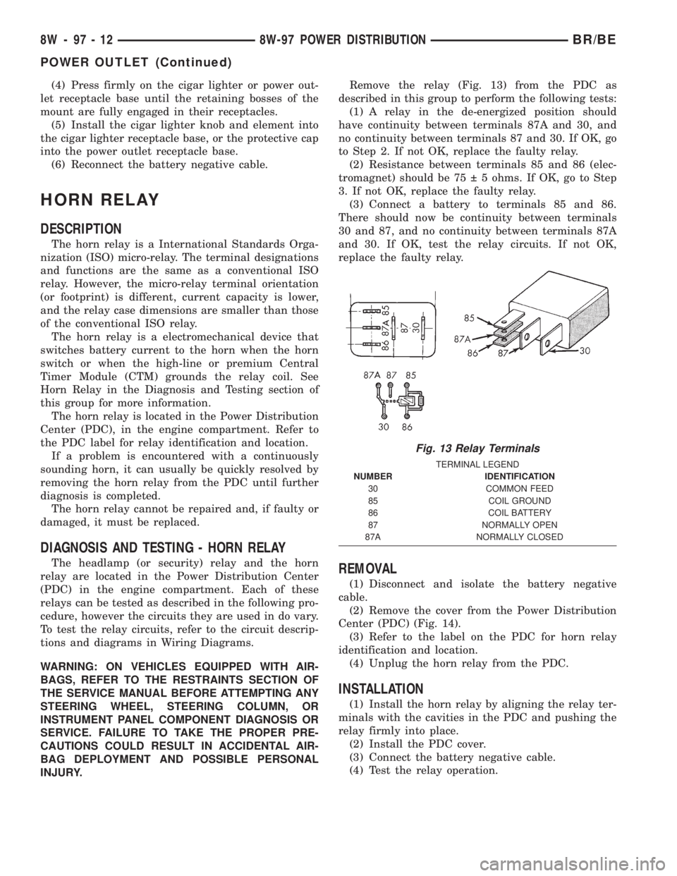
INJURY.Remove the relay (Fig. 13) from the PDC as
described in this group to perform the following tests:
(1) A relay in the de-energized position should
have continuity between terminals 87A and 30, and
no continuity between terminals 87 and 30. If OK, go
to Step 2. If not OK, replace the faulty relay.
(2) Resistance between terminals 85 and 86 (elec-
tromagnet) should be 75 5 ohms. If OK, go to Step
3. If not OK, replace the faulty relay.
(3) Connect a battery to terminals 85 and 86.
There should now be continuity between terminals
30 and 87, and no continuity between terminals 87A
and 30. If OK, test the relay circuits. If not OK,
replace the faulty relay.REMOVAL
(1) Disconnect and isolate the battery negative
cable.
(2) Remove the cover from the Power Distribution
Center (PDC) (Fig. 14).
(3) Refer to the label on the PDC for horn relay
identification and location.
(4) Unplug the horn relay from the PDC.
INSTALLATION
(1) Install the horn relay by aligning the relay ter-
minals with the cavities in the PDC and pushing the
relay firmly into place.
(2) Install the PDC cover.
(3) Connect the battery negative cable.
(4) Test the relay operation.
Fig. 13 Relay Terminals
TERMINAL LEGEND
NUMBER IDENTIFICATION
30 COMMON FEED
85 COIL GROUND
86 COIL BATTERY
87 NORMALLY OPEN
87A NORMALLY CLOSED
8W - 97 - 12 8W-97 POWER DISTRIBUTIONBR/BE
POWER OUTLET (Continued)
Page 1072 of 2255
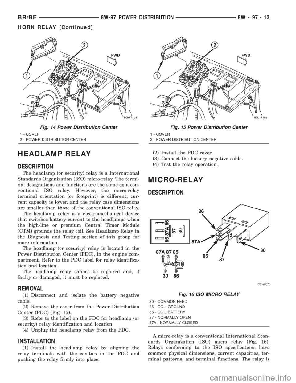
HEADLAMP RELAY
DESCRIPTION
The headlamp (or security) relay is a International
Standards Organization (ISO) micro-relay. The termi-
nal designations and functions are the same as a con-
ventional ISO relay. However, the micro-relay
terminal orientation (or footprint) is different, cur-
rent capacity is lower, and the relay case dimensions
are smaller than those of the conventional ISO relay.
The headlamp relay is a electromechanical device
that switches battery current to the headlamps when
the high-line or premium Central Timer Module
(CTM) grounds the relay coil. See Headlamp Relay in
the Diagnosis and Testing section of this group for
more information.
The headlamp (or security) relay is located in the
Power Distribution Center (PDC), in the engine com-
partment. Refer to the PDC label for relay identifica-
tion and location.
The headlamp relay cannot be repaired and, if
faulty or damaged, it must be replaced.
REMOVAL
(1) Disconnect and isolate the battery negative
cable.
(2) Remove the cover from the Power Distribution
Center (PDC) (Fig. 15).
(3) Refer to the label on the PDC for headlamp (or
security) relay identification and location.
(4) Unplug the headlamp relay from the PDC.
INSTALLATION
(1) Install the headlamp relay by aligning the
relay terminals with the cavities in the PDC and
pushing the relay firmly into place.(2) Install the PDC cover.
(3) Connect the battery negative cable.
(4) Test the relay operation.
MICRO-RELAY
DESCRIPTION
A micro-relay is a conventional International Stan-
dards Organization (ISO) micro relay (Fig. 16).
Relays conforming to the ISO specifications have
common physical dimensions, current capacities, ter-
minal patterns, and terminal functions. The relay is
Fig. 14 Power Distribution Center
1 - COVER
2 - POWER DISTRIBUTION CENTER
Fig. 15 Power Distribution Center
1 - COVER
2 - POWER DISTRIBUTION CENTER
Fig. 16 ISO MICRO RELAY
30 - COMMON FEED
85 - COIL GROUND
86 - COIL BATTERY
87 - NORMALLY OPEN
87A - NORMALLY CLOSED
BR/BE8W-97 POWER DISTRIBUTION 8W - 97 - 13
HORN RELAY (Continued)