2002 DODGE RAM oil viscosity
[x] Cancel search: oil viscosityPage 17 of 2255

COOLANT PERFORMANCE
The required ethylene-glycol (antifreeze) and water
mixture depends upon climate and vehicle operating
conditions. The coolant performance of various mix-
tures follows:
Pure Water-Water can absorb more heat than a
mixture of water and ethylene-glycol. This is for pur-
pose of heat transfer only. Water also freezes at a
higher temperature and allows corrosion.
100 percent Ethylene-Glycol-The corrosion
inhibiting additives in ethylene-glycol need the pres-
ence of water to dissolve. Without water, additives
form deposits in system. These act as insulation
causing temperature to rise to as high as 149ÉC
(300ÉF). This temperature is hot enough to melt plas-
tic and soften solder. The increased temperature can
result in engine detonation. In addition, 100 percent
ethylene-glycol freezes at -22ÉC (-8ÉF).
50/50 Ethylene-Glycol and Water-Is the recom-
mended mixture, it provides protection against freez-
ing to -37ÉC (-34ÉF). The antifreeze concentration
must alwaysbe a minimum of 44 percent, year-
round in all climates. If percentage is lower, engine
parts may be eroded by cavitation. Maximum protec-
tion against freezing is provided with a 68 percent
antifreeze concentration, which prevents freezing
down to -67.7ÉC (-90ÉF). A higher percentage will
freeze at a warmer temperature. Also, a higher per-
centage of antifreeze can cause the engine to over-
heat because specific heat of antifreeze is lower than
that of water.
CAUTION: Richer antifreeze mixtures cannot be
measured with normal field equipment and can
cause problems associated with 100 percent ethyl-
ene-glycol.
COOLANT SELECTION AND ADDITIVES
NOTE: Refer to the vehicle's coolant bottle to iden-
tify HOAT or Non-HOAT coolant. Non-HOAT coolant
is green in color.
The use of aluminum cylinder blocks, cylinder
heads and water pumps requires special corrosion
protection. Only MopartAntifreeze/Coolant, 5
Year/100,000 Mile Formula (glycol base coolant with
corrosion inhibitors called HOAT, for Hybrid Organic
Additive Technology) is recommended. This coolant
offers the best engine cooling without corrosion when
mixed with 50% distilled water to obtain to obtain a
freeze point of -37ÉC (-35ÉF). If it loses color or
becomes contaminated, drain, flush, and replace with
fresh properly mixed coolant solution.CAUTION: Do not use coolant additives that are
claimed to improve engine cooling.
DESCRIPTIONÐENGINE OIL
API SERVICE GRADE CERTIFIED
WARNING: NEW OR USED ENGINE OIL CAN BE
IRRITATING TO THE SKIN. AVOID PROLONGED OR
REPEATED SKIN CONTACT WITH ENGINE OIL.
CONTAMINANTS IN USED ENGINE OIL, CAUSED BY
INTERNAL COMBUSTION, CAN BE HAZARDOUS TO
YOUR HEALTH. THOROUGHLY WASH EXPOSED
SKIN WITH SOAP AND WATER. DO NOT WASH
SKIN WITH GASOLINE, DIESEL FUEL, THINNER, OR
SOLVENTS, HEALTH PROBLEMS CAN RESULT. DO
NOT POLLUTE, DISPOSE OF USED ENGINE OIL
PROPERLY. CONTACT YOUR DEALER OR GOVERN-
MENT AGENCY FOR LOCATION OF COLLECTION
CENTER IN YOUR AREA.
Standard engine-oil identification notations have
been adopted to aid in the proper selection of engine
oil. The identifying notations are located on the label
of engine oil plastic bottles and the top of engine oil
cans.
In diesel engines, use an engine oil that conforms
to API Service Grade CF-4 or CG-4/SH (Fig. 3).
MOPARtprovides an engine oil that conforms to this
particular grade.
SAE VISCOSITY
An SAE viscosity grade is used to specify the vis-
cosity of engine oil. SAE 15W±40 specifies a multiple
viscosity engine oil.
When choosing an engine oil, consider the range of
temperatures the vehicle will be operated in before
the next oil change. Select an engine oil that is best
suited to your area's particular ambient temperature
range and variation. For diesel engines, refer to (Fig.
4).
Fig. 3 API Service Grade Certification LabelÐDiesel
Engine Oil
0 - 4 LUBRICATION & MAINTENANCEBR/BE
FLUID TYPES (Continued)
Page 18 of 2255

DESCRIPTION - ENGINE OIL
WARNING: NEW OR USED ENGINE OIL CAN BE
IRRITATING TO THE SKIN. AVOID PROLONGED OR
REPEATED SKIN CONTACT WITH ENGINE OIL.
CONTAMINANTS IN USED ENGINE OIL, CAUSED BY
INTERNAL COMBUSTION, CAN BE HAZARDOUS TO
YOUR HEALTH. THOROUGHLY WASH EXPOSED
SKIN WITH SOAP AND WATER. DO NOT WASH
SKIN WITH GASOLINE, DIESEL FUEL, THINNER, OR
SOLVENTS, HEALTH PROBLEMS CAN RESULT. DO
NOT POLLUTE, DISPOSE OF USED ENGINE OIL
PROPERLY. CONTACT YOUR DEALER OR GOVERN-
MENT AGENCY FOR LOCATION OF COLLECTION
CENTER IN YOUR AREA.
API SERVICE GRADE CERTIFIED
Use an engine oil that is API Service Grade Certi-
fied. MOPARtprovides engine oils that conform to
this service grade.
SAE VISCOSITY
An SAE viscosity grade is used to specify the vis-
cosity of engine oil. Use only engine oils with multi-
ple viscosities such as 5W-30 or 10W-30. These oils
are specified with a dual SAE viscosity grade which
indicates the cold-to-hot temperature viscosity range.
Select an engine oil that is best suited to your par-
ticular temperature range and variation (Fig. 5).
ENERGY CONSERVING OIL
An Energy Conserving type oil is recommended for
gasoline engines. The designation of ENERGY CON-
SERVING is located on the label of an engine oil con-
tainer.
CONTAINER IDENTIFICATION
Standard engine oil identification notations have
been adopted to aid in the proper selection of engine
oil. The identifying notations are located on the label
of engine oil plastic bottles and the top of engine oil
cans (Fig. 6).
DESCRIPTION - AXLE LUBRICATION
A multi-purpose, hypoid gear lubricant which con-
forms to the following specifications should be used.
Mopar Hypoid Gear Lubricant conforms to these
specifications.
NOTE: Trac-lokTand Powr-lokTequipped axles
require a friction modifier be added to the lubricant.
FRONT AXLE
²The lubricant should have MIL-L-2105C and
API GL 5 quality specifications.
²Lubricant is a thermally stable SAE 80W90.
REAR AXLE
²The lubricant should have MIL-L-2105C and
API GL 5 quality specifications.
²Lubricant is a thermally stable SAE 90W.
DESCRIPTION - TRANSFER CASE - NV241
Recommended lubricant for the NV241 transfer
case is MopartATF+4, type 9602, Automatic Trans-
mission Fluid.
DESCRIPTION - MANUAL TRANSMISSION
MopartManual Transmission Lubricant is recom-
mended or equivalent for use in the manual trans-
missions.
Fig. 4 Engine Oil Viscosity RecommendationÐ
Diesel Engines
Fig. 5 Temperature/Engine Oil Viscosity
Fig. 6 API Symbol
BR/BELUBRICATION & MAINTENANCE 0 - 5
FLUID TYPES (Continued)
Page 19 of 2255

DESCRIPTION - AUTOMATIC TRANSMISSION
FLUID
NOTE: Refer to the maintenance schedules in this
group for the recommended maintenance (fluid/filter
change) intervals for this transmission.
NOTE: Refer to Service Procedures in this group for
fluid level checking procedures.
MopartATF +4, type 9602, Automatic Transmis-
sion Fluid is the recommended fluid for
DaimlerChrysler automatic transmissions.
Dexron II fluid IS NOT recommended. Clutch
chatter can result from the use of improper
fluid.
MopartATF +4, type 9602, Automatic Transmis-
sion Fluid when new is red in color. The ATF is dyed
red so it can be identified from other fluids used in
the vehicle such as engine oil or antifreeze. The red
color is not permanent and is not an indicator of fluid
condition. As the vehicle is driven, the ATF will begin
to look darker in color and may eventually become
brown.This is normal.A dark brown/black fluid
accompanied with a burnt odor and/or deterioration
in shift quality may indicate fluid deterioration or
transmission component failure.
FLUID ADDITIVES
DaimlerChrysler strongly recommends against the
addition of any fluids to the transmission, other than
those automatic transmission fluids listed above.
Exceptions to this policy are the use of special dyes
to aid in detecting fluid leaks.
Various ªspecialº additives and supplements exist
that claim to improve shift feel and/or quality. These
additives and others also claim to improve converter
clutch operation and inhibit overheating, oxidation,
varnish, and sludge. These claims have not been sup-
ported to the satisfaction of DaimlerChrysler and
these additivesmust not be used.The use of trans-
mission ªsealersº should also be avoided, since they
may adversely affect the integrity of transmission
seals.
OPERATION - AUTOMATIC TRANSMISSION
FLUID
The automatic transmission fluid is selected based
upon several qualities. The fluid must provide a high
level of protection for the internal components by
providing a lubricating film between adjacent metal
components. The fluid must also be thermally stable
so that it can maintain a consistent viscosity through
a large temperature range. If the viscosity stays con-
stant through the temperature range of operation,transmission operation and shift feel will remain con-
sistent. Transmission fluid must also be a good con-
ductor of heat. The fluid must absorb heat from the
internal transmission components and transfer that
heat to the transmission case.
FLUID CAPACITIES
SPECIFICATIONS
FLUID CAPACITIES
DESCRIPTION SPECIFICATION
FUEL TANK
2500 Series Club Cab
and Quad Cab with 6.5'
Short Box129 L (34 gal.)*****
All 8' Long Box 132 L (35 gal.)*****
All Cab/Chassis Models 132 L (35 gal.)*****
ENGINE OIL WITH FILTER
5.9L 4.7 L (5.0 qts.)
8.0L 6.6 L (7.0 qts.)
5.9L DIESEL 10.4 L (11.0 qts.)
COOLING SYSTEM
5.9L 19 L (20 qts.)****
8.0L 24.5 L (26.0 qts.)****
5.9L DIESEL 22.7 L (24.0 qts.)****
POWER STEERING
Power steering fluid capacities are dependent on
engine/chassis options as well as steering gear/cooler
options. Depending on type and size of internal
cooler, length and inside diameter of cooler lines, or
use of an auxiliary cooler, these capacities may vary.
Refer to 19, Steering for proper fill and bleed
procedures.
AUTOMATIC TRANSMISSION
Service Fill - 46RE 3.8 L (4.0 qts.)
O-haul - 46RE 9-9.5L (19-20 pts.)*
Service Fill - 47RE 3.8 L (4.0 qts.)
O-haul - 47RE 14-16 L (29-33 pts.)*
0 - 6 LUBRICATION & MAINTENANCEBR/BE
FLUID TYPES (Continued)
Page 1081 of 2255
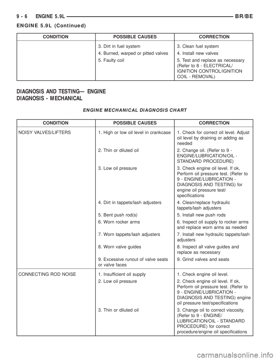
CONDITION POSSIBLE CAUSES CORRECTION
3. Dirt in fuel system 3. Clean fuel system
4. Burned, warped or pitted valves 4. Install new valves
5. Faulty coil 5. Test and replace as necessary
(Refer to 8 - ELECTRICAL/
IGNITION CONTROL/IGNITION
COIL - REMOVAL)
DIAGNOSIS AND TESTINGÐ ENGINE
DIAGNOSIS - MECHANICAL
ENGINE MECHANICAL DIAGNOSIS CHART
CONDITION POSSIBLE CAUSES CORRECTION
NOISY VALVES/LIFTERS 1. High or low oil level in crankcase 1. Check for correct oil level. Adjust
oil level by draining or adding as
needed
2. Thin or diluted oil 2. Change oil. (Refer to 9 -
ENGINE/LUBRICATION/OIL -
STANDARD PROCEDURE)
3. Low oil pressure 3. Check engine oil level. If ok,
Perform oil pressure test. (Refer to
9 - ENGINE/LUBRICATION -
DIAGNOSIS AND TESTING) for
engine oil pressure test/
specifications
4. Dirt in tappets/lash adjusters 4. Clean/replace hydraulic
tappets/lash adjusters
5. Bent push rod(s) 5. Install new push rods
6. Worn rocker arms 6. Inspect oil supply to rocker arms
and replace worn arms as needed
7. Worn tappets/lash adjusters 7. Install new hydraulic tappets/lash
adjusters
8. Worn valve guides 8. Inspect all valve guides and
replace as necessary
9. Excessive runout of valve seats
or valve faces9. Grind valves and seats
CONNECTING ROD NOISE 1. Insufficient oil supply 1. Check engine oil level.
2. Low oil pressure 2. Check engine oil level. If ok,
Perform oil pressure test. (Refer to
9 - ENGINE/LUBRICATION -
DIAGNOSIS AND TESTING) engine
oil pressure test/specifications
3. Thin or diluted oil 3. Change oil to correct viscosity.
(Refer to 9 - ENGINE/
LUBRICATION/OIL - STANDARD
PROCEDURE) for correct
procedure/engine oil specifications
9 - 6 ENGINE 5.9LBR/BE
ENGINE 5.9L (Continued)
Page 1082 of 2255
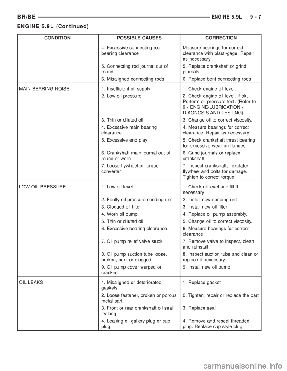
CONDITION POSSIBLE CAUSES CORRECTION
4. Excessive connecting rod
bearing clearanceMeasure bearings for correct
clearance with plasti-gage. Repair
as necessary
5. Connecting rod journal out of
round5. Replace crankshaft or grind
journals
6. Misaligned connecting rods 6. Replace bent connecting rods
MAIN BEARING NOISE 1. Insufficient oil supply 1. Check engine oil level.
2. Low oil pressure 2. Check engine oil level. If ok,
Perform oil pressure test. (Refer to
9 - ENGINE/LUBRICATION -
DIAGNOSIS AND TESTING)
3. Thin or diluted oil 3. Change oil to correct viscosity.
4. Excessive main bearing
clearance4. Measure bearings for correct
clearance. Repair as necessary
5. Excessive end play 5. Check crankshaft thrust bearing
for excessive wear on flanges
6. Crankshaft main journal out of
round or worn6. Grind journals or replace
crankshaft
7. Loose flywheel or torque
converter7. Inspect crankshaft, flexplate/
flywheel and bolts for damage.
Tighten to correct torque
LOW OIL PRESSURE 1. Low oil level 1. Check oil level and fill if
necessary
2. Faulty oil pressure sending unit 2. Install new sending unit
3. Clogged oil filter 3. Install new oil filter
4. Worn oil pump 4. Replace oil pump assembly.
5. Thin or diluted oil 5. Change oil to correct viscosity.
6. Excessive bearing clearance 6. Measure bearings for correct
clearance
7. Oil pump relief valve stuck 7. Remove valve to inspect, clean
and reinstall
8. Oil pump suction tube loose,
broken, bent or clogged8. Inspect suction tube and clean or
replace if necessary
9. Oil pump cover warped or
cracked9. Install new oil pump
OIL LEAKS 1. Misaligned or deteriorated
gaskets1. Replace gasket
2. Loose fastener, broken or porous
metal part2. Tighten, repair or replace the part
3. Front or rear crankshaft oil seal
leaking3. Replace seal
4. Leaking oil gallery plug or cup
plug4. Remove and reseal threaded
plug. Replace cup style plug
BR/BEENGINE 5.9L 9 - 7
ENGINE 5.9L (Continued)
Page 1136 of 2255
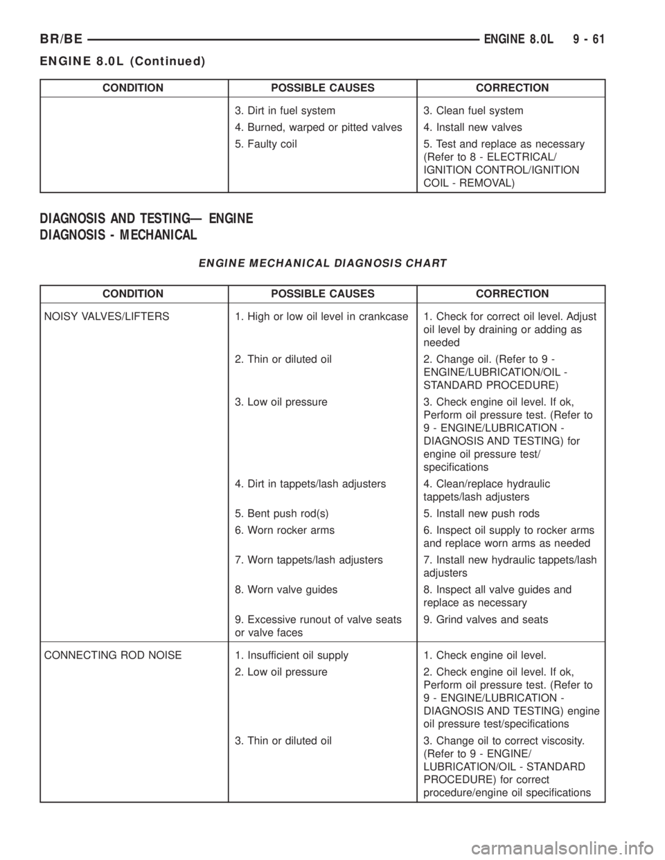
CONDITION POSSIBLE CAUSES CORRECTION
3. Dirt in fuel system 3. Clean fuel system
4. Burned, warped or pitted valves 4. Install new valves
5. Faulty coil 5. Test and replace as necessary
(Refer to 8 - ELECTRICAL/
IGNITION CONTROL/IGNITION
COIL - REMOVAL)
DIAGNOSIS AND TESTINGÐ ENGINE
DIAGNOSIS - MECHANICAL
ENGINE MECHANICAL DIAGNOSIS CHART
CONDITION POSSIBLE CAUSES CORRECTION
NOISY VALVES/LIFTERS 1. High or low oil level in crankcase 1. Check for correct oil level. Adjust
oil level by draining or adding as
needed
2. Thin or diluted oil 2. Change oil. (Refer to 9 -
ENGINE/LUBRICATION/OIL -
STANDARD PROCEDURE)
3. Low oil pressure 3. Check engine oil level. If ok,
Perform oil pressure test. (Refer to
9 - ENGINE/LUBRICATION -
DIAGNOSIS AND TESTING) for
engine oil pressure test/
specifications
4. Dirt in tappets/lash adjusters 4. Clean/replace hydraulic
tappets/lash adjusters
5. Bent push rod(s) 5. Install new push rods
6. Worn rocker arms 6. Inspect oil supply to rocker arms
and replace worn arms as needed
7. Worn tappets/lash adjusters 7. Install new hydraulic tappets/lash
adjusters
8. Worn valve guides 8. Inspect all valve guides and
replace as necessary
9. Excessive runout of valve seats
or valve faces9. Grind valves and seats
CONNECTING ROD NOISE 1. Insufficient oil supply 1. Check engine oil level.
2. Low oil pressure 2. Check engine oil level. If ok,
Perform oil pressure test. (Refer to
9 - ENGINE/LUBRICATION -
DIAGNOSIS AND TESTING) engine
oil pressure test/specifications
3. Thin or diluted oil 3. Change oil to correct viscosity.
(Refer to 9 - ENGINE/
LUBRICATION/OIL - STANDARD
PROCEDURE) for correct
procedure/engine oil specifications
BR/BEENGINE 8.0L 9 - 61
ENGINE 8.0L (Continued)
Page 1137 of 2255
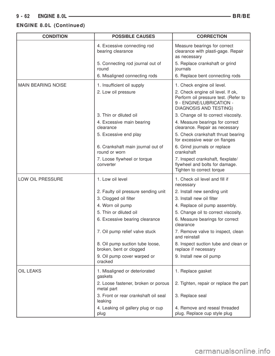
CONDITION POSSIBLE CAUSES CORRECTION
4. Excessive connecting rod
bearing clearanceMeasure bearings for correct
clearance with plasti-gage. Repair
as necessary
5. Connecting rod journal out of
round5. Replace crankshaft or grind
journals
6. Misaligned connecting rods 6. Replace bent connecting rods
MAIN BEARING NOISE 1. Insufficient oil supply 1. Check engine oil level.
2. Low oil pressure 2. Check engine oil level. If ok,
Perform oil pressure test. (Refer to
9 - ENGINE/LUBRICATION -
DIAGNOSIS AND TESTING)
3. Thin or diluted oil 3. Change oil to correct viscosity.
4. Excessive main bearing
clearance4. Measure bearings for correct
clearance. Repair as necessary
5. Excessive end play 5. Check crankshaft thrust bearing
for excessive wear on flanges
6. Crankshaft main journal out of
round or worn6. Grind journals or replace
crankshaft
7. Loose flywheel or torque
converter7. Inspect crankshaft, flexplate/
flywheel and bolts for damage.
Tighten to correct torque
LOW OIL PRESSURE 1. Low oil level 1. Check oil level and fill if
necessary
2. Faulty oil pressure sending unit 2. Install new sending unit
3. Clogged oil filter 3. Install new oil filter
4. Worn oil pump 4. Replace oil pump assembly.
5. Thin or diluted oil 5. Change oil to correct viscosity.
6. Excessive bearing clearance 6. Measure bearings for correct
clearance
7. Oil pump relief valve stuck 7. Remove valve to inspect, clean
and reinstall
8. Oil pump suction tube loose,
broken, bent or clogged8. Inspect suction tube and clean or
replace if necessary
9. Oil pump cover warped or
cracked9. Install new oil pump
OIL LEAKS 1. Misaligned or deteriorated
gaskets1. Replace gasket
2. Loose fastener, broken or porous
metal part2. Tighten, repair or replace the part
3. Front or rear crankshaft oil seal
leaking3. Replace seal
4. Leaking oil gallery plug or cup
plug4. Remove and reseal threaded
plug. Replace cup style plug
9 - 62 ENGINE 8.0LBR/BE
ENGINE 8.0L (Continued)
Page 1191 of 2255
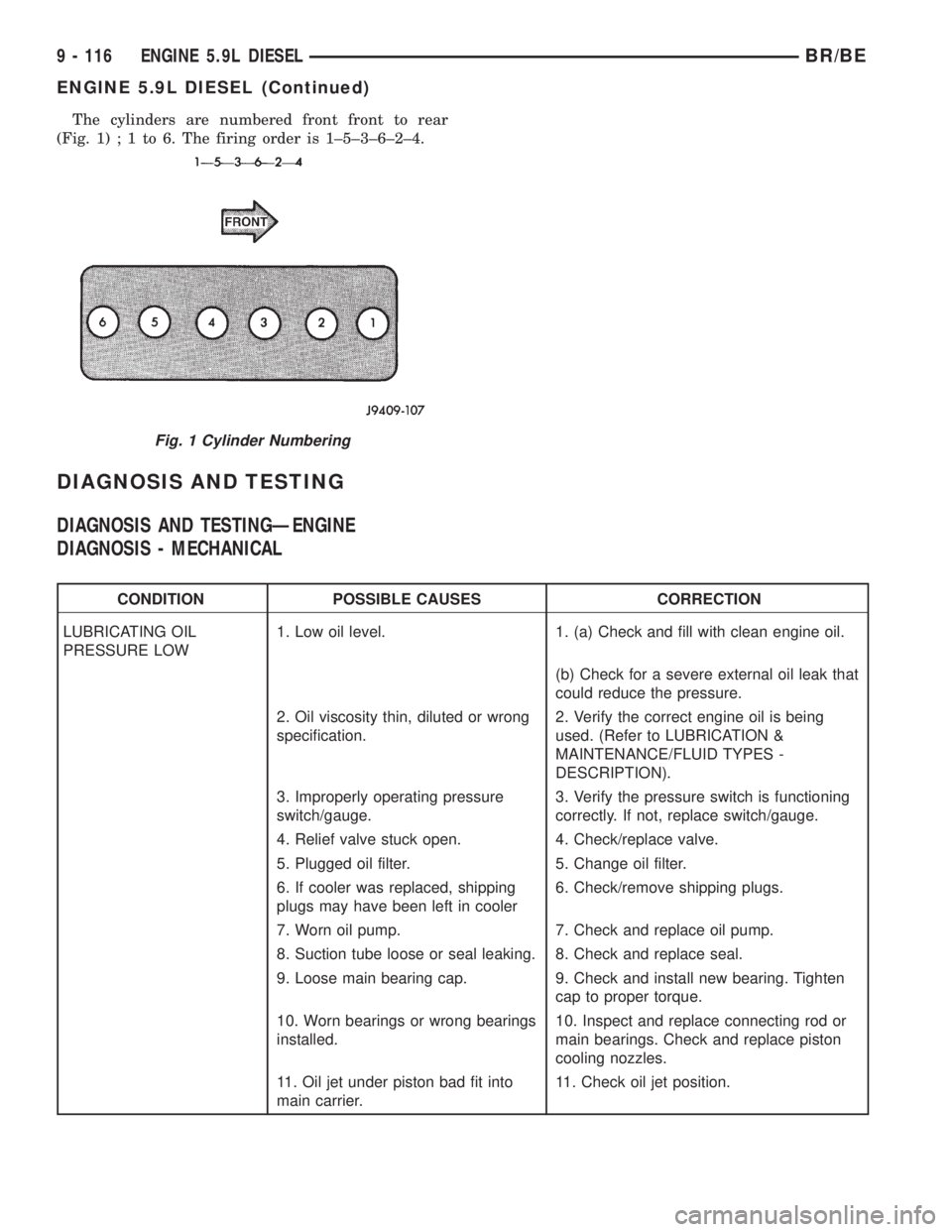
The cylinders are numbered front front to rear
(Fig. 1);1to6.Thefiring order is 1±5±3±6±2±4.
DIAGNOSIS AND TESTING
DIAGNOSIS AND TESTINGÐENGINE
DIAGNOSIS - MECHANICAL
CONDITION POSSIBLE CAUSES CORRECTION
LUBRICATING OIL
PRESSURE LOW1. Low oil level. 1. (a) Check and fill with clean engine oil.
(b) Check for a severe external oil leak that
could reduce the pressure.
2. Oil viscosity thin, diluted or wrong
specification.2. Verify the correct engine oil is being
used. (Refer to LUBRICATION &
MAINTENANCE/FLUID TYPES -
DESCRIPTION).
3. Improperly operating pressure
switch/gauge.3. Verify the pressure switch is functioning
correctly. If not, replace switch/gauge.
4. Relief valve stuck open. 4. Check/replace valve.
5. Plugged oil filter. 5. Change oil filter.
6. If cooler was replaced, shipping
plugs may have been left in cooler6. Check/remove shipping plugs.
7. Worn oil pump. 7. Check and replace oil pump.
8. Suction tube loose or seal leaking. 8. Check and replace seal.
9. Loose main bearing cap. 9. Check and install new bearing. Tighten
cap to proper torque.
10. Worn bearings or wrong bearings
installed.10. Inspect and replace connecting rod or
main bearings. Check and replace piston
cooling nozzles.
11. Oil jet under piston bad fit into
main carrier.11. Check oil jet position.
Fig. 1 Cylinder Numbering
9 - 116 ENGINE 5.9L DIESELBR/BE
ENGINE 5.9L DIESEL (Continued)