2002 CHRYSLER VOYAGER rear light
[x] Cancel search: rear lightPage 1440 of 2399
FRAME & BUMPERS
TABLE OF CONTENTS
page page
BUMPERS
SPECIFICATIONS - TORQUE...............1
FRONT FASCIA
REMOVAL.............................1
INSTALLATION..........................1
FRONT BUMPER REINFORCEMENT
REMOVAL.............................2
INSTALLATION..........................2
REAR FASCIA
REMOVAL.............................3
INSTALLATION..........................3
REAR BUMPER REINFORCEMENT
REMOVAL.............................3
INSTALLATION..........................3
REAR FASCIA - SCUFF PAD
REMOVAL.............................4INSTALLATION..........................4
FRAME
SPECIFICATIONS
FRAME DIMENSIONS...................4
SPECIFICATIONS - TORQUE.............9
FRONT CRADLE CROSSMEMBER
DESCRIPTION
DESCRIPTION - FRONT CRADLE
CROSSMEMBER.......................9
DESCRIPTION - FRONT CRADLE
CROSSMEMBER THREAD REPAIR.........9
REMOVAL.............................10
INSTALLATION.........................12
FRONT CROSSMEMBER MOUNT BUSHINGS
REMOVAL.............................12
INSTALLATION.........................12
BUMPERS
SPECIFICATIONS - TORQUE
DESCRIPTION N´m Ft. Lbs. In. Lbs.
Front bumper reinforcement attaching nut 54 40 Ð
Rear bumper reinforcement attaching nut 27 20 Ð
FRONT FASCIA
REMOVAL
(1) Release hood latch and open hood.
(2) Remove the headlamp assemblies (Refer to 8 -
ELECTRICAL/LAMPS/LIGHTING - EXTERIOR/
HEADLAMP - REMOVAL).
(3) Hoist vehicle and support with safety stands.
(4) Remove the five bolts attaching bottom of fas-
cia/air dam to radiator closure panel.
(5) Remove front wheels.
(6) Remove front wheelhouse splash shields fasten-
ers as necessary to gain access to bolts attaching
front fascia to fender. (Refer to 23 - BODY/EXTERI-
OR/ WHEELHOUSE SPLASH SHIELD - REMOV-
AL).
(7) Remove the two bolts and two nuts attaching
fascia to the front fenders (Fig. 1).
(8) Disconnect fog lamp wire connectors, if neces-
sary.
(9) Lower vehicle.(10) Remove two bolts attaching the upper grille
support to the headlamp mounting panel at each side
of the grille.
(11) Remove bumper fascia from vehicle.
INSTALLATION
(1) Position front bumper fascia on vehicle.
(2) Install the two bolts attaching fascia to head-
lamp mounting panel at each side of grille.
(3) Hoist vehicle and support with safety stands.
(4) Install the two bolts and two nuts attaching
fascia to the front fenders (Fig. 1). The fascia should
be flush to fender.
(5) Install front wheelhouse splash shields fasten-
ers. (Refer to 23 - BODY/EXTERIOR/ WHEEL-
HOUSE SPLASH SHIELD - INSTALLATION).
(6) Install front wheels.
(7) Connect fog lamp wire connectors, if necessary.
(8) Install the five bolts attaching bottom of fascia
to radiator closure panel.
(9) Lower the vehicle.
RSFRAME & BUMPERS13-1
ProCarManuals.com
Page 1541 of 2399
(2) Fill the fluid reservoir to the proper level and
let the fluid settle for at least two (2) minutes.
(3) Start the engine and let run for a few seconds,
then turn the engine off.
(4) Add fluid if necessary. Repeat the above steps
until the fluid level remains constant after running
the engine.
(5) Raise the front wheels off the ground.
(6) Start the engine.
(7) Slowly turn the steering wheel right and left,
lightly contacting the wheel stops.
(8) Add fluid if necessary.
(9) Lower the vehicle, then turn the steering wheel
slowly from lock-to-lock.
(10) Stop the engine. Check the fluid level and
refill as required.
(11) If the fluid is extremely foamy, allow the vehi-
cle to stabilize a few minutes, then repeat the above
procedure.
REMOVAL
REMOVAL - PUMP (2.4L ENGINE)
(1) Remove the (-) negative battery cable from the
battery and isolate cable.
(2) Remove the cap from the power steering fluid
reservoir.
(3) Using a siphon pump, remove as much power
steering fluid as possible from the power steering
fluid reservoir.
(4) Raise the vehicle on jack stands or centered on
a frame contact type hoist. See Hoisting in Lubrica-
tion and Maintenance.
(5) Disconnect the oxygen sensor wiring harness
from the vehicle wiring harness at the rear engine
mount bracket.
NOTE: The exhaust system needs to be removed
from the engine to allow for an area to remove the
power steering pump from the vehicle.
(6) Remove the four bolts and flag nuts securing
the catalytic converter from the exhaust manifold
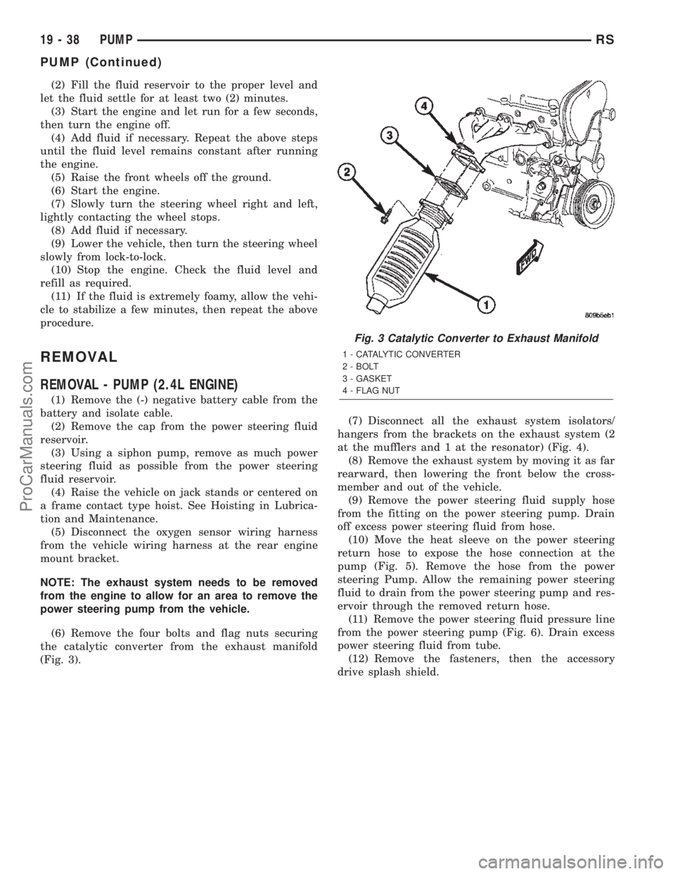
(Fig. 3).(7) Disconnect all the exhaust system isolators/
hangers from the brackets on the exhaust system (2
at the mufflers and 1 at the resonator) (Fig. 4).
(8) Remove the exhaust system by moving it as far
rearward, then lowering the front below the cross-
member and out of the vehicle.
(9) Remove the power steering fluid supply hose
from the fitting on the power steering pump. Drain
off excess power steering fluid from hose.
(10) Move the heat sleeve on the power steering
return hose to expose the hose connection at the
pump (Fig. 5). Remove the hose from the power
steering Pump. Allow the remaining power steering
fluid to drain from the power steering pump and res-
ervoir through the removed return hose.
(11) Remove the power steering fluid pressure line
from the power steering pump (Fig. 6). Drain excess
power steering fluid from tube.
(12) Remove the fasteners, then the accessory
drive splash shield.
Fig. 3 Catalytic Converter to Exhaust Manifold
1 - CATALYTIC CONVERTER
2 - BOLT
3 - GASKET
4 - FLAG NUT
19 - 38 PUMPRS
PUMP (Continued)
ProCarManuals.com
Page 1561 of 2399
FLUID LEAK DIAGNOSIS
When diagnosing fluid leaks on the Power Transfer
Unit two weep holes are provided to diagnose certain
seal leaks. These holes are located on the bottom side
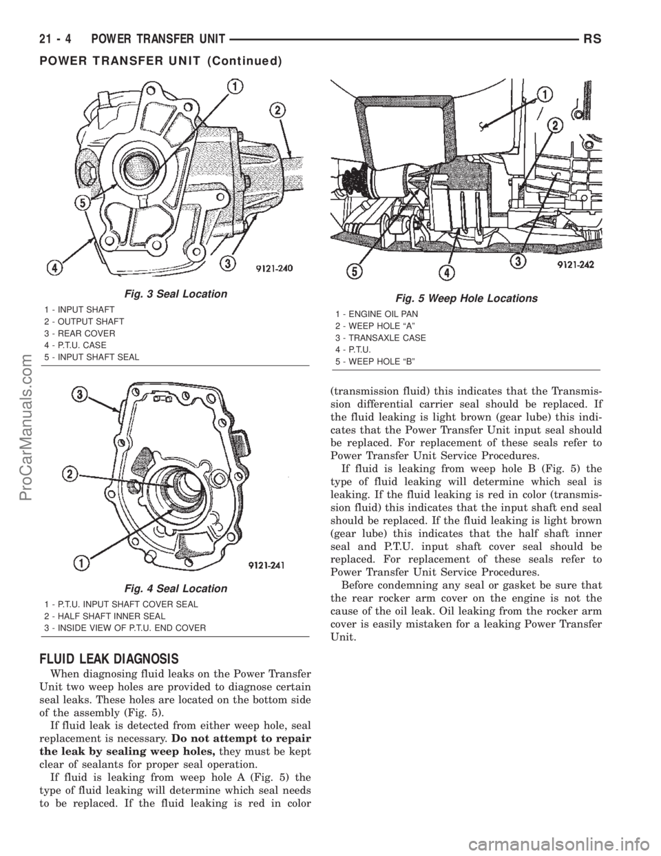
of the assembly (Fig. 5).
If fluid leak is detected from either weep hole, seal
replacement is necessary.Do not attempt to repair
the leak by sealing weep holes,they must be kept
clear of sealants for proper seal operation.
If fluid is leaking from weep hole A (Fig. 5) the
type of fluid leaking will determine which seal needs
to be replaced. If the fluid leaking is red in color(transmission fluid) this indicates that the Transmis-
sion differential carrier seal should be replaced. If
the fluid leaking is light brown (gear lube) this indi-
cates that the Power Transfer Unit input seal should
be replaced. For replacement of these seals refer to
Power Transfer Unit Service Procedures.
If fluid is leaking from weep hole B (Fig. 5) the
type of fluid leaking will determine which seal is
leaking. If the fluid leaking is red in color (transmis-
sion fluid) this indicates that the input shaft end seal
should be replaced. If the fluid leaking is light brown
(gear lube) this indicates that the half shaft inner
seal and P.T.U. input shaft cover seal should be
replaced. For replacement of these seals refer to
Power Transfer Unit Service Procedures.
Before condemning any seal or gasket be sure that
the rear rocker arm cover on the engine is not the
cause of the oil leak. Oil leaking from the rocker arm
cover is easily mistaken for a leaking Power Transfer
Unit.
Fig. 3 Seal Location
1 - INPUT SHAFT
2 - OUTPUT SHAFT
3 - REAR COVER
4 - P.T.U. CASE
5 - INPUT SHAFT SEAL
Fig. 4 Seal Location
1 - P.T.U. INPUT SHAFT COVER SEAL
2 - HALF SHAFT INNER SEAL
3 - INSIDE VIEW OF P.T.U. END COVER
Fig. 5 Weep Hole Locations
1 - ENGINE OIL PAN
2 - WEEP HOLE ªAº
3 - TRANSAXLE CASE
4 - P.T.U.
5 - WEEP HOLE ªBº
21 - 4 POWER TRANSFER UNITRS
POWER TRANSFER UNIT (Continued)
ProCarManuals.com
Page 1683 of 2399
OPERATION
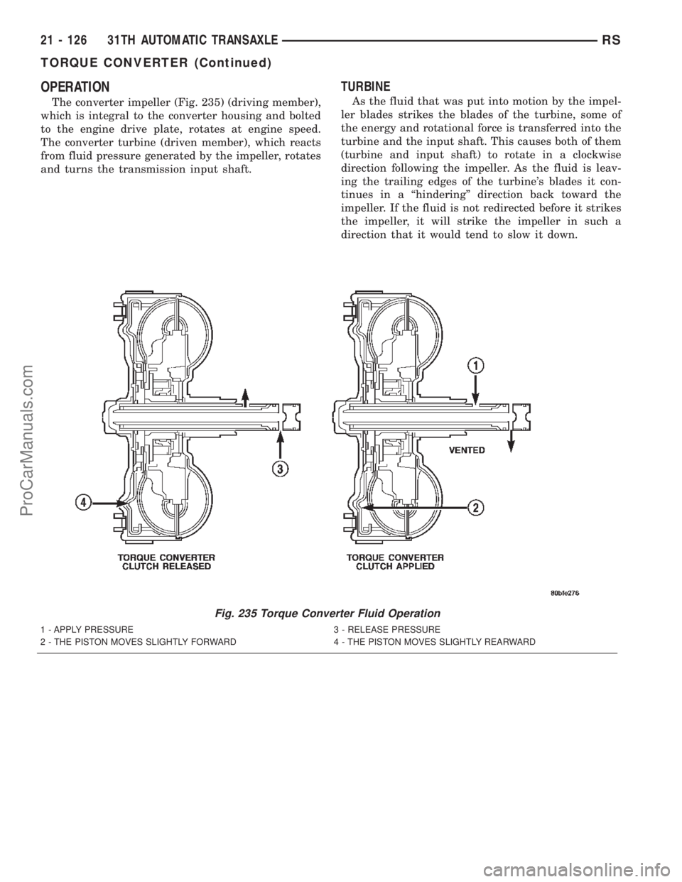
The converter impeller (Fig. 235) (driving member),
which is integral to the converter housing and bolted
to the engine drive plate, rotates at engine speed.
The converter turbine (driven member), which reacts
from fluid pressure generated by the impeller, rotates
and turns the transmission input shaft.
TURBINE
As the fluid that was put into motion by the impel-
ler blades strikes the blades of the turbine, some of
the energy and rotational force is transferred into the
turbine and the input shaft. This causes both of them
(turbine and input shaft) to rotate in a clockwise
direction following the impeller. As the fluid is leav-
ing the trailing edges of the turbine's blades it con-
tinues in a ªhinderingº direction back toward the
impeller. If the fluid is not redirected before it strikes
the impeller, it will strike the impeller in such a
direction that it would tend to slow it down.
Fig. 235 Torque Converter Fluid Operation
1 - APPLY PRESSURE 3 - RELEASE PRESSURE
2 - THE PISTON MOVES SLIGHTLY FORWARD 4 - THE PISTON MOVES SLIGHTLY REARWARD
21 - 126 31TH AUTOMATIC TRANSAXLERS
TORQUE CONVERTER (Continued)
ProCarManuals.com
Page 1684 of 2399
STATOR
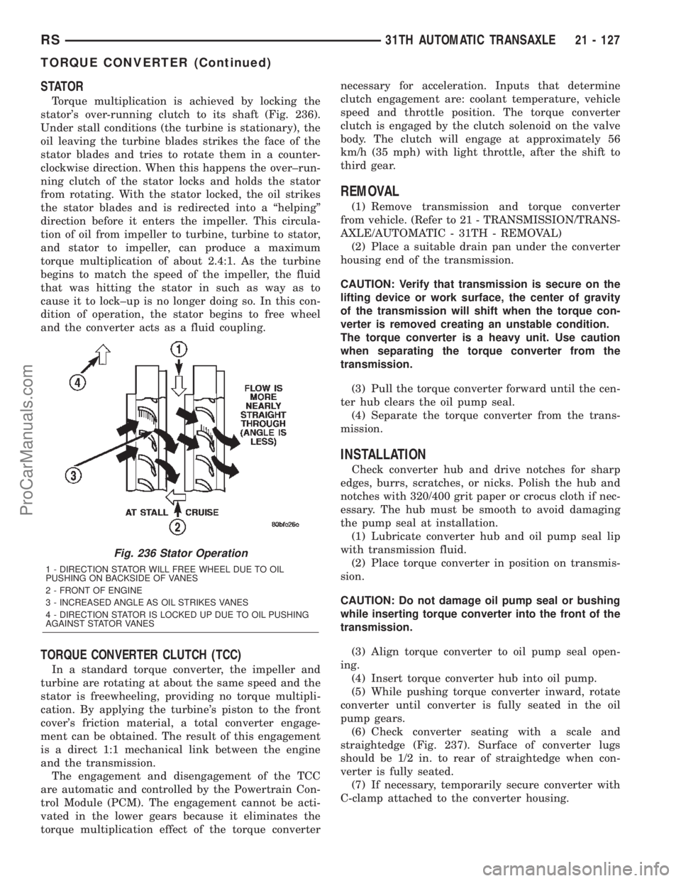
Torque multiplication is achieved by locking the
stator's over-running clutch to its shaft (Fig. 236).
Under stall conditions (the turbine is stationary), the
oil leaving the turbine blades strikes the face of the
stator blades and tries to rotate them in a counter-
clockwise direction. When this happens the over±run-
ning clutch of the stator locks and holds the stator
from rotating. With the stator locked, the oil strikes
the stator blades and is redirected into a ªhelpingº
direction before it enters the impeller. This circula-
tion of oil from impeller to turbine, turbine to stator,
and stator to impeller, can produce a maximum
torque multiplication of about 2.4:1. As the turbine
begins to match the speed of the impeller, the fluid
that was hitting the stator in such as way as to
cause it to lock±up is no longer doing so. In this con-
dition of operation, the stator begins to free wheel
and the converter acts as a fluid coupling.
TORQUE CONVERTER CLUTCH (TCC)
In a standard torque converter, the impeller and
turbine are rotating at about the same speed and the
stator is freewheeling, providing no torque multipli-
cation. By applying the turbine's piston to the front
cover's friction material, a total converter engage-
ment can be obtained. The result of this engagement
is a direct 1:1 mechanical link between the engine
and the transmission.
The engagement and disengagement of the TCC
are automatic and controlled by the Powertrain Con-
trol Module (PCM). The engagement cannot be acti-
vated in the lower gears because it eliminates the
torque multiplication effect of the torque converternecessary for acceleration. Inputs that determine
clutch engagement are: coolant temperature, vehicle
speed and throttle position. The torque converter
clutch is engaged by the clutch solenoid on the valve
body. The clutch will engage at approximately 56
km/h (35 mph) with light throttle, after the shift to
third gear.
REMOVAL
(1) Remove transmission and torque converter
from vehicle. (Refer to 21 - TRANSMISSION/TRANS-
AXLE/AUTOMATIC - 31TH - REMOVAL)
(2) Place a suitable drain pan under the converter
housing end of the transmission.
CAUTION: Verify that transmission is secure on the
lifting device or work surface, the center of gravity
of the transmission will shift when the torque con-
verter is removed creating an unstable condition.
The torque converter is a heavy unit. Use caution
when separating the torque converter from the
transmission.
(3) Pull the torque converter forward until the cen-
ter hub clears the oil pump seal.
(4) Separate the torque converter from the trans-
mission.
INSTALLATION
Check converter hub and drive notches for sharp
edges, burrs, scratches, or nicks. Polish the hub and
notches with 320/400 grit paper or crocus cloth if nec-
essary. The hub must be smooth to avoid damaging
the pump seal at installation.
(1) Lubricate converter hub and oil pump seal lip
with transmission fluid.
(2) Place torque converter in position on transmis-
sion.
CAUTION: Do not damage oil pump seal or bushing
while inserting torque converter into the front of the
transmission.
(3) Align torque converter to oil pump seal open-
ing.
(4) Insert torque converter hub into oil pump.
(5) While pushing torque converter inward, rotate
converter until converter is fully seated in the oil
pump gears.
(6) Check converter seating with a scale and
straightedge (Fig. 237). Surface of converter lugs
should be 1/2 in. to rear of straightedge when con-
verter is fully seated.
(7) If necessary, temporarily secure converter with
C-clamp attached to the converter housing.
Fig. 236 Stator Operation
1 - DIRECTION STATOR WILL FREE WHEEL DUE TO OIL
PUSHING ON BACKSIDE OF VANES
2 - FRONT OF ENGINE
3 - INCREASED ANGLE AS OIL STRIKES VANES
4 - DIRECTION STATOR IS LOCKED UP DUE TO OIL PUSHING
AGAINST STATOR VANES
RS31TH AUTOMATIC TRANSAXLE21 - 127
TORQUE CONVERTER (Continued)
ProCarManuals.com
Page 1846 of 2399
OPERATION
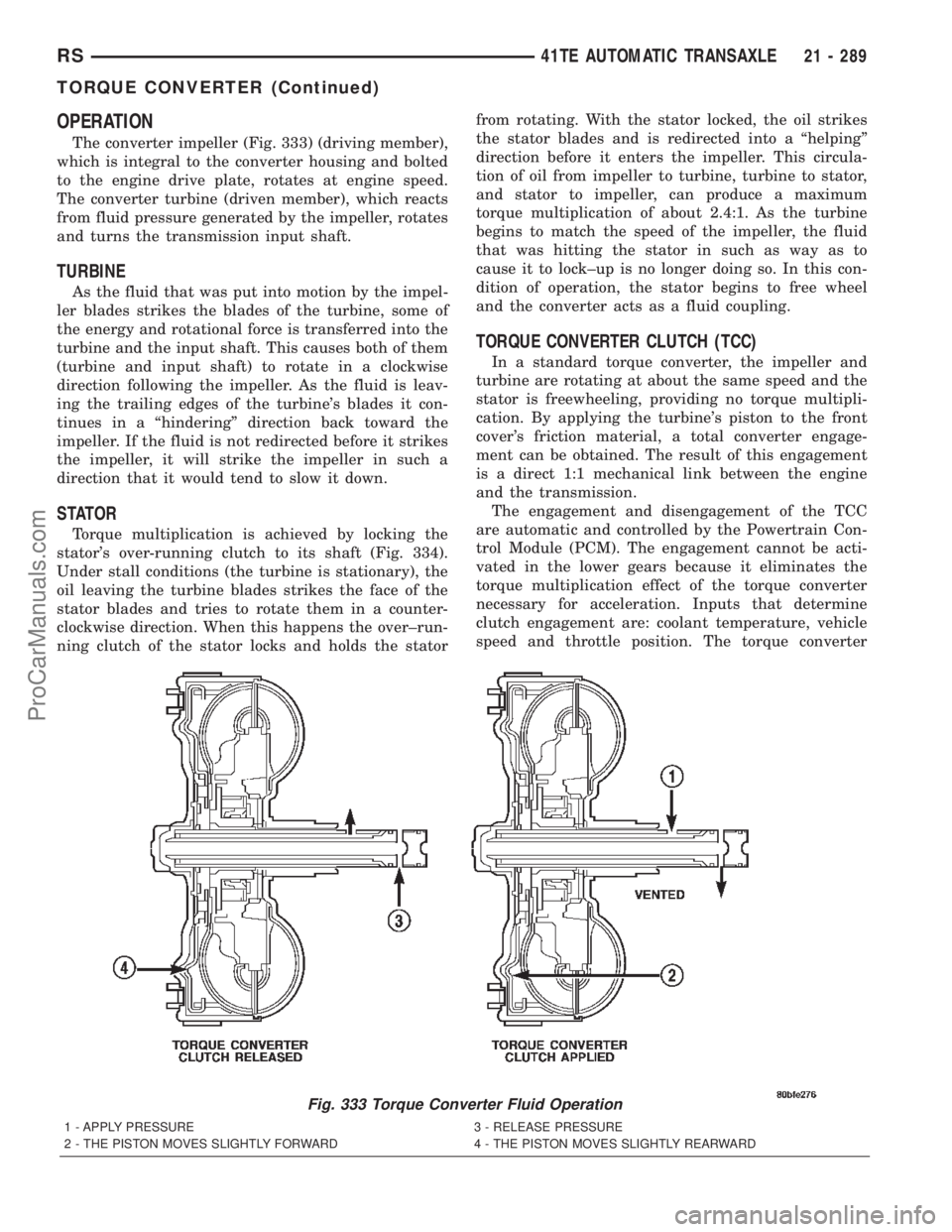
The converter impeller (Fig. 333) (driving member),
which is integral to the converter housing and bolted
to the engine drive plate, rotates at engine speed.
The converter turbine (driven member), which reacts
from fluid pressure generated by the impeller, rotates
and turns the transmission input shaft.
TURBINE
As the fluid that was put into motion by the impel-
ler blades strikes the blades of the turbine, some of
the energy and rotational force is transferred into the
turbine and the input shaft. This causes both of them
(turbine and input shaft) to rotate in a clockwise
direction following the impeller. As the fluid is leav-
ing the trailing edges of the turbine's blades it con-
tinues in a ªhinderingº direction back toward the
impeller. If the fluid is not redirected before it strikes
the impeller, it will strike the impeller in such a
direction that it would tend to slow it down.
STATOR
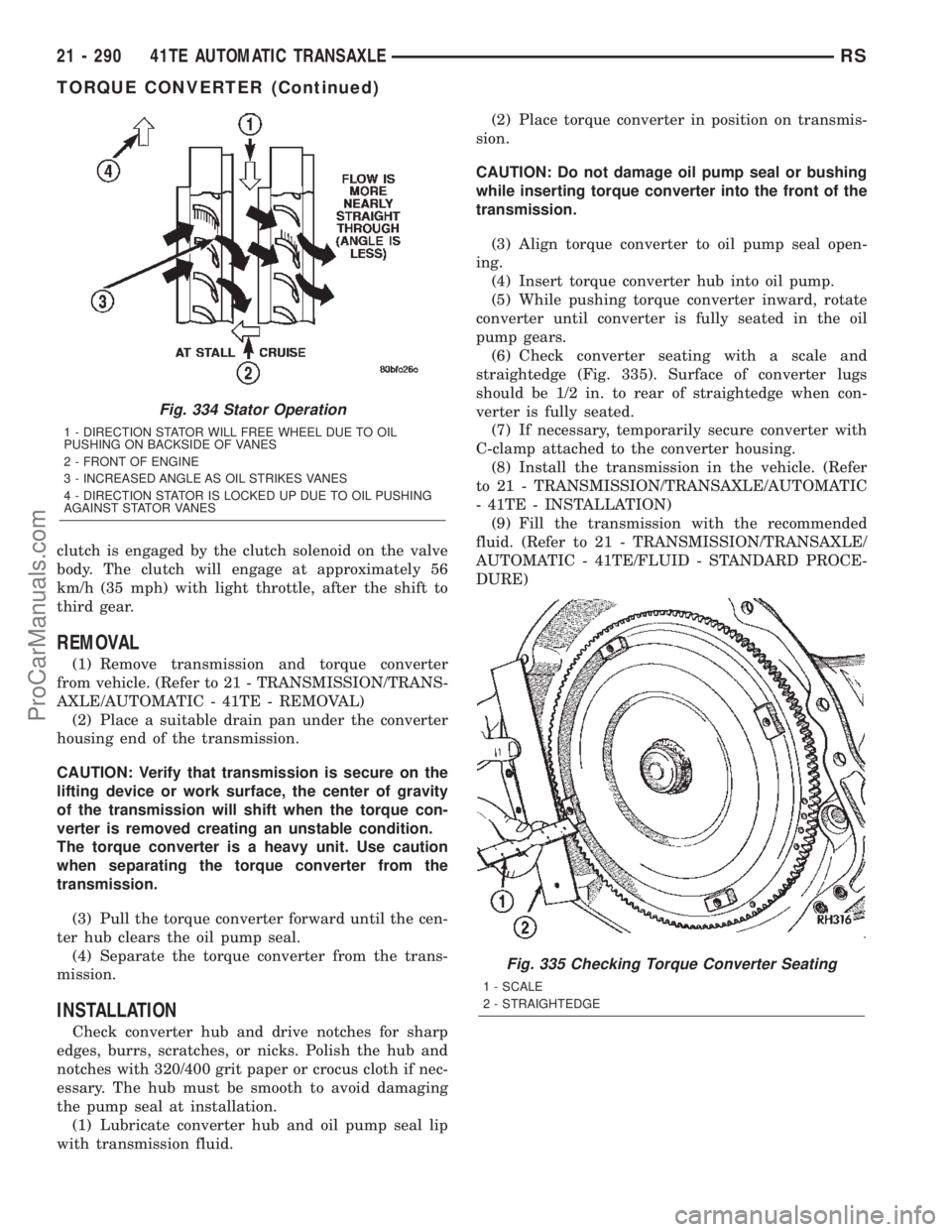
Torque multiplication is achieved by locking the
stator's over-running clutch to its shaft (Fig. 334).
Under stall conditions (the turbine is stationary), the
oil leaving the turbine blades strikes the face of the
stator blades and tries to rotate them in a counter-
clockwise direction. When this happens the over±run-
ning clutch of the stator locks and holds the statorfrom rotating. With the stator locked, the oil strikes
the stator blades and is redirected into a ªhelpingº
direction before it enters the impeller. This circula-
tion of oil from impeller to turbine, turbine to stator,
and stator to impeller, can produce a maximum
torque multiplication of about 2.4:1. As the turbine
begins to match the speed of the impeller, the fluid
that was hitting the stator in such as way as to
cause it to lock±up is no longer doing so. In this con-
dition of operation, the stator begins to free wheel
and the converter acts as a fluid coupling.
TORQUE CONVERTER CLUTCH (TCC)
In a standard torque converter, the impeller and
turbine are rotating at about the same speed and the
stator is freewheeling, providing no torque multipli-
cation. By applying the turbine's piston to the front
cover's friction material, a total converter engage-
ment can be obtained. The result of this engagement
is a direct 1:1 mechanical link between the engine
and the transmission.
The engagement and disengagement of the TCC
are automatic and controlled by the Powertrain Con-
trol Module (PCM). The engagement cannot be acti-
vated in the lower gears because it eliminates the
torque multiplication effect of the torque converter
necessary for acceleration. Inputs that determine
clutch engagement are: coolant temperature, vehicle
speed and throttle position. The torque converter
Fig. 333 Torque Converter Fluid Operation
1 - APPLY PRESSURE 3 - RELEASE PRESSURE
2 - THE PISTON MOVES SLIGHTLY FORWARD 4 - THE PISTON MOVES SLIGHTLY REARWARD
RS41TE AUTOMATIC TRANSAXLE21 - 289
TORQUE CONVERTER (Continued)
ProCarManuals.com
Page 1847 of 2399
clutch is engaged by the clutch solenoid on the valve
body. The clutch will engage at approximately 56
km/h (35 mph) with light throttle, after the shift to
third gear.
REMOVAL
(1) Remove transmission and torque converter
from vehicle. (Refer to 21 - TRANSMISSION/TRANS-
AXLE/AUTOMATIC - 41TE - REMOVAL)
(2) Place a suitable drain pan under the converter
housing end of the transmission.
CAUTION: Verify that transmission is secure on the
lifting device or work surface, the center of gravity
of the transmission will shift when the torque con-
verter is removed creating an unstable condition.
The torque converter is a heavy unit. Use caution
when separating the torque converter from the
transmission.
(3) Pull the torque converter forward until the cen-
ter hub clears the oil pump seal.
(4) Separate the torque converter from the trans-
mission.
INSTALLATION
Check converter hub and drive notches for sharp
edges, burrs, scratches, or nicks. Polish the hub and
notches with 320/400 grit paper or crocus cloth if nec-
essary. The hub must be smooth to avoid damaging
the pump seal at installation.
(1) Lubricate converter hub and oil pump seal lip
with transmission fluid.(2) Place torque converter in position on transmis-
sion.
CAUTION: Do not damage oil pump seal or bushing
while inserting torque converter into the front of the
transmission.
(3) Align torque converter to oil pump seal open-
ing.
(4) Insert torque converter hub into oil pump.
(5) While pushing torque converter inward, rotate
converter until converter is fully seated in the oil
pump gears.
(6) Check converter seating with a scale and
straightedge (Fig. 335). Surface of converter lugs
should be 1/2 in. to rear of straightedge when con-
verter is fully seated.
(7) If necessary, temporarily secure converter with
C-clamp attached to the converter housing.
(8) Install the transmission in the vehicle. (Refer
to 21 - TRANSMISSION/TRANSAXLE/AUTOMATIC
- 41TE - INSTALLATION)
(9) Fill the transmission with the recommended
fluid. (Refer to 21 - TRANSMISSION/TRANSAXLE/
AUTOMATIC - 41TE/FLUID - STANDARD PROCE-
DURE)
Fig. 334 Stator Operation
1 - DIRECTION STATOR WILL FREE WHEEL DUE TO OIL
PUSHING ON BACKSIDE OF VANES
2 - FRONT OF ENGINE
3 - INCREASED ANGLE AS OIL STRIKES VANES
4 - DIRECTION STATOR IS LOCKED UP DUE TO OIL PUSHING
AGAINST STATOR VANES
Fig. 335 Checking Torque Converter Seating
1 - SCALE
2 - STRAIGHTEDGE
21 - 290 41TE AUTOMATIC TRANSAXLERS
TORQUE CONVERTER (Continued)
ProCarManuals.com
Page 1963 of 2399
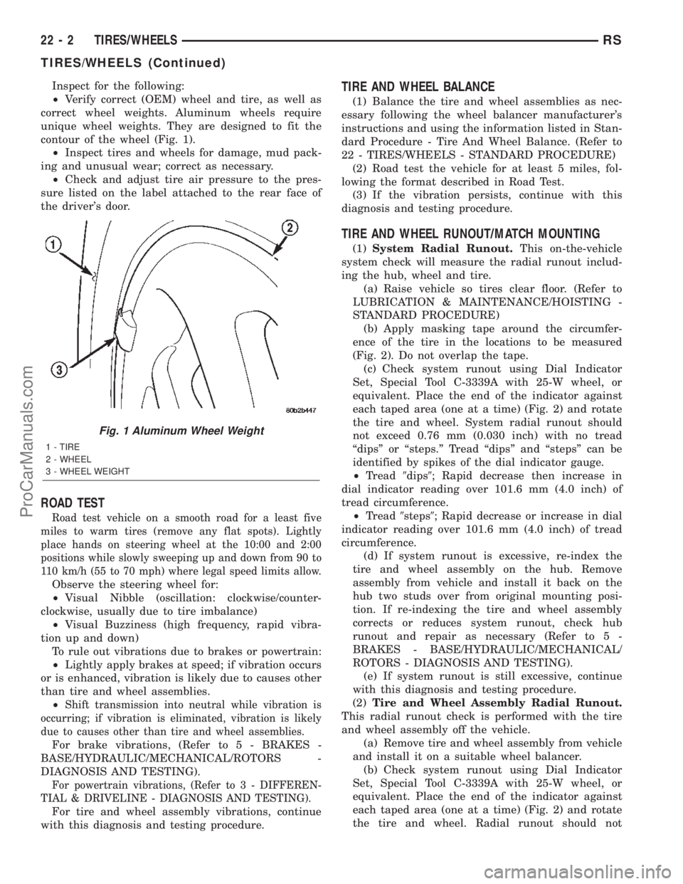
Inspect for the following:
²Verify correct (OEM) wheel and tire, as well as
correct wheel weights. Aluminum wheels require
unique wheel weights. They are designed to fit the
contour of the wheel (Fig. 1).
²Inspect tires and wheels for damage, mud pack-
ing and unusual wear; correct as necessary.
²Check and adjust tire air pressure to the pres-
sure listed on the label attached to the rear face of
the driver's door.
ROAD TEST
Road test vehicle on a smooth road for a least five
miles to warm tires (remove any flat spots). Lightly
place hands on steering wheel at the 10:00 and 2:00
positions while slowly sweeping up and down from 90 to
110 km/h (55 to 70 mph) where legal speed limits allow.
Observe the steering wheel for:
²Visual Nibble (oscillation: clockwise/counter-
clockwise, usually due to tire imbalance)
²Visual Buzziness (high frequency, rapid vibra-
tion up and down)
To rule out vibrations due to brakes or powertrain:
²Lightly apply brakes at speed; if vibration occurs
or is enhanced, vibration is likely due to causes other
than tire and wheel assemblies.
²
Shift transmission into neutral while vibration is
occurring; if vibration is eliminated, vibration is likely
due to causes other than tire and wheel assemblies.
For brake vibrations, (Refer to 5 - BRAKES -
BASE/HYDRAULIC/MECHANICAL/ROTORS -
DIAGNOSIS AND TESTING).
For powertrain vibrations, (Refer to 3 - DIFFEREN-
TIAL & DRIVELINE - DIAGNOSIS AND TESTING).
For tire and wheel assembly vibrations, continue
with this diagnosis and testing procedure.
TIRE AND WHEEL BALANCE
(1) Balance the tire and wheel assemblies as nec-
essary following the wheel balancer manufacturer's
instructions and using the information listed in Stan-
dard Procedure - Tire And Wheel Balance. (Refer to
22 - TIRES/WHEELS - STANDARD PROCEDURE)
(2) Road test the vehicle for at least 5 miles, fol-
lowing the format described in Road Test.
(3) If the vibration persists, continue with this
diagnosis and testing procedure.
TIRE AND WHEEL RUNOUT/MATCH MOUNTING
(1)System Radial Runout.This on-the-vehicle
system check will measure the radial runout includ-
ing the hub, wheel and tire.
(a) Raise vehicle so tires clear floor. (Refer to
LUBRICATION & MAINTENANCE/HOISTING -
STANDARD PROCEDURE)
(b) Apply masking tape around the circumfer-
ence of the tire in the locations to be measured
(Fig. 2). Do not overlap the tape.
(c) Check system runout using Dial Indicator
Set, Special Tool C-3339A with 25-W wheel, or
equivalent. Place the end of the indicator against
each taped area (one at a time) (Fig. 2) and rotate
the tire and wheel. System radial runout should
not exceed 0.76 mm (0.030 inch) with no tread
ªdipsº or ªsteps.º Tread ªdipsº and ªstepsº can be
identified by spikes of the dial indicator gauge.
²Tread9dips9; Rapid decrease then increase in
dial indicator reading over 101.6 mm (4.0 inch) of
tread circumference.
²Tread9steps9; Rapid decrease or increase in dial
indicator reading over 101.6 mm (4.0 inch) of tread
circumference.
(d) If system runout is excessive, re-index the
tire and wheel assembly on the hub. Remove
assembly from vehicle and install it back on the
hub two studs over from original mounting posi-
tion. If re-indexing the tire and wheel assembly
corrects or reduces system runout, check hub
runout and repair as necessary (Refer to 5 -
BRAKES - BASE/HYDRAULIC/MECHANICAL/
ROTORS - DIAGNOSIS AND TESTING).
(e) If system runout is still excessive, continue
with this diagnosis and testing procedure.
(2)Tire and Wheel Assembly Radial Runout.
This radial runout check is performed with the tire
and wheel assembly off the vehicle.
(a) Remove tire and wheel assembly from vehicle
and install it on a suitable wheel balancer.
(b) Check system runout using Dial Indicator
Set, Special Tool C-3339A with 25-W wheel, or
equivalent. Place the end of the indicator against
each taped area (one at a time) (Fig. 2) and rotate
the tire and wheel. Radial runout should not
Fig. 1 Aluminum Wheel Weight
1 - TIRE
2 - WHEEL
3 - WHEEL WEIGHT
22 - 2 TIRES/WHEELSRS
TIRES/WHEELS (Continued)
ProCarManuals.com