2002 CHRYSLER VOYAGER Brake line
[x] Cancel search: Brake linePage 1661 of 2399
ADJUSTMENTS
GEARSHIFT CABLE ADJUSTMENT
Lift and rotate the gearshift hand lever into the
park (P) gate position and remove the ignition key.
This confirms the shift lever is in the gated park (P)
position.
After confirming the park gate position, turn the
ignition switch . If the starter will operate, the park
gate position is correct. Move the shift lever into the
neutral (N) position. If the starter will operate in this
position, the linkage is properly adjusted. If the
starter fails to operate in either position, linkage
adjustment is required.
(1) Park the vehicle on level ground and set the
parking brake.
(2) Place the gearshift lever in park (P) gate posi-
tion and remove key.
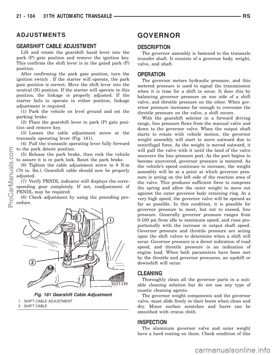
(3) Loosen the cable adjustment screw at the
transaxle operating lever (Fig. 181).
(4) Pull the transaxle operating lever fully forward
to the park detent position.
(5) Release the park brake, then rock the vehicle
to assure it is in park lock. Reset the park brake.
(6) Tighten the cable adjustment screw to 8 N´m
(70 in. lbs.). Gearshift cable should now be properly
adjusted.
(7) Verify PRNDL indicator still displays the corre-
sponding gear completely. If not, readjustment of
PRNDL may be required.
(8) Check adjustment by using the preceding pro-
cedure.
GOVERNOR
DESCRIPTION
The governor assembly is fastened to the transaxle
transfer shaft. It consists of a governor body, weight,
valve, and shaft.
OPERATION
The governor meters hydraulic pressure, and this
metered pressure is used to signal the transmission
when it is time for a shift to occur. It does this by
balancing governor pressure on one side of a shift
valve, and throttle pressure on the other. When gov-
ernor pressure increases far enough to overcome the
throttle pressure on the valve, a shift occurs.
With the gearshift selector in a forward driving
range, line pressure flows from the manual valve and
down to the governor valve. When the output shaft
starts to rotate with vehicle motion, the governor
weight assembly will start to move outward due to
centrifugal force. As the weight is moved outward, it
will pull the valve with it until the land of the valve
uncovers the line pressure port. As the port begins to
become uncovered, governor pressure is metered. As
the vehicle's speed continues to increase, the weight
assembly will be at a point at which governor pres-
sure is acting on the left side of the reaction area of
the valve. This produces sufficient force to compress
the spring and allow the outer weight to move out
against the outer governor body retaining ring. At a
very high speed, the governor valve will be opened as
far as possible. In this condition, it is possible for
governor pressure to meet, but not to exceed, line
pressure. Generally governor pressure ranges from
0-100 psi from idle to maximum speed, and rises pro-
portionally with the increase in output shaft speed.
Governor pressure and throttle pressure are acting
upon the shift valves to determine when a shift will
occur. Governor pressure is a direct indication of road
speed, and throttle pressure is an indication of
engine load. When both parameters have been met
by the throttle and governor pressures, an upshift or
downshift will occur.
CLEANING
Thoroughly clean all the governor parts in a suit-
able cleaning solution but do not use any type of
caustic cleaning agents.
The governor weight components and the governor
valve, must slide freely in their bores when clean and
dry. Minor surface scratches and burrs can be
smoothed with crocus cloth.
INSPECTION
The aluminum governor valve and outer weight
have a hard coating on them. Check condition of this
Fig. 181 Gearshift Cable Adjustment
1 - SHIFT CABLE ADJUSTMENT
2 - SHIFT CABLE
21 - 104 31TH AUTOMATIC TRANSAXLERS
ProCarManuals.com
Page 1724 of 2399
TEST SIX-SELECTOR IN REVERSE
(1) Attach gauges to the reverse and LR clutch
tap.
(2) Move selector lever to the (R) position.
(3) Read reverse clutch pressure with output sta-
tionary (foot on brake) and throttle opened to achieve
1500 rpm.
(4) Reverse and LR clutch pressure should read
165 to 235 psi.
(5) This test checks the reverse clutch hydraulic
circuit.
TEST RESULT INDICATIONS
(1) If proper line pressure is found in any one test,
the pump and pressure regulator are working prop-
erly.(2) Low pressure in all positions indicates a defec-
tive pump, a clogged filter, or a stuck pressure regu-
lator valve.
(3) Clutch circuit leaks are indicated if pressures
do not fall within the specified pressure range.
(4) If the overdrive clutch pressure is greater than
5 psi in Step 4 of Test Three, a worn reaction shaft
seal ring or a defective solenoid assembly is indi-
cated.
(5) If the underdrive clutch pressure is greater
than 5 psi in Step 4 of Test Two A, a defective sole-
noid assembly or TCM is the cause.
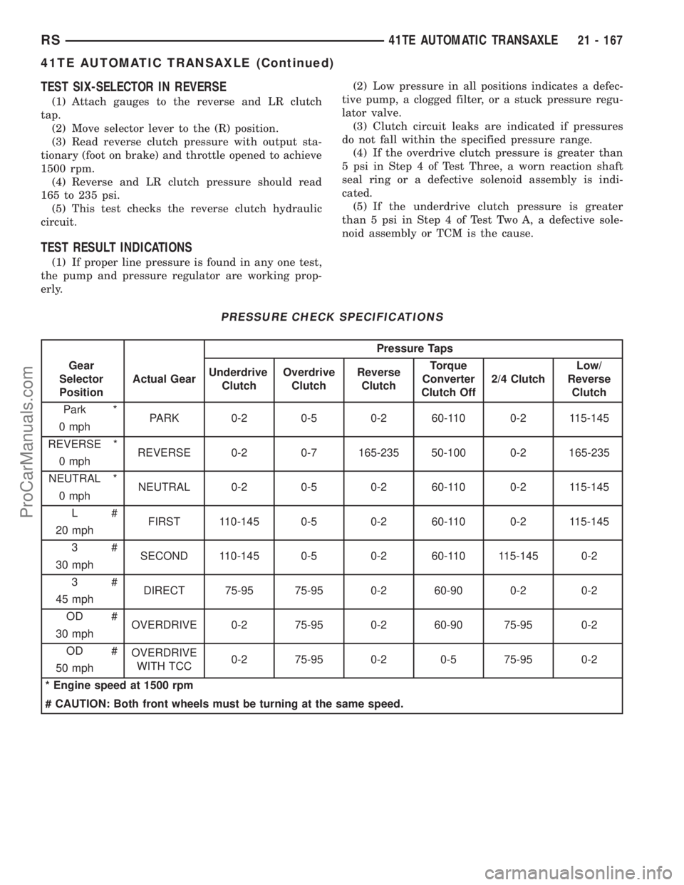
PRESSURE CHECK SPECIFICATIONS
Pressure Taps
Gear
Selector
PositionActual GearUnderdrive
ClutchOverdrive
ClutchReverse
ClutchTorque
Converter
Clutch Off2/4 ClutchLow/
Reverse
Clutch
Park *
PARK 0-2 0-5 0-2 60-110 0-2 115-145
0 mph
REVERSE *
REVERSE 0-2 0-7 165-235 50-100 0-2 165-235
0 mph
NEUTRAL *
NEUTRAL 0-2 0-5 0-2 60-110 0-2 115-145
0 mph
L#
FIRST 110-145 0-5 0-2 60-110 0-2 115-145
20 mph
3#
SECOND 110-145 0-5 0-2 60-110 115-145 0-2
30 mph
3#
DIRECT 75-95 75-95 0-2 60-90 0-2 0-2
45 mph
OD #
OVERDRIVE 0-2 75-95 0-2 60-90 75-95 0-2
30 mph
OD #
OVERDRIVE
WITH TCC0-2 75-95 0-2 0-5 75-95 0-2
50 mph
* Engine speed at 1500 rpm
# CAUTION: Both front wheels must be turning at the same speed.
RS41TE AUTOMATIC TRANSAXLE21 - 167
41TE AUTOMATIC TRANSAXLE (Continued)
ProCarManuals.com
Page 1808 of 2399
(7) Check the transaxle fluid level and add an
appropriate amount to bring the transaxle fluid level
to 3mm (1/8 in.) below the lowest mark on the dip-
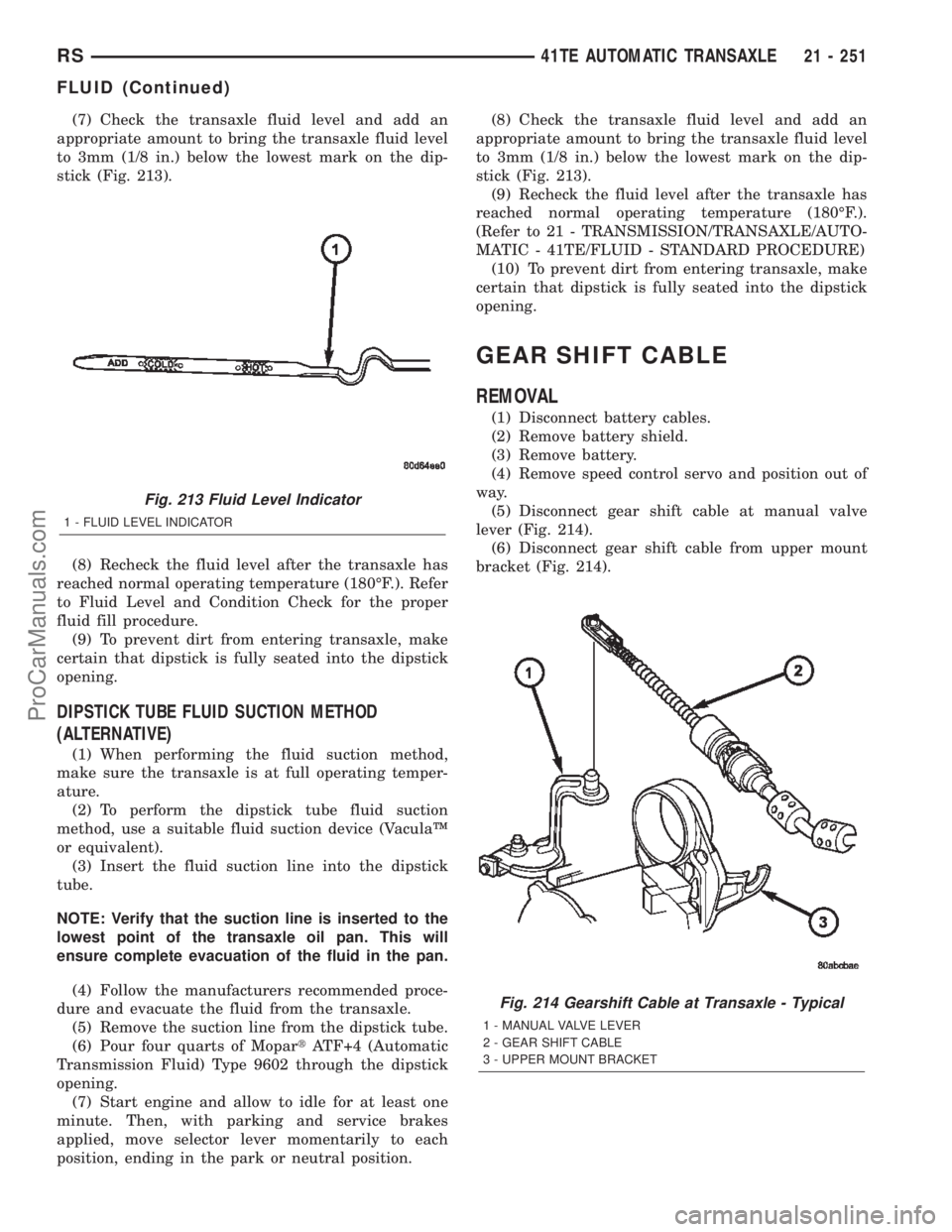
stick (Fig. 213).
(8) Recheck the fluid level after the transaxle has
reached normal operating temperature (180ÉF.). Refer
to Fluid Level and Condition Check for the proper
fluid fill procedure.
(9) To prevent dirt from entering transaxle, make
certain that dipstick is fully seated into the dipstick
opening.
DIPSTICK TUBE FLUID SUCTION METHOD
(ALTERNATIVE)
(1) When performing the fluid suction method,
make sure the transaxle is at full operating temper-
ature.
(2) To perform the dipstick tube fluid suction
method, use a suitable fluid suction device (VaculaŸ
or equivalent).
(3) Insert the fluid suction line into the dipstick
tube.
NOTE: Verify that the suction line is inserted to the
lowest point of the transaxle oil pan. This will
ensure complete evacuation of the fluid in the pan.
(4) Follow the manufacturers recommended proce-
dure and evacuate the fluid from the transaxle.
(5) Remove the suction line from the dipstick tube.
(6) Pour four quarts of MopartATF+4 (Automatic
Transmission Fluid) Type 9602 through the dipstick
opening.
(7) Start engine and allow to idle for at least one
minute. Then, with parking and service brakes
applied, move selector lever momentarily to each
position, ending in the park or neutral position.(8) Check the transaxle fluid level and add an
appropriate amount to bring the transaxle fluid level
to 3mm (1/8 in.) below the lowest mark on the dip-
stick (Fig. 213).
(9) Recheck the fluid level after the transaxle has
reached normal operating temperature (180ÉF.).
(Refer to 21 - TRANSMISSION/TRANSAXLE/AUTO-
MATIC - 41TE/FLUID - STANDARD PROCEDURE)
(10) To prevent dirt from entering transaxle, make
certain that dipstick is fully seated into the dipstick
opening.
GEAR SHIFT CABLE
REMOVAL
(1) Disconnect battery cables.
(2) Remove battery shield.
(3) Remove battery.
(4) Remove speed control servo and position out of
way.
(5) Disconnect gear shift cable at manual valve
lever (Fig. 214).
(6) Disconnect gear shift cable from upper mount
bracket (Fig. 214).
Fig. 213 Fluid Level Indicator
1 - FLUID LEVEL INDICATOR
Fig. 214 Gearshift Cable at Transaxle - Typical
1 - MANUAL VALVE LEVER
2 - GEAR SHIFT CABLE
3 - UPPER MOUNT BRACKET
RS41TE AUTOMATIC TRANSAXLE21 - 251
FLUID (Continued)
ProCarManuals.com
Page 1963 of 2399
Inspect for the following:
²Verify correct (OEM) wheel and tire, as well as
correct wheel weights. Aluminum wheels require
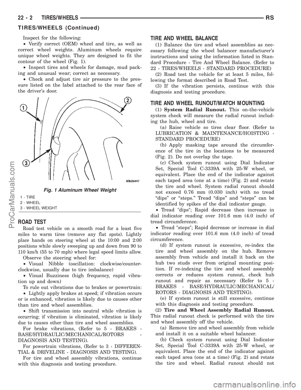
unique wheel weights. They are designed to fit the
contour of the wheel (Fig. 1).
²Inspect tires and wheels for damage, mud pack-
ing and unusual wear; correct as necessary.
²Check and adjust tire air pressure to the pres-
sure listed on the label attached to the rear face of
the driver's door.
ROAD TEST
Road test vehicle on a smooth road for a least five
miles to warm tires (remove any flat spots). Lightly
place hands on steering wheel at the 10:00 and 2:00
positions while slowly sweeping up and down from 90 to
110 km/h (55 to 70 mph) where legal speed limits allow.
Observe the steering wheel for:
²Visual Nibble (oscillation: clockwise/counter-
clockwise, usually due to tire imbalance)
²Visual Buzziness (high frequency, rapid vibra-
tion up and down)
To rule out vibrations due to brakes or powertrain:
²Lightly apply brakes at speed; if vibration occurs
or is enhanced, vibration is likely due to causes other
than tire and wheel assemblies.
²
Shift transmission into neutral while vibration is
occurring; if vibration is eliminated, vibration is likely
due to causes other than tire and wheel assemblies.
For brake vibrations, (Refer to 5 - BRAKES -
BASE/HYDRAULIC/MECHANICAL/ROTORS -
DIAGNOSIS AND TESTING).
For powertrain vibrations, (Refer to 3 - DIFFEREN-
TIAL & DRIVELINE - DIAGNOSIS AND TESTING).
For tire and wheel assembly vibrations, continue
with this diagnosis and testing procedure.
TIRE AND WHEEL BALANCE
(1) Balance the tire and wheel assemblies as nec-
essary following the wheel balancer manufacturer's
instructions and using the information listed in Stan-
dard Procedure - Tire And Wheel Balance. (Refer to
22 - TIRES/WHEELS - STANDARD PROCEDURE)
(2) Road test the vehicle for at least 5 miles, fol-
lowing the format described in Road Test.
(3) If the vibration persists, continue with this
diagnosis and testing procedure.
TIRE AND WHEEL RUNOUT/MATCH MOUNTING
(1)System Radial Runout.This on-the-vehicle
system check will measure the radial runout includ-
ing the hub, wheel and tire.
(a) Raise vehicle so tires clear floor. (Refer to
LUBRICATION & MAINTENANCE/HOISTING -
STANDARD PROCEDURE)
(b) Apply masking tape around the circumfer-
ence of the tire in the locations to be measured
(Fig. 2). Do not overlap the tape.
(c) Check system runout using Dial Indicator
Set, Special Tool C-3339A with 25-W wheel, or
equivalent. Place the end of the indicator against
each taped area (one at a time) (Fig. 2) and rotate
the tire and wheel. System radial runout should
not exceed 0.76 mm (0.030 inch) with no tread
ªdipsº or ªsteps.º Tread ªdipsº and ªstepsº can be
identified by spikes of the dial indicator gauge.
²Tread9dips9; Rapid decrease then increase in
dial indicator reading over 101.6 mm (4.0 inch) of
tread circumference.
²Tread9steps9; Rapid decrease or increase in dial
indicator reading over 101.6 mm (4.0 inch) of tread
circumference.
(d) If system runout is excessive, re-index the
tire and wheel assembly on the hub. Remove
assembly from vehicle and install it back on the
hub two studs over from original mounting posi-
tion. If re-indexing the tire and wheel assembly
corrects or reduces system runout, check hub
runout and repair as necessary (Refer to 5 -
BRAKES - BASE/HYDRAULIC/MECHANICAL/
ROTORS - DIAGNOSIS AND TESTING).
(e) If system runout is still excessive, continue
with this diagnosis and testing procedure.
(2)Tire and Wheel Assembly Radial Runout.
This radial runout check is performed with the tire
and wheel assembly off the vehicle.
(a) Remove tire and wheel assembly from vehicle
and install it on a suitable wheel balancer.
(b) Check system runout using Dial Indicator
Set, Special Tool C-3339A with 25-W wheel, or
equivalent. Place the end of the indicator against
each taped area (one at a time) (Fig. 2) and rotate
the tire and wheel. Radial runout should not
Fig. 1 Aluminum Wheel Weight
1 - TIRE
2 - WHEEL
3 - WHEEL WEIGHT
22 - 2 TIRES/WHEELSRS
TIRES/WHEELS (Continued)
ProCarManuals.com
Page 1996 of 2399
MOPARTSPRAY WHITE LUBE OR EQUIVALENT
²Door Check Straps
²Liftgate Latches
²Liftgate Prop Pivots
²Ash Receiver
²Fuel Filler Door Remote Control Latch Mecha-
nism
²Parking Brake Mechanism
²Sliding Seat Tracks
²Liftgate Latch
MOPARTMultipurpose GREASE OR EQUIVALENT
²All Other Hood Mechanisms
MOPARTLOCK CYLINDER LUBRICANT OR
EQUIVALENT
²Door Lock Cylinders
²Liftgate Lock Cylinder
SPECIAL TOOLS
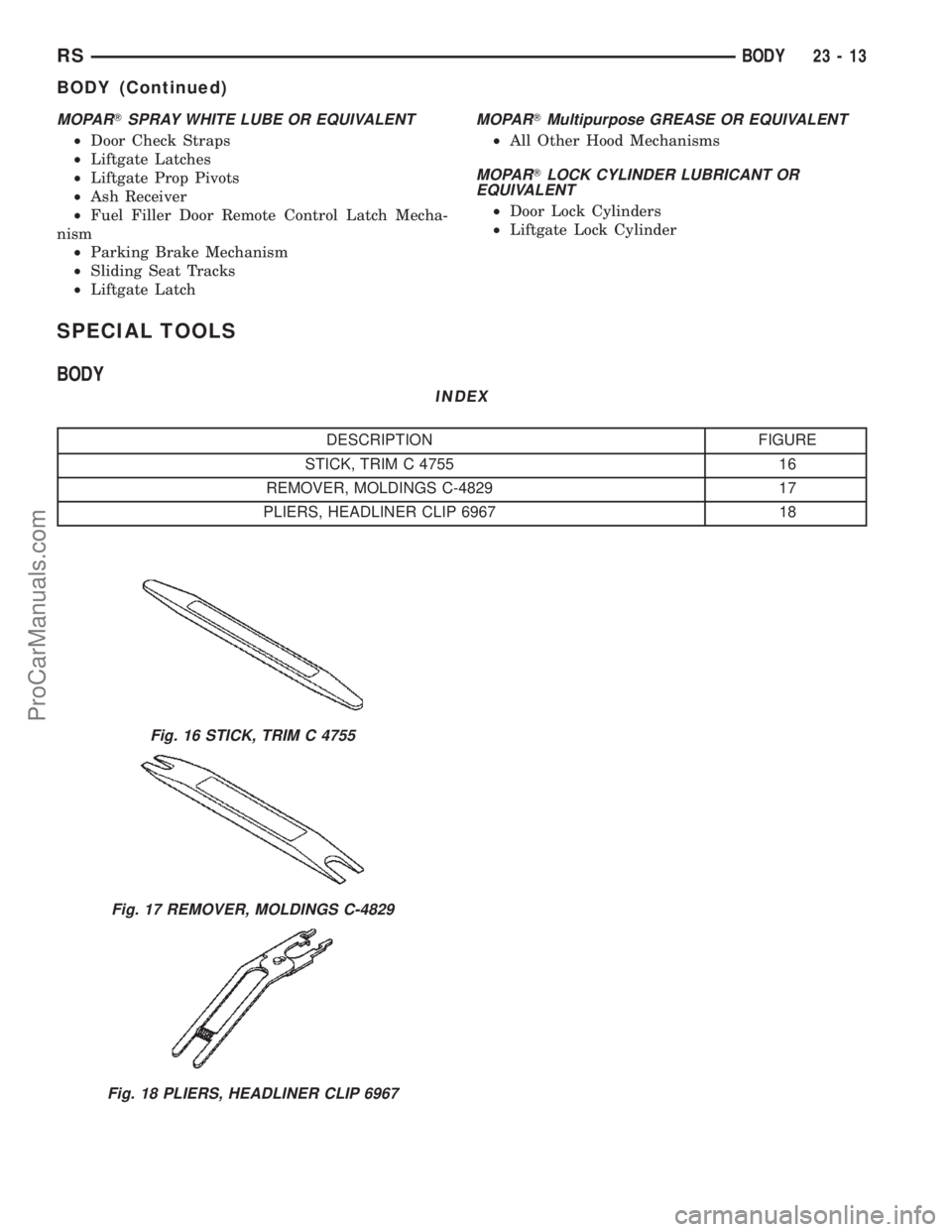
BODY
INDEX
DESCRIPTION FIGURE
STICK, TRIM C 4755 16
REMOVER, MOLDINGS C-4829 17
PLIERS, HEADLINER CLIP 6967 18
Fig. 16 STICK, TRIM C 4755
Fig. 17 REMOVER, MOLDINGS C-4829
Fig. 18 PLIERS, HEADLINER CLIP 6967
RSBODY23-13
BODY (Continued)
ProCarManuals.com
Page 2051 of 2399
(17) Install the screws attaching the instrument
panel reinforcement (Fig. 5).
(18) Connect the shrouds and install the two steer-
ing column shroud retaining screws.
(19) Install five screws to the left under column
instrument panel reinforcement brace.
(20) Install the two screws to the hood release
handle.
(21) Connect the left side wiring:
(a) Brake switch.
(b) Main bulkhead connector.
(c) Five harness connectors.
(d) Driver airbag connector.
(22) Install two screws to the left side instrument
panel silencer (Fig. 4).
(23) Clip the Data Link Connector (DLC) to the
steering column backing plate.
(24) Install the eight screws to the steering column
backing plate.
(25) Install the four screws to the lower steering
column cover.
(26) Install the glove box:
(a) Install glove box into the vehicle. Line up the
hinges and firmly snap together.
(b) Push in on sides of glove box bin and raise
door.
(27) Install the both left and right side A-pillar
trim covers. Position trim cover over slots and firmly
snap into place.
(28) Install the two screws to each right and left
cowl trim covers.
(29) Connect the wire connectors to the Passenger
Airbag.
(30) Install the bolts attaching the lower supports
to the floor pan.
(31) Install the bolts attaching the lower supports
to the instrument panel frame (Fig. 3).
(32) Install the lower console:
(a) Install lower console to vehicle.
(b) Connect the auxiliary power outlet.
(c) Install the six retaining screws.
(33) Connect the battery negative cable.
INSTRUMENT PANEL CENTER
BEZEL
REMOVAL
(1) Disconnect and isolate the battery negative
cable.
(2) Insert the trim stick (special tool #C-4755) or
equivalent between access cover and center bezel
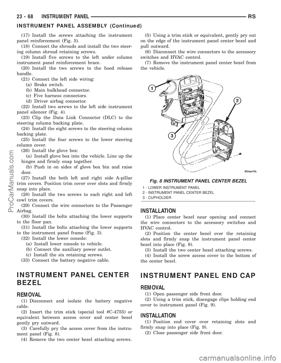
gently pry outward.
(3) Carefully pry the access cover from the instru-
ment panel (Fig. 8).
(4) Remove the two center bezel attaching screws.(5) Using a trim stick or equivalent, gently pry out
on the edge of the instrument panel center bezel and
pull outward.
(6) Disconnect the wire connectors to the accessory
switches and HVAC control.
(7) Remove the instrument panel center bezel from
the vehicle.
INSTALLATION
(1) Place center bezel near opening and connect
the wire connectors to the accessory switches and
HVAC control.
(2) Position the center bezel over the retaining
slots and firmly snap the instrument panel center
bezel into place (Fig. 8).
(3) Install the two center bezel attaching screws.
(4) Install the screw access cover to the bottom of
the center bezel.
INSTRUMENT PANEL END CAP
REMOVAL
(1) Open passenger side front door.
(2) Using a trim stick, disengage clips holding end
cover to instrument panel (Fig. 9).
INSTALLATION
(1) Position end cover over retaining slots and
firmly snap into place (Fig. 9).
(2) Close passenger side front door.
Fig. 8 INSTRUMENT PANEL CENTER BEZEL
1 - LOWER INSTRUMENT PANEL
2 - INSTRUMENT PANEL CENTER BEZEL
3 - CUPHOLDER
23 - 68 INSTRUMENT PANELRS
INSTRUMENT PANEL ASSEMBLY (Continued)
ProCarManuals.com
Page 2364 of 2399
is enabled to run another test during that trip. When
the test fails 6 times, the counter increments to 3, a
malfunction is entered, and a Freeze Frame is stored,
the code is matured and the MIL is illuminated. If
the first test passes, no further testing is conducted
during that trip.
The MIL is extinguished after three consecutive
good trips. The good trip criteria for the catalyst
monitor is more stringent than the failure criteria. In
order to pass the test and increment one good trip,
the downstream sensor switch rate must be less than
45% of the upstream rate. The failure percentages
are 59% respectively.
Enabling ConditionsÐThe following conditions
must typically be met before the PCM runs the cat-
alyst monitor. Specific times for each parameter may
be different from engine to engine.
²Accumulated drive time
²Enable time
²Ambient air temperature
²Barometric pressure
²Catalyst warm-up counter
²Engine coolant temperature
²Vehicle speed
²MAP
²RPM
²Engine in closed loop
²Fuel level
Pending ConditionsÐ
²Misfire DTC
²Front Oxygen Sensor Response
²Front Oxygen Sensor Heater Monitor
²Front Oxygen Sensor Electrical
²Rear Oxygen Sensor Rationality (middle check)
²Rear Oxygen Sensor Heater Monitor
²Rear Oxygen Sensor Electrical
²Fuel System Monitor
²All TPS faults
²All MAP faults
²All ECT sensor faults
²Purge flow solenoid functionality
²Purge flow solenoid electrical
²All PCM self test faults
²All CMP and CKP sensor faults
²All injector and ignition electrical faults
²Idle Air Control (IAC) motor functionality
²Vehicle Speed Sensor
²Brake switch (auto trans only)
²Intake air temperature
ConflictÐThe catalyst monitor does not run if any
of the following are conditions are present:
²EGR Monitor in progress (if equipped)
²Fuel system rich intrusive test in progress
²EVAP Monitor in progress
²Time since start is less than 60 seconds
²Low fuel level-less than 15 %²Low ambient air temperature
²Ethanel content learn is takeng place and the
ethenal used once flag is set
SuspendÐThe Task Manager does not mature a
catalyst fault if any of the following are present:
²Oxygen Sensor Monitor, Priority 1
²Oxygen Sensor Heater, Priority 1
²EGR Monitor, Priority 1 (if equipped)
²EVAP Monitor, Priority 1
²Fuel System Monitor, Priority 2
²Misfire Monitor, Priority 2
OPERATION - NON-MONITORED CIRCUITS
The PCM does not monitor all circuits, systems
and conditions that could have malfunctions causing
driveability problems. However, problems with these
systems may cause the PCM to store diagnostic trou-
ble codes for other systems or components. For exam-
ple, a fuel pressure problem will not register a fault
directly, but could cause a rich/lean condition or mis-
fire. This could cause the PCM to store an oxygen
sensor or misfire diagnostic trouble code.
The major non-monitored circuits are listed below
along with examples of failures modes that do not
directly cause the PCM to set a DTC, but for a sys-
tem that is monitored.
FUEL PRESSURE
The fuel pressure regulator controls fuel system
pressure. The PCM cannot detect a clogged fuel
pump inlet filter, clogged in-line fuel filter, or a
pinched fuel supply or return line. However, these
could result in a rich or lean condition causing the
PCM to store an oxygen sensor, fuel system, or mis-
fire diagnostic trouble code.
SECONDARY IGNITION CIRCUIT
The PCM cannot detect an inoperative ignition coil,
fouled or worn spark plugs, ignition cross firing, or
open spark plug cables. The misfire will however,
increase the oxygen content in the exhaust, deceiving
the PCM in to thinking the fuel system is too lean.
Also misfire detection.
CYLINDER COMPRESSION
The PCM cannot detect uneven, low, or high engine
cylinder compression. Low compression lowers O2
content in the exhaust. Leading to fuel system, oxy-
gen sensor, or misfire detection fault.
EXHAUST SYSTEM
The PCM cannot detect a plugged, restricted or
leaking exhaust system. It may set a EGR (if
equipped) or Fuel system or O2S fault.
RSEMISSIONS CONTROL25-5
EMISSIONS CONTROL (Continued)
ProCarManuals.com
Page 2390 of 2399
EXHAUST GAS RECIRCULATION
TABLE OF CONTENTS
page page
EXHAUST GAS RECIRCULATION
DESCRIPTION..........................3
OPERATION............................3
VA LV E
DESCRIPTION..........................3
OPERATION............................3REMOVAL.............................4
INSTALLATION..........................4
VALVE COOLER
DESCRIPTION..........................4
REMOVAL.............................4
INSTALLATION..........................5
EXHAUST GAS
RECIRCULATION
DESCRIPTION
The EGR system reduces oxides of nitrogen (NOx)
in the engine exhaust. This is accomplished by allow-
ing a predetermined amount of hot exhaust gas to
recirculate and dilute the incoming fuel/air mixture.
A malfunctioning EGR system can cause engine
stumble, sags, or hesitation, rough idle, engine stall-
ing and poor driveability.
OPERATION
The system consists of:
²An EGR valve assembly. The valve is located on
the rear of the engine above the exhaust manfiold.
²An EGR solenoid.The EGR solenoid controls the
ªon timeº of the EGR valve.
²The ECM operates the EGR solenoid. The ECM
is located inside the vehicle under the instrument
panel.
²An EGR tube connects a passage in the EGR
valve to the rear of the exhaust manifold.
²The vacuum pump supplies vacuum for the EGR
solenoid and the EGR valve. This pump also supplies
vacuum for operation of the power brake boosterb
and the heating and air conditioning system. The
pump is located internally in the front of the engine
block and is driven by the crankshaft gear.²Vacuum lines and hoses connect the various
components.
When the ECM supplies a variable ground signal
to the EGR solenoid, EGR system operation starts to
occur. The ECM will monitor and determine when to
supply and remove this variable ground signal. This
will depend on inputs from the engine coolant tem-
perature, throttle position and engine speed sensors.
When the variable ground signal is supplied to the
EGR solenoid, vacuum from the vacuum pump will
be allowed to pass through the EGR solenoid and on
to the EGR valve with a connecting hose.
Exhaust gas recirculation will begin in this order
when:
²The ECM determines that EGR system opera-
tion is necessary.
²The engine is running to operate the vacuum
pump.
²A variable ground signal is supplied to the EGR
solenoid.
²Variable vacuum passes through the EGR sole-
noid to the EGR valve.
²The inlet seat (poppet valve) at the bottom of
the EGR valve opens to dilute and recirculate
exhaust gas back into the intake manifold.
The EGR system will be shut down by the ECM
after 60 seconds of continuous engine idling to
improve idle quality.
RGEXHAUST GAS RECIRCULATION25a-3
ProCarManuals.com