2002 CHRYSLER VOYAGER Brake line
[x] Cancel search: Brake linePage 1366 of 2399
(17) Remove battery shield.
(18) Remove charge air cooler outlet hose.
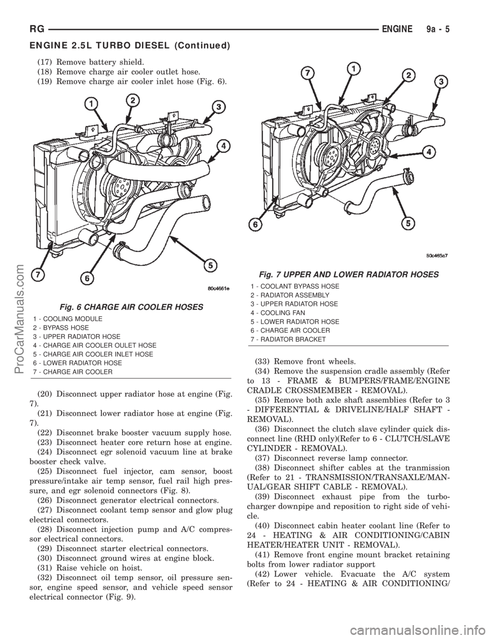
(19) Remove charge air cooler inlet hose (Fig. 6).
(20) Disconnect upper radiator hose at engine (Fig.
7).
(21) Disconnect lower radiator hose at engine (Fig.
7).
(22) Disconnet brake booster vacuum supply hose.
(23) Disconnect heater core return hose at engine.
(24) Disconnect egr solenoid vacuum line at brake
booster check valve.
(25) Disconnect fuel injector, cam sensor, boost
pressure/intake air temp sensor, fuel rail high pres-
sure, and egr solenoid connectors (Fig. 8).
(26) Disconnect generator electrical connectors.
(27) Disconnect coolant temp sensor and glow plug
electrical connectors.
(28) Disconnect injection pump and A/C compres-
sor electrical connectors.
(29) Disconnect starter electrical connectors.
(30) Disconnect ground wires at engine block.
(31) Raise vehicle on hoist.
(32) Disconnect oil temp sensor, oil pressure sen-
sor, engine speed sensor, and vehicle speed sensor
electrical connector (Fig. 9).(33) Remove front wheels.
(34) Remove the suspension cradle assembly (Refer
to 13 - FRAME & BUMPERS/FRAME/ENGINE
CRADLE CROSSMEMBER - REMOVAL).
(35) Remove both axle shaft assemblies (Refer to 3
- DIFFERENTIAL & DRIVELINE/HALF SHAFT -
REMOVAL).
(36) Disconnect the clutch slave cylinder quick dis-
connect line (RHD only)(Refer to 6 - CLUTCH/SLAVE
CYLINDER - REMOVAL).
(37) Disconnect reverse lamp connector.
(38) Disconnect shifter cables at the tranmission
(Refer to 21 - TRANSMISSION/TRANSAXLE/MAN-
UAL/GEAR SHIFT CABLE - REMOVAL).
(39) Disconnect exhaust pipe from the turbo-
charger downpipe and reposition to right side of vehi-
cle.
(40) Disconnect cabin heater coolant line (Refer to
24 - HEATING & AIR CONDITIONING/CABIN
HEATER/HEATER UNIT - REMOVAL).
(41) Remove front engine mount bracket retaining
bolts from lower radiator support
(42) Lower vehicle. Evacuate the A/C system
(Refer to 24 - HEATING & AIR CONDITIONING/
Fig. 6 CHARGE AIR COOLER HOSES
1 - COOLING MODULE
2 - BYPASS HOSE
3 - UPPER RADIATOR HOSE
4 - CHARGE AIR COOLER OULET HOSE
5 - CHARGE AIR COOLER INLET HOSE
6 - LOWER RADIATOR HOSE
7 - CHARGE AIR COOLER
Fig. 7 UPPER AND LOWER RADIATOR HOSES
1 - COOLANT BYPASS HOSE
2 - RADIATOR ASSEMBLY
3 - UPPER RADIATOR HOSE
4 - COOLING FAN
5 - LOWER RADIATOR HOSE
6 - CHARGE AIR COOLER
7 - RADIATOR BRACKET
RGENGINE9a-5
ENGINE 2.5L TURBO DIESEL (Continued)
ProCarManuals.com
Page 1368 of 2399
INSTALLATION
INSTALLATION - 2.5L TURBO DIESEL ENGINE
(1) Reassembly engine and transmission assembly
and install on engine cradle.
(2) Position engine and cradle assembly under
vehicle.
(3) Slowly lower the vehicle down over the engine
and cradle assembly.
(4) Install right engine mount bolts. Torque to
54N´m (40 ft. lbs.)
(5) Install left engine mount through bolt. Torque
to 75N´m (55 ft. lbs.)
(6) Raise vehicle and engine from engine cradle.
(7) Attach front engine mount bracket to lower
radiator support. Torque to 54N´m (40 ft. lbs.)
(8) Connect cabin heater coolant hose.
(9) Connect exhaust pipe to the turbocharger
downpipe flange. Torque to 28 N´m (250 in. lbs.)
(10) Connect reverse lamp electrical connector at
transmission.
(11) Connect both shifter cables (Refer to 21 -
TRANSMISSION/TRANSAXLE/MANUAL/GEAR
SHIFT CABLE - INSTALLATION).
(12) Connect the clutch slave cylinder quick dis-
connect connector (RHD only)(Refer to 6 - CLUTCH/
SLAVE CYLINDER - INSTALLATION).
(13) Install engine harness into bracket on trans-
mission.
(14) Lower vehicle.
(15) Connect fuel supply and return lines.
(16) Connect A/C lines to A/C compressor. Torque
to 23N´m (17 ft. lbs.)
(17) Route engine wiring harnes to proper location.
(18) Connect engine harness ground cables to
engine block
(19) Connect starter solenoid electrical connector
and battery feed wire to starter. Torque to 10N´m (90
in. lbs.)
(20) Connect A/C compressor, injection pump, glow
plugs, and coolant temperature sensor electrical con-
nectors.
(21) Connect generator electrical connector. Torque
to 9N´m (75 in. lbs.)
(22) Connect the fuel injector, fuel pressure sensor,
boost pressure/intake air temp sensor, cam sensor,
and egr solenoid electrical connectors (Fig. 8).
(23) Connect egr solenoid vacuum supply line to
brake boost vacuum supply line.(24) Connect brake booster vacuum supply line.
(25) Connect heater core return hose to coolant
pipe.
(26) Connect lower radiator hose to engine (Fig. 7).
(27) Install charger air cooler inlet hose (Fig. 6).
(28) Install charge air cooler outlet hose (Fig. 6).
(29) Connect upper radiator hose to engine (Fig.
7).
(30) Install battery shield.
(31) Install coolant reserve pressure container
(Refer to 7 - COOLING/ENGINE/COOLANT RECOV-
ERY PRESS CONTAINER - INSTALLATION).
(32) Install power steering reservoir and bracket
(Fig. 4).
(33) Raise vehicle
(34) Connect oil pressure sensor, oil temperature
sensor, engine speed sensor, and vehicle speed sensor
electrical connector (Fig. 9).
(35) Install suspension cradle in vehicle (Refer to
13 - FRAME & BUMPERS/FRAME/ENGINE CRA-
DLE CROSSMEMBER - INSTALLATION).
(36) Install both axle shaft assemblies (Refer to 3 -
DIFFERENTIAL & DRIVELINE/HALF SHAFT -
INSTALLATION).
(37) Connect the power steering supply, pressure,
and return lines to power steering pump (Fig. 4).
(38) Install the power steering line brackets on oil
pan (Fig. 4).
(39) Install lower splash shield and side panels.
(40) Install both front wheel and tire assemblies.
(41) Lower vehicle.
(42) Install air cleaner housing, MAF sensor, and
air intake tube assembly (Fig. 3).
(43) Refill transmission to proper level (Refer to 21
- TRANSMISSION/TRANSAXLE/MANUAL/FLUID -
STANDARD PROCEDURE).
(44) Refill engine coolant (Refer to 7 - COOLING/
ENGINE/COOLANT - STANDARD PROCEDURE).
(45) Recharge A/C system (Refer to 24 - HEATING
& AIR CONDITIONING/PLUMBING/REFRIGER-
ANT - STANDARD PROCEDURE) .
(46) Install engine cover (Refer to 9 - ENGINE -
INSTALLATION) (Fig. 2).
(47) Connect negative battery cable.
INSTALLATION - ENGINE COVER
(1) Install engine cover on engine.
(2) Install the engine cover mounting bolts (Fig.
10).
RGENGINE9a-7
ENGINE 2.5L TURBO DIESEL (Continued)
ProCarManuals.com
Page 1449 of 2399
REMOVAL
The front cradle crossmember must be installed in
the design location to achieve proper front end sus-
pension alignment. If the cradle crossmember is
removed without applying reference marks on the
frame rails, align the cradle crossmember according
to the dimensions provided in this group.
NOTE: If the caged nuts in the frame rails become
damaged and cannot be reused, a replacement nut
can be obtained through MoparT.
REMOVAL
(1) Disconnect battery negative cable.
(2) Remove steering column lower cover from
instrument panel (Refer to 23 - BODY/INSTRU-
MENT PANEL/STEERING COLUMN OPENING
COVER - REMOVAL).
(3) Remove steering column cover backing plate
(Refer to 23 - BODY/INSTRUMENT PANEL/STEER-
ING COLUMN COVER BACKING PLATE - REMOV-
AL).
(4) Position steering so front wheels are straight
ahead.
CAUTION: Do not rotate steering wheel after disen-
gaging lower coupling from steering gear, damage
to air bag clock spring can result.
(5) Remove clinch bolt attaching steering column
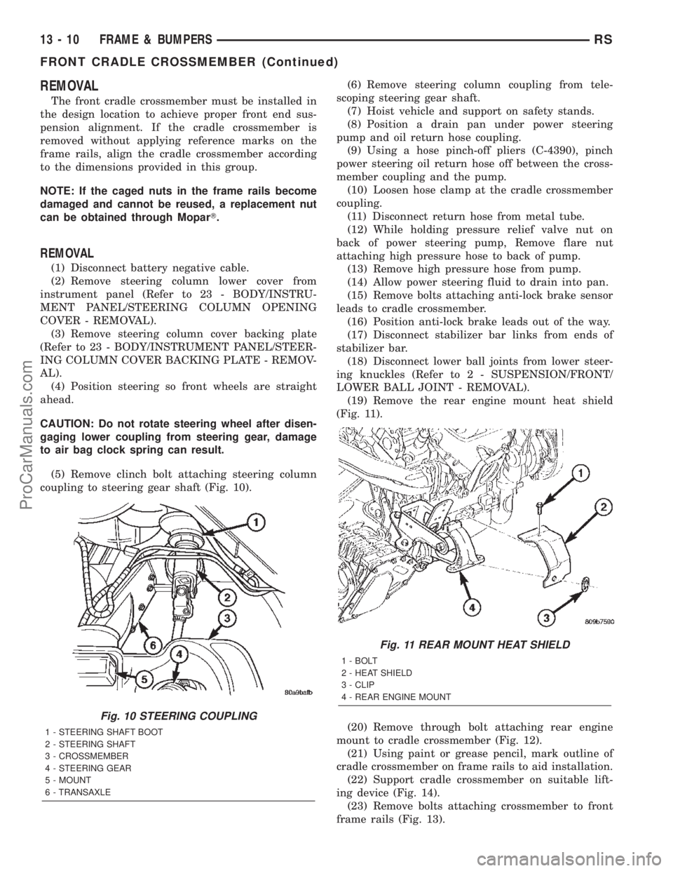
coupling to steering gear shaft (Fig. 10).(6) Remove steering column coupling from tele-
scoping steering gear shaft.
(7) Hoist vehicle and support on safety stands.
(8) Position a drain pan under power steering
pump and oil return hose coupling.
(9) Using a hose pinch-off pliers (C-4390), pinch
power steering oil return hose off between the cross-
member coupling and the pump.
(10) Loosen hose clamp at the cradle crossmember
coupling.
(11) Disconnect return hose from metal tube.
(12) While holding pressure relief valve nut on
back of power steering pump, Remove flare nut
attaching high pressure hose to back of pump.
(13) Remove high pressure hose from pump.
(14) Allow power steering fluid to drain into pan.
(15) Remove bolts attaching anti-lock brake sensor
leads to cradle crossmember.
(16) Position anti-lock brake leads out of the way.
(17) Disconnect stabilizer bar links from ends of
stabilizer bar.
(18) Disconnect lower ball joints from lower steer-
ing knuckles (Refer to 2 - SUSPENSION/FRONT/
LOWER BALL JOINT - REMOVAL).
(19) Remove the rear engine mount heat shield
(Fig. 11).
(20) Remove through bolt attaching rear engine
mount to cradle crossmember (Fig. 12).
(21) Using paint or grease pencil, mark outline of
cradle crossmember on frame rails to aid installation.
(22) Support cradle crossmember on suitable lift-
ing device (Fig. 14).
(23) Remove bolts attaching crossmember to front
frame rails (Fig. 13).
Fig. 10 STEERING COUPLING
1 - STEERING SHAFT BOOT
2 - STEERING SHAFT
3 - CROSSMEMBER
4 - STEERING GEAR
5 - MOUNT
6 - TRANSAXLE
Fig. 11 REAR MOUNT HEAT SHIELD
1 - BOLT
2 - HEAT SHIELD
3 - CLIP
4 - REAR ENGINE MOUNT
13 - 10 FRAME & BUMPERSRS
FRONT CRADLE CROSSMEMBER (Continued)
ProCarManuals.com
Page 1451 of 2399
INSTALLATION
NOTE: If cradle crossmember requires replacement.
Refer to Group 2, Suspension, to transfer suspen-
sion components and Group 19, Steering, to trans-
fer steering components.
(1) Support crossmember on suitable lifting device
(Fig. 14).
(2) Position crossmember to vehicle.
(3) Loosely install bolts attaching cradle cross-
member to front frame rails.
(4) Align crossmember to previously made marks
on frame rails.
(5) Tighten bolts attaching cradle crossmember to
frame rails.
(6) Install through bolt attaching rear engine
mount to cradle crossmember (Fig. 12) and tighten to
68 N´m (50 ft. lbs.) torque.
(7) Install the rear mount heat shield (Fig. 11).
(8) Connect lower ball joints to steering knuckles
(Refer to 2 - SUSPENSION/FRONT/LOWER BALL
JOINT - INSTALLATION)
(9) Connect stabilizer bar links to ends of stabi-
lizer bar.
(10) Install bolts attaching anti-lock brake sensor
leads to cradle crossmember.
(11) Install high pressure hose to pump.
(12) Connect return hose to metal tube.
(13) Tighten hose clamp at the cradle crossmember
coupling.
(14) Remove pinch-off pliers.
(15) Position steering so front wheels are straight
ahead.
(16) Install steering column coupling to telescoping
steering gear shaft.
(17) Install clinch bolt attaching steering column
coupling to steering gear shaft.
(18) Install steering column cover backing plate
(Refer to 23 - BODY/INSTRUMENT PANEL/STEER-
ING COLUMN COVER BACKING PLATE -
INSTALLATION)
(19) Install steering column lower cover from
instrument panel (Refer to 23 - BODY/INSTRU-MENT PANEL/STEERING COLUMN OPENING
COVER - INSTALLATION).
(20) Connect battery negative cable.
FRONT CROSSMEMBER
MOUNT BUSHINGS
REMOVAL
(1) Using paint or grease pencil, mark outline of
cradle crossmember on frame rails.
(2) Loosen bolts attaching crossmember to frame
rails.
(3) Remove bolt on bushing that requires replace-
ment.
(4) Allow cradle crossmember to drop down enough
to gain clearance for bushing removal.
(5) Remove bushing from vehicle.
INSTALLATION
(1) Apply rubber lubrication or soap to replace-
ment bushing.
(2) Insert lower half of bushing into square hole in
cradle crossmember.
(3) Place upper half of bushing on top of cross-
member aligned to receive square tube protruding
upward from lower bushing half.
(4) Squeeze bushing halves together to ensure they
are properly mated.
(5) Lift cradle crossmember upward to close gap
between the bushing and frame.
(6) Verify that lower bushing is fully seated into
cradle crossmember and upper bushing.
(7) Install bolt attaching bushing and crossmember
to frame rail hand tight.
(8) Align cradle crossmember to reference marks
on frame rails.
(9) Tighten cradle crossmember to frame rails
attaching bolts to 163 N´m (120 ft. lbs.) torque.
13 - 12 FRAME & BUMPERSRS
FRONT CRADLE CROSSMEMBER (Continued)
ProCarManuals.com
Page 1521 of 2399
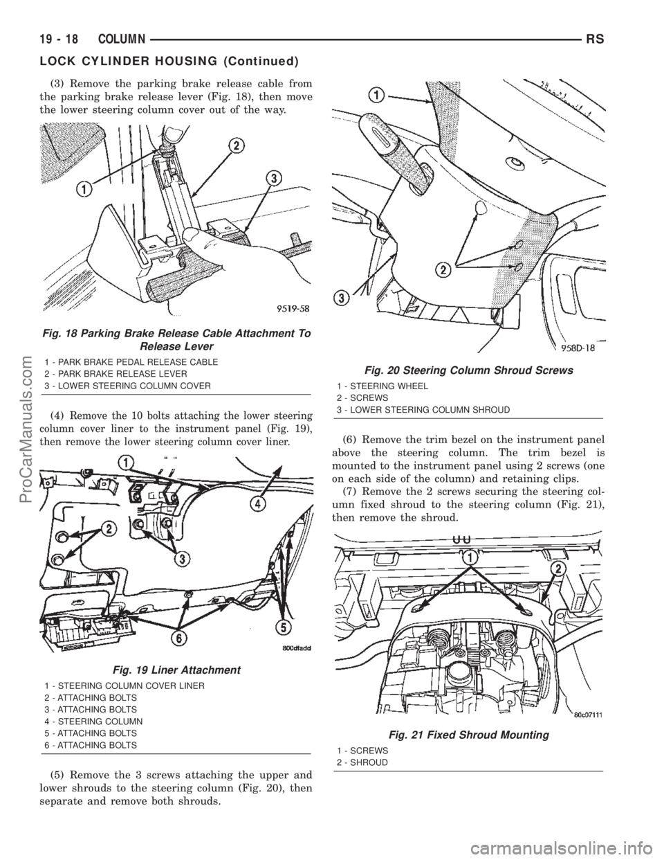
(3) Remove the parking brake release cable from
the parking brake release lever (Fig. 18), then move
the lower steering column cover out of the way.
(4)
Remove the 10 bolts attaching the lower steering
column cover liner to the instrument panel (Fig. 19),
then remove the lower steering column cover liner.
(5) Remove the 3 screws attaching the upper and
lower shrouds to the steering column (Fig. 20), then
separate and remove both shrouds.(6) Remove the trim bezel on the instrument panel
above the steering column. The trim bezel is
mounted to the instrument panel using 2 screws (one
on each side of the column) and retaining clips.
(7) Remove the 2 screws securing the steering col-
umn fixed shroud to the steering column (Fig. 21),
then remove the shroud.
Fig. 18 Parking Brake Release Cable Attachment To
Release Lever
1 - PARK BRAKE PEDAL RELEASE CABLE
2 - PARK BRAKE RELEASE LEVER
3 - LOWER STEERING COLUMN COVER
Fig. 19 Liner Attachment
1 - STEERING COLUMN COVER LINER
2 - ATTACHING BOLTS
3 - ATTACHING BOLTS
4 - STEERING COLUMN
5 - ATTACHING BOLTS
6 - ATTACHING BOLTS
Fig. 20 Steering Column Shroud Screws
1 - STEERING WHEEL
2 - SCREWS
3 - LOWER STEERING COLUMN SHROUD
Fig. 21 Fixed Shroud Mounting
1 - SCREWS
2 - SHROUD
19 - 18 COLUMNRS
LOCK CYLINDER HOUSING (Continued)
ProCarManuals.com
Page 1524 of 2399
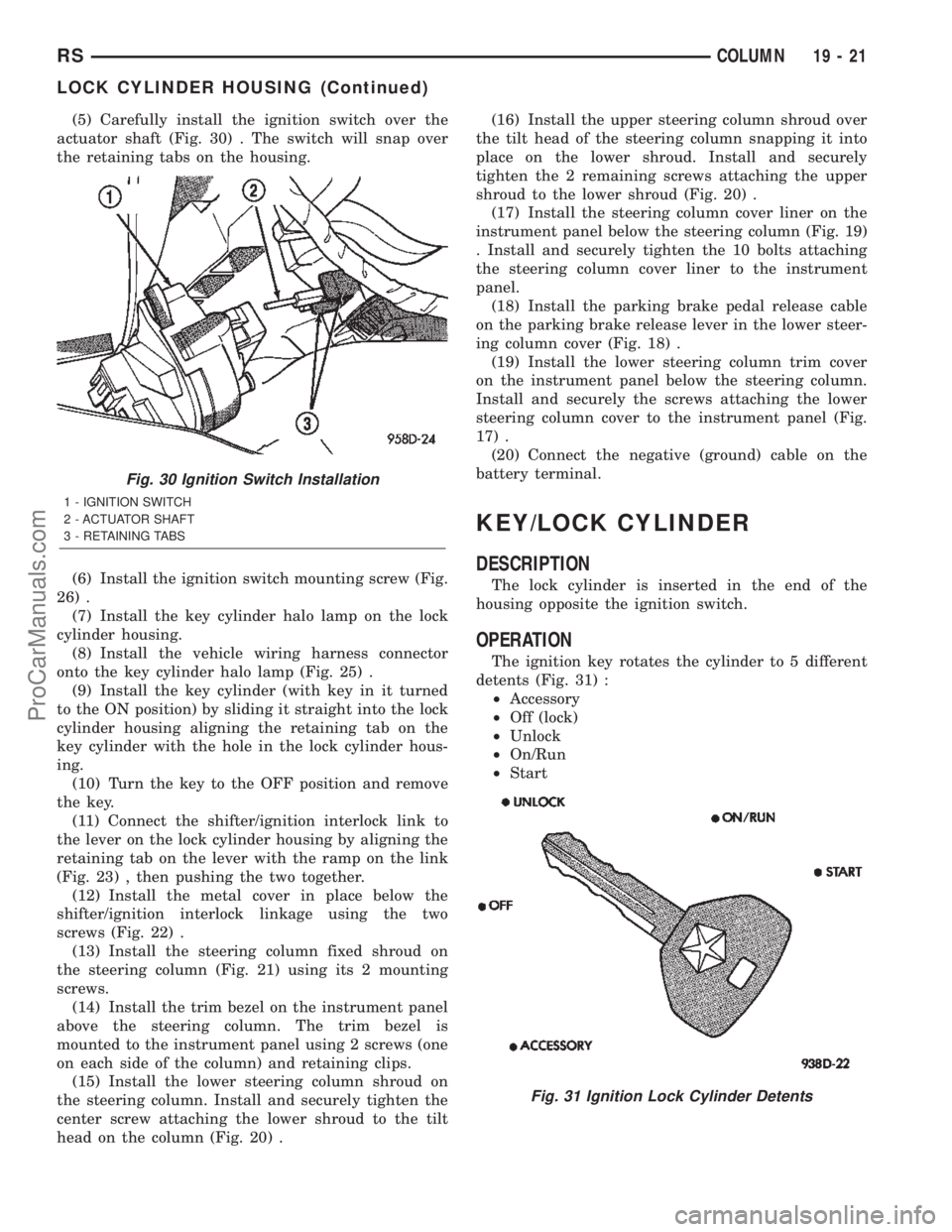
(5) Carefully install the ignition switch over the
actuator shaft (Fig. 30) . The switch will snap over
the retaining tabs on the housing.
(6) Install the ignition switch mounting screw (Fig.
26) .
(7) Install the key cylinder halo lamp on the lock
cylinder housing.
(8) Install the vehicle wiring harness connector
onto the key cylinder halo lamp (Fig. 25) .
(9) Install the key cylinder (with key in it turned
to the ON position) by sliding it straight into the lock
cylinder housing aligning the retaining tab on the
key cylinder with the hole in the lock cylinder hous-
ing.
(10) Turn the key to the OFF position and remove
the key.
(11) Connect the shifter/ignition interlock link to
the lever on the lock cylinder housing by aligning the
retaining tab on the lever with the ramp on the link
(Fig. 23) , then pushing the two together.
(12) Install the metal cover in place below the
shifter/ignition interlock linkage using the two
screws (Fig. 22) .
(13) Install the steering column fixed shroud on
the steering column (Fig. 21) using its 2 mounting
screws.
(14) Install the trim bezel on the instrument panel
above the steering column. The trim bezel is
mounted to the instrument panel using 2 screws (one
on each side of the column) and retaining clips.
(15) Install the lower steering column shroud on
the steering column. Install and securely tighten the
center screw attaching the lower shroud to the tilt
head on the column (Fig. 20) .(16) Install the upper steering column shroud over
the tilt head of the steering column snapping it into
place on the lower shroud. Install and securely
tighten the 2 remaining screws attaching the upper
shroud to the lower shroud (Fig. 20) .
(17) Install the steering column cover liner on the
instrument panel below the steering column (Fig. 19)
. Install and securely tighten the 10 bolts attaching
the steering column cover liner to the instrument
panel.
(18) Install the parking brake pedal release cable
on the parking brake release lever in the lower steer-
ing column cover (Fig. 18) .
(19) Install the lower steering column trim cover
on the instrument panel below the steering column.
Install and securely the screws attaching the lower
steering column cover to the instrument panel (Fig.
17) .
(20) Connect the negative (ground) cable on the
battery terminal.
KEY/LOCK CYLINDER
DESCRIPTION
The lock cylinder is inserted in the end of the
housing opposite the ignition switch.
OPERATION
The ignition key rotates the cylinder to 5 different
detents (Fig. 31) :
²Accessory
²Off (lock)
²Unlock
²On/Run
²Start
Fig. 30 Ignition Switch Installation
1 - IGNITION SWITCH
2 - ACTUATOR SHAFT
3 - RETAINING TABS
Fig. 31 Ignition Lock Cylinder Detents
RSCOLUMN19-21
LOCK CYLINDER HOUSING (Continued)
ProCarManuals.com
Page 1579 of 2399
ASSEMBLY...........................115
SHIFT INTERLOCK SOLENOID
DESCRIPTION........................115
OPERATION..........................115
DIAGNOSIS AND TESTING - BRAKE/
TRANSMISSION SHIFT INTERLOCK
SOLENOID..........................117
REMOVAL............................117
INSTALLATION........................118
SOLENOID - TCC
DESCRIPTION........................119
OPERATION..........................119
REMOVAL............................119
INSTALLATION........................120
THROTTLE VALVE CABLE
REMOVAL............................120
INSTALLATION........................121
ADJUSTMENTS
THROTTLE VALVE LINKAGE
ADJUSTMENT.......................122
TORQUE CONVERTER
DESCRIPTION........................122
OPERATION..........................126
REMOVAL............................127
INSTALLATION........................127
TRANSFER SYSTEM - OUTPUT SHAFT/GEAR/
BEARING
REMOVAL............................128INSTALLATION........................131
ADJUSTMENTS
ADJUSTMENT - OUTPUT SHAFT BEARING . 135
TRANSFER SYSTEM - TRANSFER SHAFT/
GEAR/BEARING
REMOVAL............................137
INSTALLATION........................141
ADJUSTMENTS
ADJUSTMENT - TRANSFER SHAFT
BEARING...........................145
VALVE BODY
REMOVAL............................146
DISASSEMBLY........................148
CLEANING...........................154
INSPECTION.........................155
ASSEMBLY...........................155
INSTALLATION........................158
ADJUSTMENTS
HYDRAULIC CONTROL PRESSURE
ADJUSTMENTS......................160
VEHICLE SPEED SENSOR/PINION GEAR
REMOVAL............................160
INSTALLATION........................160
31TH AUTOMATIC
TRANSAXLE
DESCRIPTION
This transaxle combines torque converter, three
speed transmission, final drive gearing, and differen-
tial into a front wheel drive system.
Within this transaxle, there are three primary
areas:
(1) Main center line plus valve body.
(2) Transfer shaft center line (includes governor
and parking sprag).
(3) Differential center line.
Center distances between the main rotating parts
in these three areas are held precise to maintain a
low noise level.
The torque converter, transaxle area, and differen-
tial are housed in an integral aluminum die casting.
The differential oil sump is common with the
transaxle sump. Separate filling of the differen-
tial is NOT necessary.
The torque converter is attached to the crankshaft
through a flexible driving plate. Cooling of the con-
verter is accomplished by circulating the transaxle
fluid through a remote cooler. There are two types of
coolers used. An oil-to-water type cooler located in
the radiator side tank and/or an oil-to-air heatexchanger. The torque converter assembly is a sealed
unit that cannot be disassembled.
The transaxle fluid is filtered by an internal filter
attached to the lower side of the valve body assembly.
Engine torque is transmitted to the torque con-
verter and then through the input shaft to multiple-
disc clutches in the transaxle. The power flow
depends on the application of the clutches and bands.
Refer to Elements in Use Chart in Diagnosis and
Tests section.
The transaxle consists of:
²Two multiple-disc clutches
²An overrunning clutch
²Two servos
²A hydraulic accumulator
²Two bands
²Two planetary gear sets
This provides three forward ratios and a reverse
ratio. The common sun gear of the planetary gear
sets is connected to the front clutch by a driving
shell. The driving shell is splined to the sun gear and
front clutch retainer. The hydraulic system consists
of an oil pump and a single valve body which con-
tains all of the valves except the governor valves.
The transaxle sump and differential sump are both
vented through the dipstick. Output torque from the
main center line is delivered through helical gears to
the transfer shaft. This gear set is a factor in the
transaxle final drive (axle) ratio. The shaft also car-
21 - 22 31TH AUTOMATIC TRANSAXLERS
ProCarManuals.com
Page 1657 of 2399
(8) Start engine and allow to idle for at least one
minute. Then, with parking and service brakes
applied, move selector lever momentarily to each
position, ending in the park or neutral position.
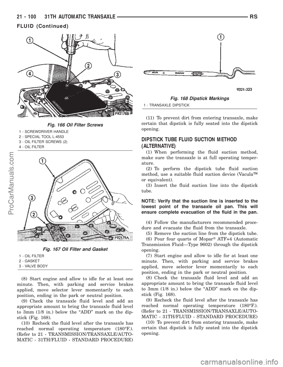
(9) Check the transaxle fluid level and add an
appropriate amount to bring the transaxle fluid level
to 3mm (1/8 in.) below the ªADDº mark on the dip-
stick (Fig. 168).
(10) Recheck the fluid level after the transaxle has
reached normal operating temperature (180ÉF.).
(Refer to 21 - TRANSMISSION/TRANSAXLE/AUTO-
MATIC - 31TH/FLUID - STANDARD PROCEDURE)(11) To prevent dirt from entering transaxle, make
certain that dipstick is fully seated into the dipstick
opening.
DIPSTICK TUBE FLUID SUCTION METHOD
(ALTERNATIVE)
(1) When performing the fluid suction method,
make sure the transaxle is at full operating temper-
ature.
(2) To perform the dipstick tube fluid suction
method, use a suitable fluid suction device (VaculaŸ
or equivalent).
(3) Insert the fluid suction line into the dipstick
tube.
NOTE: Verify that the suction line is inserted to the
lowest point of the transaxle oil pan. This will
ensure complete evacuation of the fluid in the pan.
(4) Follow the manufacturers recommended proce-
dure and evacuate the fluid from the transaxle.
(5) Remove the suction line from the dipstick tube.
(6) Pour four quarts of MopartATF+4 (Automatic
Transmission FluidÐType 9602) through the dipstick
opening.
(7) Start engine and allow to idle for at least one
minute. Then, with parking and service brakes
applied, move selector lever momentarily to each
position, ending in the park or neutral position.
(8) Check the transaxle fluid level and add an
appropriate amount to bring the transaxle fluid level
to 3mm (1/8 in.) below the ªADDº mark on the dip-
stick (Fig. 168).
(9) Recheck the fluid level after the transaxle has
reached normal operating temperature (180ÉF.).
(Refer to 21 - TRANSMISSION/TRANSAXLE/AUTO-
MATIC - 31TH/FLUID - STANDARD PROCEDURE)
(10) To prevent dirt from entering transaxle, make
certain that dipstick is fully seated into the dipstick
opening.
Fig. 166 Oil Filter Screws
1 - SCREWDRIVER HANDLE
2 - SPECIAL TOOL L-4553
3 - OIL FILTER SCREWS (2)
4 - OIL FILTER
Fig. 167 Oil Filter and Gasket
1 - OIL FILTER
2 - GASKET
3 - VALVE BODY
Fig. 168 Dipstick Markings
1 - TRANSAXLE DIPSTICK
21 - 100 31TH AUTOMATIC TRANSAXLERS
FLUID (Continued)
ProCarManuals.com