2002 CHRYSLER VOYAGER body code
[x] Cancel search: body codePage 1988 of 2399
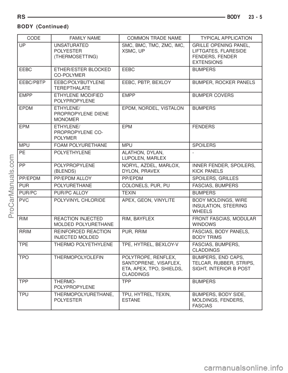
CODE FAMILY NAME COMMON TRADE NAME TYPICAL APPLICATION
UP UNSATURATED
POLYESTER
(THERMOSETTING)SMC, BMC, TMC, ZMC, IMC,
XSMC, UPGRILLE OPENING PANEL,
LIFTGATES, FLARESIDE
FENDERS, FENDER
EXTENSIONS
EEBC ETHER/ESTER BLOCKED
CO-POLYMEREEBC BUMPERS
EEBC/PBTP EEBC/POLYBUTYLENE
TEREPTHALATEEEBC, PBTP, BEXLOY BUMPER, ROCKER PANELS
EMPP ETHYLENE MODIFIED
POLYPROPYLENEEMPP BUMPER COVERS
EPDM ETHYLENE/
PROPROPYLENE DIENE
MONOMEREPDM, NORDEL, VISTALON BUMPERS
EPM ETHYLENE/
PROPROPYLENE CO-
POLYMEREPM FENDERS
MPU FOAM POLYURETHANE MPU SPOILERS
PE POLYETHYLENE ALATHON, DYLAN,
LUPOLEN, MARLEX-
PP POLYPROPYLENE
(BLENDS)NORYL, AZDEL, MARLOX,
DYLON, PRAVEXINNER FENDER, SPOILERS,
KICK PANELS
PP/EPDM PP/EPDM ALLOY PP/EPDM SPOILERS, GRILLES
PUR POLYURETHANE COLONELS, PUR, PU FASCIAS, BUMPERS
PUR/PC PUR/PC ALLOY TEXIN BUMPERS
PVC POLYVINYL CHLORIDE APEX, GEON, VINYLITE BODY MOLDINGS, WIRE
INSULATION, STEERING
WHEELS
RIM REACTION INJECTED
MOLDED POLYURETHANERIM, BAYFLEX FRONT FASCIAS, MODULAR
WINDOWS
RRIM REINFORCED REACTION
INJECTED MOLDEDPUR, RRIM FASCIAS, BODY PANELS,
BODY TRIMS
TPE THERMO POLYETHYLENE TPE, HYTREL, BEXLOY-V FASCIAS, BUMPERS,
CLADDINGS
TPO THERMOPOLYOLEFIN POLYTROPE, RENFLEX,
SANTOPRENE, VISAFLEX,
ETA, APEX, TPO, SHIELDS,
CLADDINGSBUMPERS, END CAPS,
TELCAR, RUBBER, STRIPS,
SIGHT, INTERIOR B POST
TPP THERMO-
POLYPROPYLENETPP BUMPERS
TPU THERMOPOLYURETHANE,
POLYESTERTPU, HYTREL, TEXIN,
ESTANEBUMPERS, BODY SIDE,
MOLDINGS, FENDERS,
FASCIAS
RSBODY23-5
BODY (Continued)
ProCarManuals.com
Page 2064 of 2399
(5) Engage interlock tabs at lower B-pillar and
quarter trim panel.
SUN VISOR
REMOVAL
All vehicles with driver and passenger side air
bags must have a colored coded five Bullet point air
bag warning label applied to the sun visor, verify
label availability and ensure the label is installed.
(1) Disengage sun visor from center support.
(2) Remove screws attaching sun visor to roof
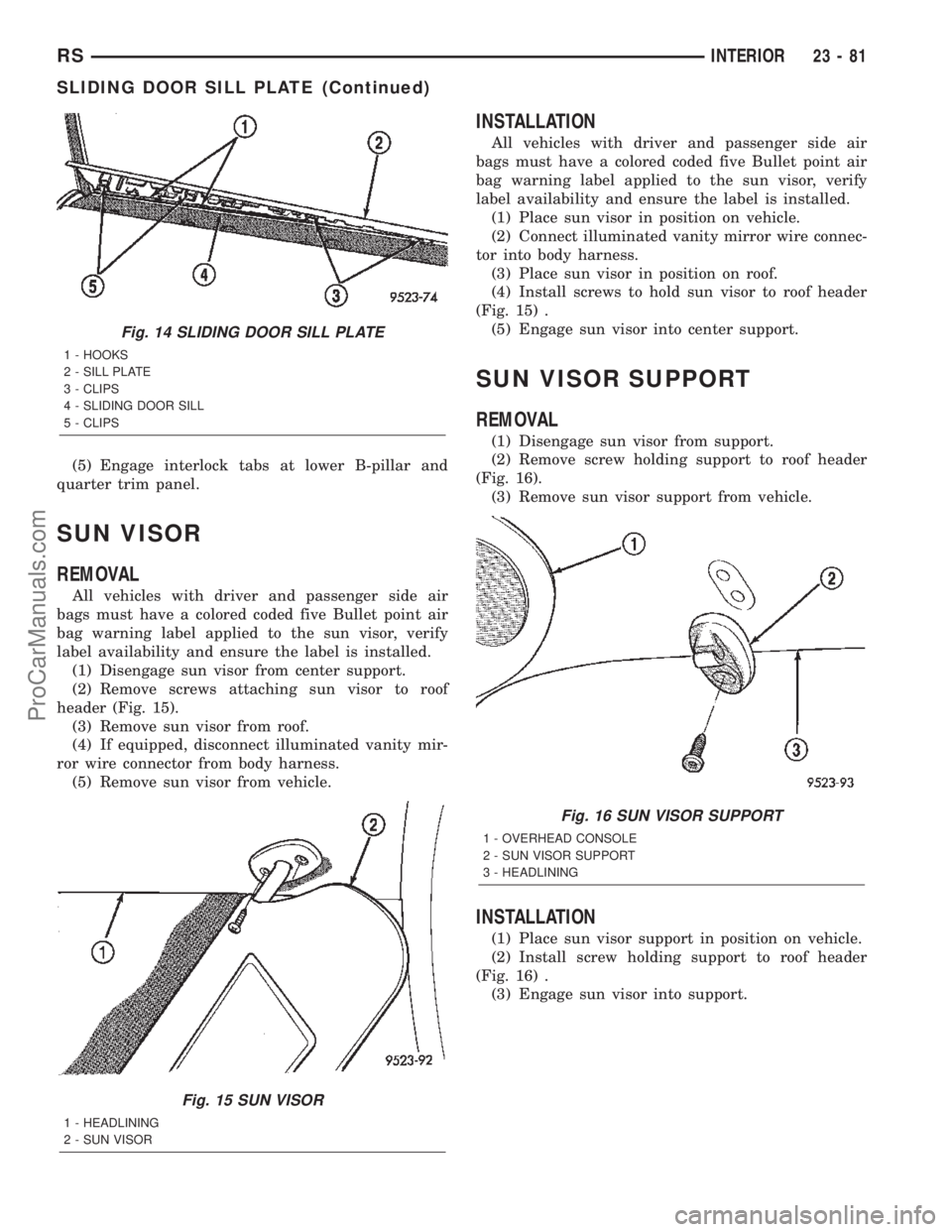
header (Fig. 15).
(3) Remove sun visor from roof.
(4) If equipped, disconnect illuminated vanity mir-
ror wire connector from body harness.
(5) Remove sun visor from vehicle.
INSTALLATION
All vehicles with driver and passenger side air
bags must have a colored coded five Bullet point air
bag warning label applied to the sun visor, verify
label availability and ensure the label is installed.
(1) Place sun visor in position on vehicle.
(2) Connect illuminated vanity mirror wire connec-
tor into body harness.
(3) Place sun visor in position on roof.
(4) Install screws to hold sun visor to roof header
(Fig. 15) .
(5) Engage sun visor into center support.
SUN VISOR SUPPORT
REMOVAL
(1) Disengage sun visor from support.
(2) Remove screw holding support to roof header
(Fig. 16).
(3) Remove sun visor support from vehicle.
INSTALLATION
(1) Place sun visor support in position on vehicle.
(2) Install screw holding support to roof header
(Fig. 16) .
(3) Engage sun visor into support.
Fig. 14 SLIDING DOOR SILL PLATE
1 - HOOKS
2 - SILL PLATE
3 - CLIPS
4 - SLIDING DOOR SILL
5 - CLIPS
Fig. 15 SUN VISOR
1 - HEADLINING
2 - SUN VISOR
Fig. 16 SUN VISOR SUPPORT
1 - OVERHEAD CONSOLE
2 - SUN VISOR SUPPORT
3 - HEADLINING
RSINTERIOR23-81
SLIDING DOOR SILL PLATE (Continued)
ProCarManuals.com
Page 2067 of 2399

PAINT CODE
DESCRIPTION
Exterior vehicle body colors are identified on the
Body Code plate. (Refer to VEHICLE DATA/VEHI-
CLE INFORMATION/BODY CODE PLATE -
DESCRIPTION). The paint code is also identified on
the Vehicle Safety Certification Label which is
located on the drivers door shut face. The first digit
of the paint code listed on the vehicle indicates the
sequence of application, i.e.: P = primary coat, Q =
secondary coat. The codes listed in the Color Code
Chart are used for manufacturing purposes.
PAINTED TOUCH-UP
DESCRIPTION
When a painted metal surface has been scratched
or chipped, it should be touched up as soon as possi-
ble to avoid corrosion. For best results, use Mopart
Scratch Filler/Primer, Touch Up Paints and Clear Top
Coat. (Refer to VEHICLE DATA/VEHICLE INFOR-
MATION/BODY CODE PLATE - DESCRIPTION).
WARNING: USE A OSHA APPROVED BREATHING
MASK WHEN SPRAYING PAINT OR SOLVENTS IN A
CONFINED AREA. PERSONAL INJURY CAN
RESULT.
TOUCH UP PROCEDURE
(1) Scrape loose paint and corrosion from inside
scratch or chip.
(2) Clean affected area with MopartTar/Road Oil
Remover, and allow to dry.
(3) Fill the inside of the scratch or chip with a coat
of filler/primer. Do not overlap primer onto good sur-
face finish. The applicator brush should be wetenough to puddle-fill the defect without running. Do
not stroke brush applicator on body surface. Allow
the filler/primer to dry hard.
(4) Cover the filler/primer with color touch up
paint. Do not overlap touch up color onto the original
color coat around the scratch or chip. Butt the new
color to the original color, if possible. Do not stroke
applicator brush on body surface. Allow touch up
paint to dry hard.
(5) On vehicles without clearcoat, the touch up
color can be lightly finesse sanded (1500 grit) and
polished with rubbing compound.
(6) On vehicles with clearcoat, apply clear top coat
to touch up paint with the same technique as
described in Step 4. Allow clear top coat to dry hard.
If desired, Step 5 can be performed on clear top coat.
WARNING: AVOID PROLONGED SKIN CONTACT
WITH PETROLEUM OR ALCOHOL ± BASED CLEAN-
ING SOLVENTS. PERSONAL INJURY CAN RESULT.
FINESSE SANDING/BUFFING &
POLISHING
DESCRIPTION
Minor acid etching, orange peel, or smudging in
clearcoat or single-stage finishes can be reduced with
light finesse sanding, hand buffing, and polishing.If
the finish has been finesse sanded in the past,
it cannot be repeated. Finesse sanding opera-
tion should be performed by a trained automo-
tive paint technician.
CAUTION: Do not remove clearcoat finish, if
equipped. Basecoat paint must retain clearcoat for
durability.
23 - 84 PAINTRS
ProCarManuals.com
Page 2252 of 2399
(3) The calibration procedure should take less than
two minutes to complete for the manual heater-A/C
control, and less than twenty seconds for the ATC
heater-A/C control. When the LEDs or graphics stop
flashing, the calibration procedure is complete.
(4) If the LEDs or graphics continue to flash
beyond the normal three minute (manual) or twenty
second (ATC) calibration time, it indicates that the
heater-A/C control has detected a failure and a Diag-
nostic Trouble Code (DTC) has been set. Use a
DRBIIItscan tool to perform further diagnosis. Refer
to the appropriate diagnostic information. The LEDs
or graphics will continue to flash even after the igni-
tion switch is cycled Off and On, until a successful
calibration is completed or until the vehicle has been
driven about 13 kilometers (8 miles).
REMOVAL
WARNING: ON VEHICLES EQUIPPED WITH AIR-
BAGS, DISABLE THE AIRBAG SYSTEM BEFORE
ATTEMPTING ANY STEERING WHEEL, STEERING
COLUMN, OR INSTRUMENT PANEL COMPONENT
DIAGNOSIS OR SERVICE. DISCONNECT AND ISO-
LATE THE BATTERY NEGATIVE (GROUND) CABLE,
THEN WAIT TWO MINUTES FOR THE AIRBAG SYS-
TEM CAPACITOR TO DISCHARGE BEFORE PER-
FORMING FURTHER DIAGNOSIS OR SERVICE. THIS
IS THE ONLY SURE WAY TO DISABLE THE AIRBAG
SYSTEM. FAILURE TO TAKE THE PROPER PRE-
CAUTIONS COULD RESULT IN ACCIDENTAL AIR-
BAG DEPLOYMENT AND POSSIBLE PERSONAL
INJURY.
(1) Disconnect and isolate the battery negative
cable.
(2) Remove the center bezel from the instrument
panel. (Refer to 23 - BODY/INSTRUMENT PANEL/
INSTRUMENT PANEL CENTER BEZEL - REMOV-
AL).
(3) Place the instrument panel center bezel unit
face down on a suitable work surface. Take the
proper precautions to protect the center bezel from
cosmetic damage.
(4) If the vehicle is equipped with the optional
Automatic Temperature Control (ATC) system, dis-
connect the infrared sensor jumper harness connector
from the receptacle on the back of the heater-A/C
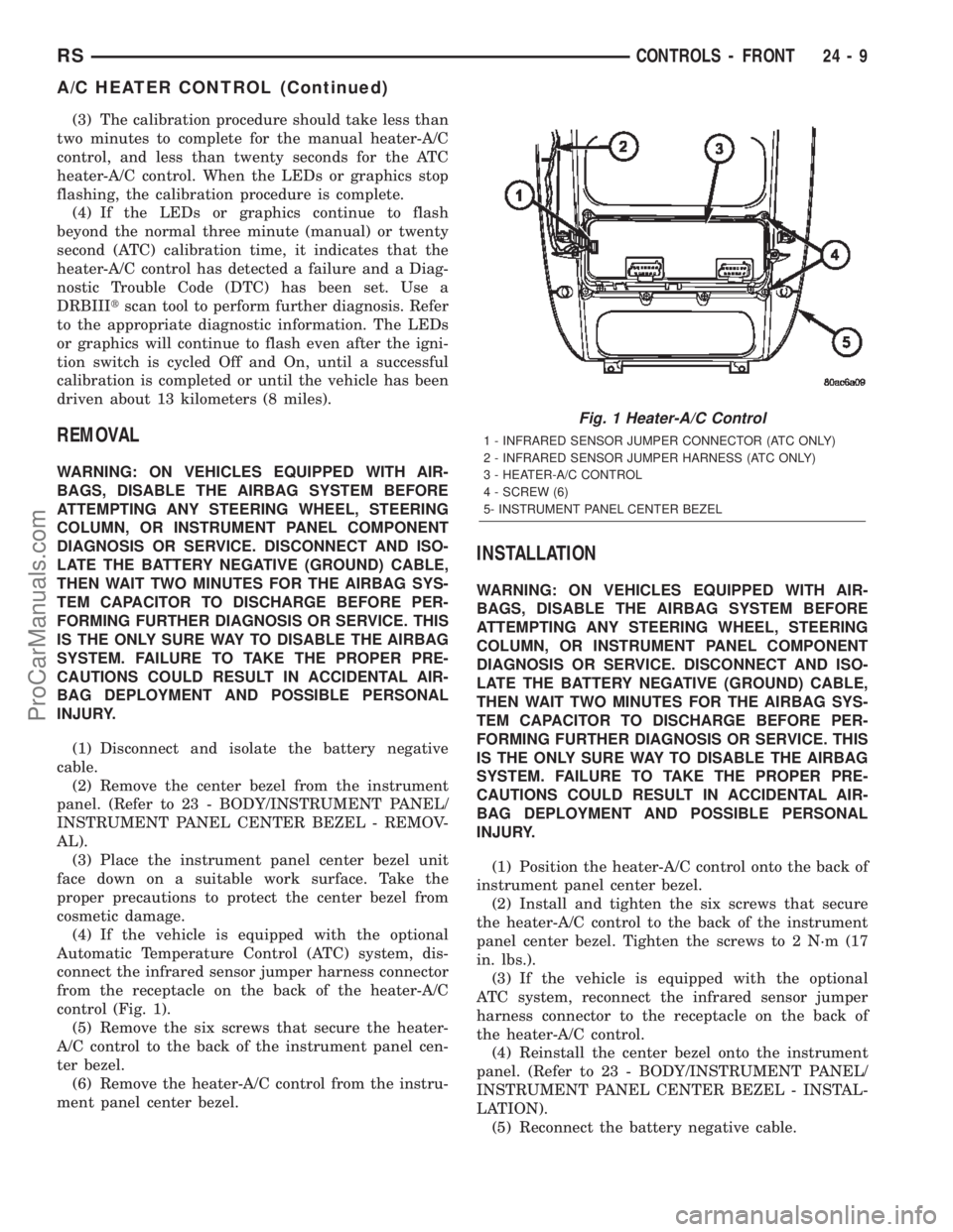
control (Fig. 1).
(5) Remove the six screws that secure the heater-
A/C control to the back of the instrument panel cen-
ter bezel.
(6) Remove the heater-A/C control from the instru-
ment panel center bezel.
INSTALLATION
WARNING: ON VEHICLES EQUIPPED WITH AIR-
BAGS, DISABLE THE AIRBAG SYSTEM BEFORE
ATTEMPTING ANY STEERING WHEEL, STEERING
COLUMN, OR INSTRUMENT PANEL COMPONENT
DIAGNOSIS OR SERVICE. DISCONNECT AND ISO-
LATE THE BATTERY NEGATIVE (GROUND) CABLE,
THEN WAIT TWO MINUTES FOR THE AIRBAG SYS-
TEM CAPACITOR TO DISCHARGE BEFORE PER-
FORMING FURTHER DIAGNOSIS OR SERVICE. THIS
IS THE ONLY SURE WAY TO DISABLE THE AIRBAG
SYSTEM. FAILURE TO TAKE THE PROPER PRE-
CAUTIONS COULD RESULT IN ACCIDENTAL AIR-
BAG DEPLOYMENT AND POSSIBLE PERSONAL
INJURY.
(1) Position the heater-A/C control onto the back of
instrument panel center bezel.
(2) Install and tighten the six screws that secure
the heater-A/C control to the back of the instrument
panel center bezel. Tighten the screws to 2 N´m (17
in. lbs.).
(3) If the vehicle is equipped with the optional
ATC system, reconnect the infrared sensor jumper
harness connector to the receptacle on the back of
the heater-A/C control.
(4) Reinstall the center bezel onto the instrument
panel. (Refer to 23 - BODY/INSTRUMENT PANEL/
INSTRUMENT PANEL CENTER BEZEL - INSTAL-
LATION).
(5) Reconnect the battery negative cable.
Fig. 1 Heater-A/C Control
1 - INFRARED SENSOR JUMPER CONNECTOR (ATC ONLY)
2 - INFRARED SENSOR JUMPER HARNESS (ATC ONLY)
3 - HEATER-A/C CONTROL
4 - SCREW (6)
5- INSTRUMENT PANEL CENTER BEZEL
RSCONTROLS - FRONT24-9
A/C HEATER CONTROL (Continued)
ProCarManuals.com
Page 2268 of 2399
it to the linkage that drives the mode door. The mode
door actuator does not require mechanical indexing
to the mode door linkage, as it is electronically cali-
brated by the heater-A/C control module. The mode
door actuator cannot be adjusted or repaired and, if
damaged or faulty, it must be replaced.
OPERATION
The mode door actuator is connected to the heater-
A/C control module through the vehicle electrical sys-
tem by a dedicated two-wire take out and connector
of the HVAC wire harness. The mode door actuator
can move the mode door in two directions. When the
heater-A/C control module pulls the voltage on one
side of the motor connection high and the other con-
nection low, the mode door will move in one direction.
When the module reverses the polarity of the voltage
to the motor, the mode door moves in the opposite
direction. When the module makes the voltage to
both connections high or both connections low, the
mode door stops and will not move. These same
motor connections also provide a feedback signal to
the heater-A/C control module. This feedback signal
allows the module to monitor the operation and rela-
tive position of the mode door actuator and the mode
door. The heater-A/C control module learns the mode
door stop positions during the calibration procedure
and will store a Diagnostic Trouble Code (DTC) for
any problems it detects in the mode door actuator
circuits. The mode door actuator can be diagnosed
using a DRBIIItscan tool. Refer to the appropriate
diagnostic information.
REMOVAL
WARNING: ON VEHICLES EQUIPPED WITH AIR-
BAGS, DISABLE THE AIRBAG SYSTEM BEFORE
ATTEMPTING ANY STEERING WHEEL, STEERING
COLUMN, OR INSTRUMENT PANEL COMPONENT
DIAGNOSIS OR SERVICE. DISCONNECT AND ISO-
LATE THE BATTERY NEGATIVE (GROUND) CABLE,
THEN WAIT TWO MINUTES FOR THE AIRBAG SYS-
TEM CAPACITOR TO DISCHARGE BEFORE PER-
FORMING FURTHER DIAGNOSIS OR SERVICE. THIS
IS THE ONLY SURE WAY TO DISABLE THE AIRBAG
SYSTEM. FAILURE TO TAKE THE PROPER PRE-
CAUTIONS COULD RESULT IN ACCIDENTAL AIR-
BAG DEPLOYMENT AND POSSIBLE PERSONAL
INJURY.
(1) Disconnect and isolate the battery negative
cable.
(2) Remove the silencer from beneath the driver
side end of the instrument panel. (Refer to 23 -
BODY/INSTRUMENT PANEL/INSTRUMENT
PANEL SILENCER - REMOVAL).(3) Disconnect the HVAC wire harness connector
for the mode door actuator from the actuator connec-
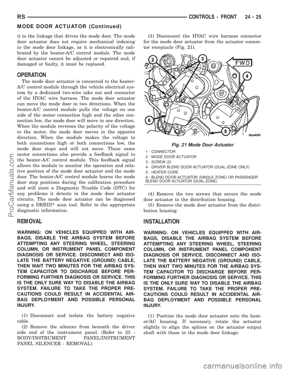
tor receptacle (Fig. 21).
(4) Remove the two screws that secure the mode
door actuator to the distribution housing.
(5) Remove the mode door actuator from the distri-
bution housing.
INSTALLATION
WARNING: ON VEHICLES EQUIPPED WITH AIR-
BAGS, DISABLE THE AIRBAG SYSTEM BEFORE
ATTEMPTING ANY STEERING WHEEL, STEERING
COLUMN, OR INSTRUMENT PANEL COMPONENT
DIAGNOSIS OR SERVICE. DISCONNECT AND ISO-
LATE THE BATTERY NEGATIVE (GROUND) CABLE,
THEN WAIT TWO MINUTES FOR THE AIRBAG SYS-
TEM CAPACITOR TO DISCHARGE BEFORE PER-
FORMING FURTHER DIAGNOSIS OR SERVICE. THIS
IS THE ONLY SURE WAY TO DISABLE THE AIRBAG
SYSTEM. FAILURE TO TAKE THE PROPER PRE-
CAUTIONS COULD RESULT IN ACCIDENTAL AIR-
BAG DEPLOYMENT AND POSSIBLE PERSONAL
INJURY.
(1) Position the mode door actuator onto the heat-
er/AC housing. If necessary, rotate the actuator
slightly to align the splines on the actuator output
shaft with those in the mode door linkage.
Fig. 21 Mode Door Actuator
1 - CONNECTOR
2 - MODE DOOR ACTUATOR
3 - SCREW (2)
4 - DRIVER BLEND DOOR ACTUATOR (DUAL-ZONE ONLY)
5 - HEATER CORE
6 - BLEND DOOR ACTUATOR (SINGLE ZONE) OR PASSENGER
BLEND DOOR ACTUATOR (DUAL-ZONE)
RSCONTROLS - FRONT24-25
MODE DOOR ACTUATOR (Continued)
ProCarManuals.com
Page 2274 of 2399
high and the other connection low, the blend air door
will move in one direction. When the module reverses
the polarity of the voltage to the motor, the blend air
door moves in the opposite direction. When the mod-
ule makes the voltage to both connections high or
both connections low, the blend air door stops and
will not move. These same motor connections also
provide a feedback signal to the front heater-A/C con-
trol module. This feedback signal allows the module
to monitor the operation and relative positions of the
blend door actuator and the blend air door. The front
heater-A/C control module learns the blend air door
stop positions during the calibration procedure and
will store a Diagnostic Trouble Code (DTC) for any
problems it detects in the blend door actuator cir-
cuits. A DTC can be retrieved and the blend door
actuator can be diagnosed using a DRBIIItscan tool.
Refer to the appropriate diagnostic information.
REMOVAL
(1) Disconnect and isolate the battery negative
cable.
(2) Remove the right quarter trim panel and right
D-pillar trim panel from the quarter inner panel.
(Refer to 23 - BODY/INTERIOR/QUARTER TRIM
PANEL - REMOVAL).
(3) Remove the two screws that secure the top of
the quarter trim panel attaching bracket to the quar-
ter inner panel.
(4) Remove the screw that secures the back of the
rear heater-A/C unit housing to the right D-pillar.
(5) Remove the screw that secures the front of the
rear heater-A/C unit housing to the right quarter
inner panel.
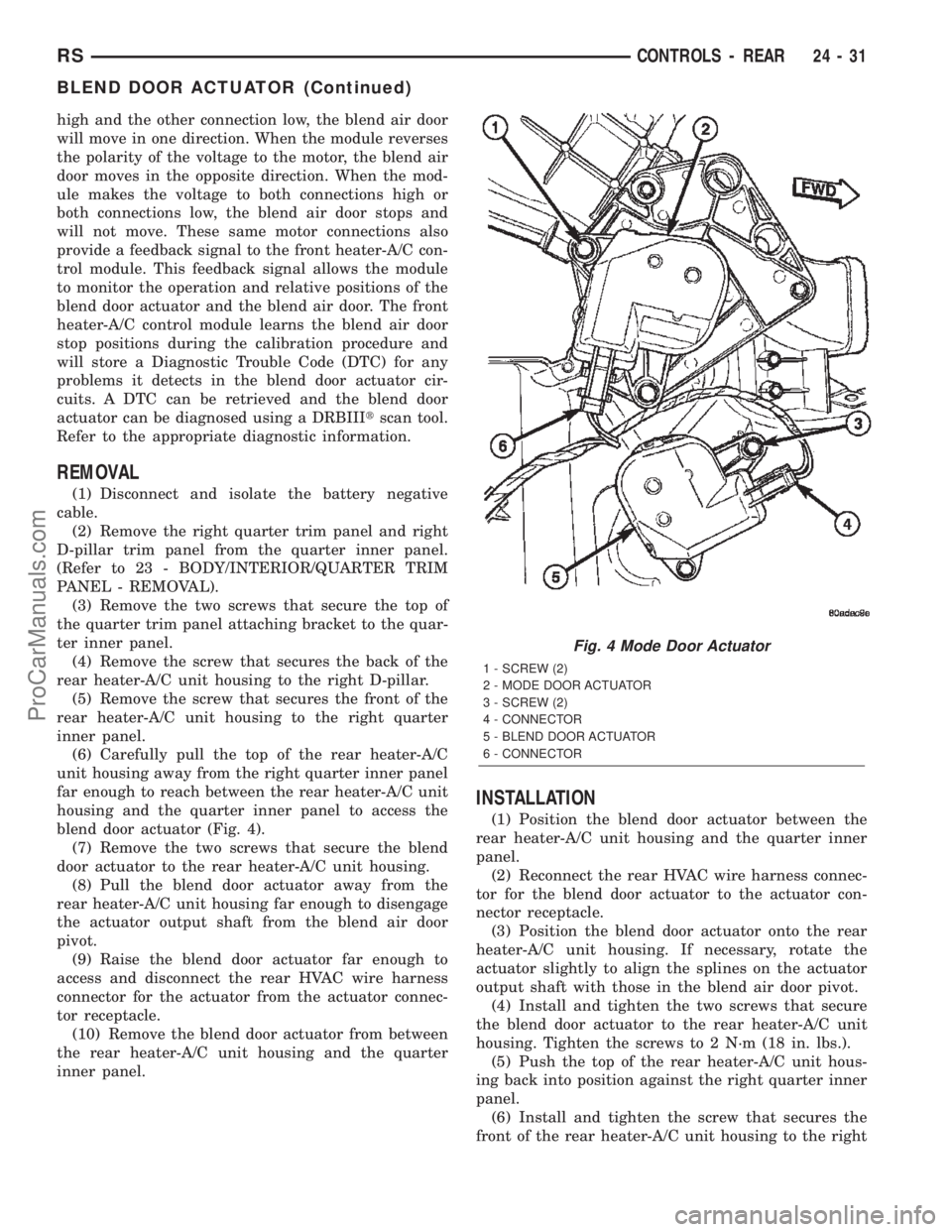
(6) Carefully pull the top of the rear heater-A/C
unit housing away from the right quarter inner panel
far enough to reach between the rear heater-A/C unit
housing and the quarter inner panel to access the
blend door actuator (Fig. 4).
(7) Remove the two screws that secure the blend
door actuator to the rear heater-A/C unit housing.
(8) Pull the blend door actuator away from the
rear heater-A/C unit housing far enough to disengage
the actuator output shaft from the blend air door
pivot.
(9) Raise the blend door actuator far enough to
access and disconnect the rear HVAC wire harness
connector for the actuator from the actuator connec-
tor receptacle.
(10) Remove the blend door actuator from between
the rear heater-A/C unit housing and the quarter
inner panel.
INSTALLATION
(1) Position the blend door actuator between the
rear heater-A/C unit housing and the quarter inner
panel.
(2) Reconnect the rear HVAC wire harness connec-
tor for the blend door actuator to the actuator con-
nector receptacle.
(3) Position the blend door actuator onto the rear
heater-A/C unit housing. If necessary, rotate the
actuator slightly to align the splines on the actuator
output shaft with those in the blend air door pivot.
(4) Install and tighten the two screws that secure
the blend door actuator to the rear heater-A/C unit
housing. Tighten the screws to 2 N´m (18 in. lbs.).
(5) Push the top of the rear heater-A/C unit hous-
ing back into position against the right quarter inner
panel.
(6) Install and tighten the screw that secures the
front of the rear heater-A/C unit housing to the right
Fig. 4 Mode Door Actuator
1 - SCREW (2)
2 - MODE DOOR ACTUATOR
3 - SCREW (2)
4 - CONNECTOR
5 - BLEND DOOR ACTUATOR
6 - CONNECTOR
RSCONTROLS - REAR24-31
BLEND DOOR ACTUATOR (Continued)
ProCarManuals.com
Page 2279 of 2399
INFRARED TEMPERATURE
SENSOR
DESCRIPTION
The rear infrared temperature sensor consists of
an infrared transducer that is concealed behind the
lens of the rear heater-A/C control in the headliner.
This sensor is used only on models equipped with the
optional Automatic Temperature Control (ATC) heat-
ing and air conditioning system. The rear infrared
temperature sensor is integral to the rear heater-A/C
control. The infrared sensor cannot be adjusted or
repaired and, if faulty or damaged, the rear heater-
A/C control unit must be replaced.
OPERATION
The rear infrared temperature sensor provides an
independent measurement input to the Automatic
Temperature Control (ATC) heater-A/C control mod-
ule that indicates the surface temperature of the rear
seat occupants. By using a surface temperature mea-
surement, rather than an air temperature measure-
ment, the ATC system is able to adjust itself to the
comfort level as perceived by the occupant. This
allows the system to detect and compensate for other
ambient conditions affecting comfort levels, such as
solar heat gain or evaporative heat loss. The ATC
system logic responds to the infrared sensor input by
calculating and adjusting the air flow temperature
and air flow rate needed to properly obtain and
maintain the selected comfort level temperatures for
the rear seat occupants. The ATC heater-A/C control
module continually monitors the infrared sensor cir-
cuit, and will store a Diagnostic Trouble Code (DTC)
for any problem it detects. This DTC information can
be retrieved and the infrared temperature sensor
diagnosed using a DRBIIItscan tool. Refer to the
appropriate diagnostic information.
MODE DOOR ACTUATOR
REMOVAL
(1) Disconnect and isolate the battery negative
cable.
(2) Remove the right quarter trim panel and right
D-pillar trim panel from the quarter inner panel.
(Refer to 23 - BODY/INTERIOR/QUARTER TRIM
PANEL - REMOVAL).
(3) Remove the two screws that secure the top of
the quarter trim panel attaching bracket to the quar-
ter inner panel.
(4) Remove the screw that secures the back of the
rear heater-A/C unit housing to the right D-pillar.(5) Remove the screw that secures the front of the
rear heater-A/C unit housing to the right quarter
inner panel.
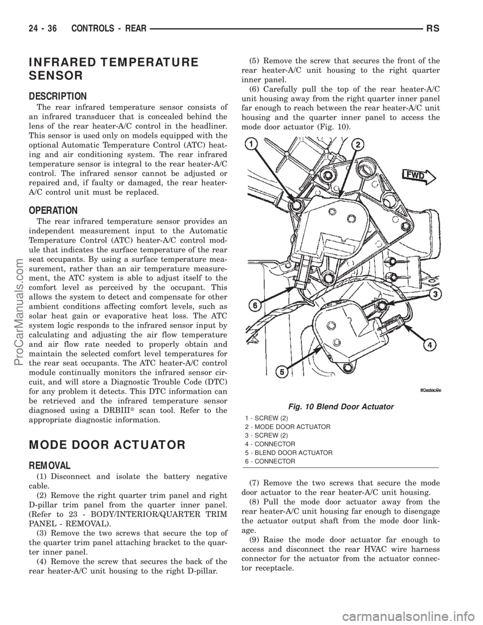
(6) Carefully pull the top of the rear heater-A/C
unit housing away from the right quarter inner panel
far enough to reach between the rear heater-A/C unit
housing and the quarter inner panel to access the
mode door actuator (Fig. 10).
(7) Remove the two screws that secure the mode
door actuator to the rear heater-A/C unit housing.
(8) Pull the mode door actuator away from the
rear heater-A/C unit housing far enough to disengage
the actuator output shaft from the mode door link-
age.
(9) Raise the mode door actuator far enough to
access and disconnect the rear HVAC wire harness
connector for the actuator from the actuator connec-
tor receptacle.
Fig. 10 Blend Door Actuator
1 - SCREW (2)
2 - MODE DOOR ACTUATOR
3 - SCREW (2)
4 - CONNECTOR
5 - BLEND DOOR ACTUATOR
6 - CONNECTOR
24 - 36 CONTROLS - REARRS
ProCarManuals.com
Page 2365 of 2399
FUEL INJECTOR MECHANICAL MALFUNCTIONS
The PCM cannot determine if a fuel injector is
clogged, the needle is sticking or if the wrong injector
is installed. However, these could result in a rich or
lean condition causing the PCM to store a diagnostic
trouble code for either misfire, an oxygen sensor, or
the fuel system.
EXCESSIVE OIL CONSUMPTION
Although the PCM monitors engine exhaust oxygen
content when the system is in closed loop, it cannot
determine excessive oil consumption.
THROTTLE BODY AIR FLOW
The PCM cannot detect a clogged or restricted air
cleaner inlet or filter element.
VACUUM ASSIST
The PCM cannot detect leaks or restrictions in the
vacuum circuits of vacuum assisted engine control
system devices. However, these could cause the PCM
to store a MAP sensor diagnostic trouble code and
cause a high idle condition.
PCM SYSTEM GROUND
The PCM cannot determine a poor system ground.
However, one or more diagnostic trouble codes may
be generated as a result of this condition. The mod-
ule should be mounted to the body at all times, also
during diagnostic.
PCM CONNECTOR ENGAGEMENT
The PCM may not be able to determine spread or
damaged connector pins. However, it might store
diagnostic trouble codes as a result of spread connec-
tor pins.
DESCRIPTION - MONITORED SYSTEMS
There are new electronic circuit monitors that
check fuel, emission, engine and ignition perfor-
mance. These monitors use information from various
sensor circuits to indicate the overall operation of the
fuel, engine, ignition and emission systems and thus
the emissions performance of the vehicle.
The fuel, engine, ignition and emission systems
monitors do not indicate a specific component prob-
lem. They do indicate that there is an implied prob-
lem within one of the systems and that a specific
problem must be diagnosed.
If any of these monitors detect a problem affecting
vehicle emissions, the Malfunction Indicator (Check
Engine) Lamp will be illuminated. These monitors
generate Diagnostic Trouble Codes that can be dis-
played with the a DRBIIItscan tool.
The following is a list of the system monitors:
²EGR Monitor (if equipped)²Misfire Monitor
²Fuel System Monitor
²Oxygen Sensor Monitor
²Oxygen Sensor Heater Monitor
²Catalyst Monitor
²Evaporative System Leak Detection Monitor (if
equipped)
Following is a description of each system monitor,
and its DTC.
Refer to the appropriate Powertrain Diagnos-
tics Procedures manual for diagnostic proce-
dures.
OXYGEN SENSOR (O2S) MONITOR
Effective control of exhaust emissions is achieved
by an oxygen feedback system. The most important
element of the feedback system is the O2S. The O2S
is located in the exhaust path. Once it reaches oper-
ating temperatures of 300É to 350ÉC (572É to 662ÉF),
the sensor generates a voltage that is inversely pro-
portional to the amount of oxygen in the exhaust.
The information obtained by the sensor is used to
calculate the fuel injector pulse width. The PCM is
programmed to maintain the optimum air/fuel ratio.
At this mixture ratio, the catalyst works best to
remove hydrocarbons (HC), carbon monoxide (CO)
and nitrous oxide (NOx) from the exhaust.
The O2S is also the main sensing element for the
EGR (if equipped), Catalyst and Fuel Monitors.
The O2S may fail in any or all of the following
manners:
²Slow response rate
²Reduced output voltage
²Dynamic shift
²Shorted or open circuits
Response rate is the time required for the sensor to
switch from lean to rich once it is exposed to a richer
than optimum A/F mixture or vice versa. As the sen-
sor starts malfunctioning, it could take longer to
detect the changes in the oxygen content of the
exhaust gas.
The output voltage of the O2S ranges from 0 to 1
volt. A good sensor can easily generate any output
voltage in this range as it is exposed to different con-
centrations of oxygen. To detect a shift in the A/F
mixture (lean or rich), the output voltage has to
change beyond a threshold value. A malfunctioning
sensor could have difficulty changing beyond the
threshold value.
OXYGEN SENSOR HEATER MONITOR
If there is an oxygen sensor (O2S) DTC as well as
a O2S heater DTC, the O2S fault MUST be repaired
first. After the O2S fault is repaired, verify that the
heater circuit is operating correctly.
25 - 6 EMISSIONS CONTROLRS
EMISSIONS CONTROL (Continued)
ProCarManuals.com