2002 CHRYSLER VOYAGER body code
[x] Cancel search: body codePage 497 of 2399

CONDITION POSSIBLE CAUSES CORRECTION
ERRATIC DISPLAY 1. INTERNAL CLUSTER
FAILURE.1. PERFORM CLUSTER SELF-DIAGNOSTIC TEST
AND CHECK FOR FAULT CODES.
²IF ODOMETER PASSES THE SEGMENT TEST,
FAILURE MAY NOT BE IN THE CLUSTER. LOOK
FOR ANOTHER POSSIBLE CAUSE OF FAILURE.
2. VERIFY GOOD POWER AND GROUND
CONNECTIONS. IF CONNECTIONS ARE GOOD AND
NO OTHER PROBLEMS ARE FOUND, REPLACE
CLUSTER ASSEMBLY.
2. BAD PCI BUS
MESSAGE FROM THE
BCM.2. USE A DRB IIITSCAN TOOL TO CHECK THE
BCM. REFER TO THE PROPER BODY DIAGNOSTIC
PROCEDURES MANUAL TO PROPERLY DIAGNOSE
AND REPAIR.
ODOMETER WON'T GO
INTO TRIP MODE.TRIP SWITCH DOESN'T
WORK.IF CLUSTER WILL NOT GO INTO SELF DIAGNOSTIC
MODE AND CANNOT TOGGLE BETWEEN
ODOMETER AND TRIP ODOMETER, REPLACE
CLUSTER.
TRIP ODOMETER WON'T
RESET.RESET SWITCH
DOESN'T WORK.IF CLUSTER WILL NOT GO INTO SELF DIAGNOSTIC
MODE AND TRIP ODOMETER WILL NOT RESET,
REPLACE CLUSTER.
ELECTRONIC GEAR INDICATOR DISPLAY DIAGNOSIS
CONDITION POSSIBLE CAUSES CORRECTION
NO DISPLAY. 1. INTERNAL CLUSTER
FAILURE.1. PERFORM CLUSTER SELF-DIAGNOSTIC TEST
AND CHECK FOR FAULT CODES.
²IF PRND3L (PRND1234 IF AUTOSTICK
EQUIPPED) PASSES THE SEGMENT CHECK, THEN
FAILURE MAY NOT BE IN THE CLUSTER. LOOK
FOR ANOTHER POSSIBLE CAUSE OF FAILURE. IF
IT FAILS, REPLACE CLUSTER ASSEMBLY.
ERRATIC DISPLAY. 1. INTERNAL CLUSTER
FAILURE.1. PERFORM CLUSTER SELF-DIAGNOSTIC TEST
AND CHECK FOR FAULT CODES.
²IF PRND3L (PRND1234 IF AUTOSTICK
EQUIPPED) PASSES THE SEGMENT CHECK, THEN
FAILURE MAY NOT BE IN THE CLUSTER. LOOK
FOR ANOTHER POSSIBLE CAUSE OF FAILURE.
2. BAD PCI BUS
MESSAGE FROM THE
TCM.2. USE A DRB IIITSCAN TOOL TO CHECK THE
TCM. REFER TO THE PROPER TRANSMISSION
DIAGNOSTIC PROCEDURES MANUAL TO
PROPERLY DIAGNOSE AND REPAIR.
8J - 10 INSTRUMENT CLUSTERRS
INSTRUMENT CLUSTER (Continued)
ProCarManuals.com
Page 544 of 2399

The power liftgate control module communicates
on the J1850 Programmable Communication Inter-
face (PCI) Bus Circuit. Therefore, the power liftgate
control module can generate and store its own Diag-
nostic Trouble Codes (DTC). The vehicles Body Con-
trol Module (BCM) receives and supplies messages tothe power liftgate control module via the PCI bus cir-
cuit. A diagnostic scan tool, such as the DRB IIItis
used to read and troubleshoot these Diagnostic Trou-
ble Codes (DTC). Refer to the Body Diagnostic Man-
ual for a complete list of diagnostic routines.
For additional information refer to Power Liftgate
Operation. For a complete system wiring schematic
refer to Wiring Diagrams. For system operation
instructions refer to the vehicles owner manual.
Refer to the Body section of the service manual
for additional information on liftgate components
such as the prop rods, hinges, door alignment and
striker alignment.
WARNING: BE CERTAIN TO READ ALL WARNINGS
AND CAUTIONS (NOTED BELOW) IN POWER LIFT-
GATE SYSTEM OPERATION BEFORE ATTEMPTING
ANY SERVICE OF THE POWER LIFTGATE SYSTEM
OR COMPONENTS.
OPERATION
With the push of a power liftgate open/close com-
mand switch (key fob or overhead console mounted) a
signal is sent out on the J1850 PCI Data Bus circuit.
This signal is detected at the body control module
(BCM). The BCM then sends a signal out on the
J1850 PCI Data Bus circuit to the power liftgate
module. The power liftgate module then signals the
power liftgate motor to start an open or close cycle,
depending on what position the liftgate is in open or
closed.
During a liftgate open or close cycle, if the power
liftgate module detects sufficient resistance to liftgate
travel, such as an obstruction in the liftgates path,
the power liftgate control module will immediately
stop the liftgate movement and reverse travel to the
full open or closed position. The ability for the power
liftgate module to detect resistance to liftgate travel
is accomplished by hall effect sensors, drive motor
speed and pinch sensors (tape switches).
The power liftgate control module has the ability to
learn. Anytime the liftgate is opened or closed using
the power liftgate system the module learns from its
cycle. If a replacement power liftgate component is
installed or a liftgate adjustment is made, the mod-
ule will relearn the effort and/or time required to
open or close the door. This learn cycle can be per-
formed with a Diagnostic Scan Tool, such as the DRB
IIItor with a complete cycle of the liftgate, using
any one of the command switches. Refer to Standard
Procedures in this section for detailed instructions.Fig. 2 KEY FOB
1 - Left Sliding Door Switch
2 - Right Sliding Door Switch
3 - Liftgate Switch
Fig. 3 LIFTGATE FUSE LOCATION
RSPOWER LIFTGATE SYSTEM8N-3
POWER LIFTGATE SYSTEM (Continued)
ProCarManuals.com
Page 545 of 2399

The power liftgate system is designed with a num-
ber of system inhibitors. These inhibitors are neces-
sary for safety and / or feasibility of the power
liftgate system. Refer to power liftgate system inhib-
itors noted below:
POWER LIFTGATE SYSTEM INHIBITORS
²The Power Liftgate may not operate in extreme
temperatures. These extreme temperatures will be
approximately -12É F (-24.4É C) on the low side and
143É F (61.6É C) for the high side. A chime/thermister
assembly in the rear light bar assembly monitors the
outside temperature.
²The vehicles transmission must be in park or
neutral for the power liftgate to start a cycle.
²If multiple obstacles are detected during the
same power open or close cycle the liftgate goes into
manual operation.
²If severe Diagnostic Trouble Codes (DTC) are
stored in the power liftgate control module.
POWER LIFTGATE SYSTEM CAUTIONS AND
WARNINGS
WARNING: ALWAYS DISCONNECT THE NEGATIVE
BATTERY CABLE BEFORE ATTEMPTING ANY
POWER LIFTGATE SYSTEM SERVICE.
WARNING: THERE IS A SMALL AREA ON BOTH
SIDES OF THE LOWER POWER LIFTGATE WHICH
ARE NOT PROTECTED BY PINCH SENSORS.
EXTREME CARE MUST BE TAKEN TO PREVENT
OBJECTS FROM ENTERING THIS AREA ONCE THE
LIFTGATE REACHES THE SECONDARY LATCH
CONTACT (APPROXIMATELY 1/2 INCH BEFORE
FULLY CLOSED).
WARNING: NEVER ATTEMPT TO ENTER OR EXIT
THE VEHICLE WITH THE LIFTGATE IN MOTION.
YOU COULD DAMAGE THE POWER LIFTGATE SYS-TEM AND/OR COMPONENTS AND/OR CAUSE PER-
SONAL INJURY.
WARNING: NEVER STICK OBJECTS IN THE POWER
LIFTGATE WHEN CINCHING CLOSED. YOU COULD
DAMAGE THE VEHICLE, POWER LIFTGATE SYS-
TEM COMPONENTS AND/OR CAUSE PERSONAL
INJURY.
DIAGNOSIS AND TESTING - POWER LIFTGATE
SYSTEM
The power opening and closing power liftgate sys-
tem is a complex system containing many compo-
nents and modules. In order to obtain conclusive
testing the Programmable Communications Interface
(J1850) data bus network and all of the electronic
modules that provide inputs to, or receive outputs
from the power liftgate system must be checked.
The power liftgate system was designed to be diag-
nosed with an appropriate diagnostic scan tool, such
as the DRB IIIt. The most reliable, efficient, and
accurate means to diagnose the power liftgate system
requires the use of a DRB IIItscan tool and the
proper Body Diagnostic Procedures manual. The
DRB IIItcan be used to observe various switch sta-
tuses throughout the power liftgate system to help
the technician diagnose a defective switch or compo-
nent. The DRB IIItcan also be used to actuate var-
ious components throughout the power liftgate
system to help the technician diagnose a defective
component.
Before any testing of the power liftgate system is
attempted, the battery should be fully charged, all
built-in power liftgate system inhibitors read and
understood (Refer to power liftgate system operation)
and all wire harness and ground connections
inspected around the affected areas on the vehicle.
Following are quick reference diagnostic tables to
help when diagnosing and testing the power liftgate
system.
8N - 4 POWER LIFTGATE SYSTEMRS
POWER LIFTGATE SYSTEM (Continued)
ProCarManuals.com
Page 546 of 2399
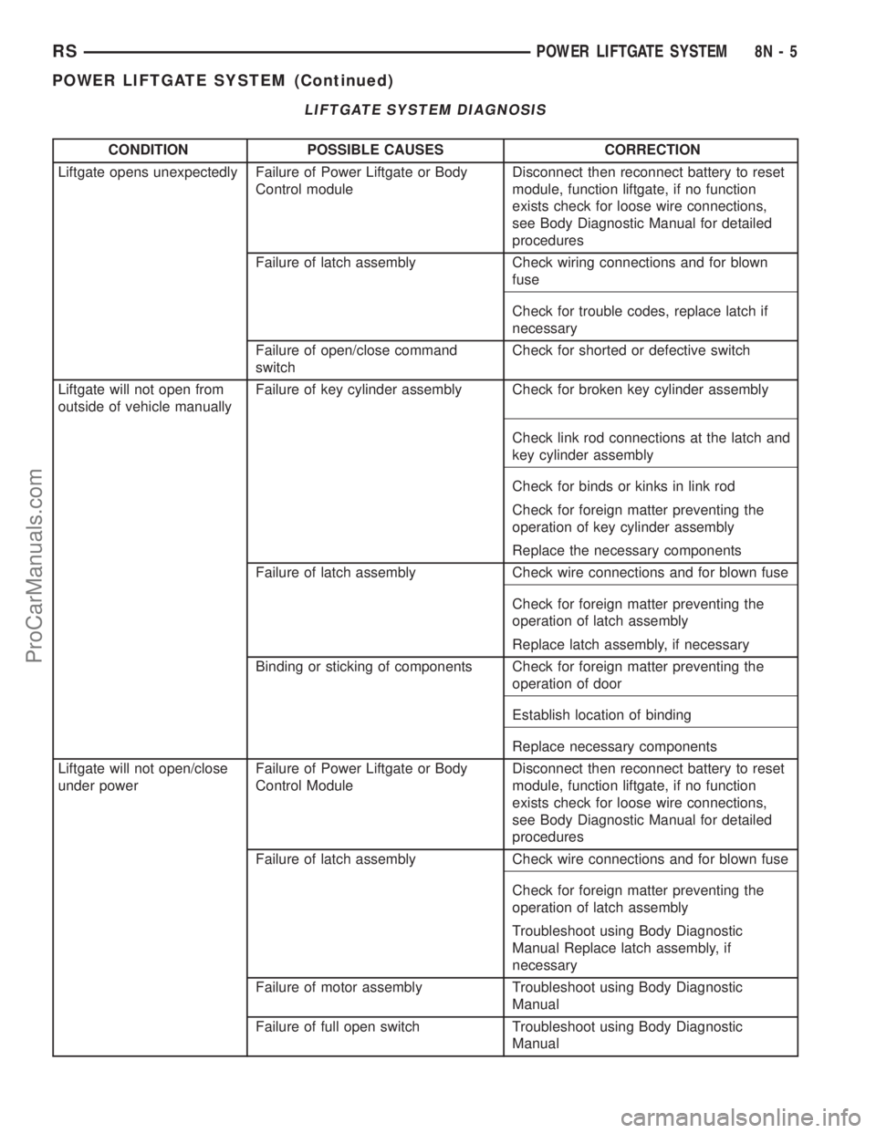
LIFTGATE SYSTEM DIAGNOSIS
CONDITION POSSIBLE CAUSES CORRECTION
Liftgate opens unexpectedly Failure of Power Liftgate or Body
Control moduleDisconnect then reconnect battery to reset
module, function liftgate, if no function
exists check for loose wire connections,
see Body Diagnostic Manual for detailed
procedures
Failure of latch assembly Check wiring connections and for blown
fuse
Check for trouble codes, replace latch if
necessary
Failure of open/close command
switchCheck for shorted or defective switch
Liftgate will not open from
outside of vehicle manuallyFailure of key cylinder assembly Check for broken key cylinder assembly
Check link rod connections at the latch and
key cylinder assembly
Check for binds or kinks in link rod
Check for foreign matter preventing the
operation of key cylinder assembly
Replace the necessary components
Failure of latch assembly Check wire connections and for blown fuse
Check for foreign matter preventing the
operation of latch assembly
Replace latch assembly, if necessary
Binding or sticking of components Check for foreign matter preventing the
operation of door
Establish location of binding
Replace necessary components
Liftgate will not open/close
under powerFailure of Power Liftgate or Body
Control ModuleDisconnect then reconnect battery to reset
module, function liftgate, if no function
exists check for loose wire connections,
see Body Diagnostic Manual for detailed
procedures
Failure of latch assembly Check wire connections and for blown fuse
Check for foreign matter preventing the
operation of latch assembly
Troubleshoot using Body Diagnostic
Manual Replace latch assembly, if
necessary
Failure of motor assembly Troubleshoot using Body Diagnostic
Manual
Failure of full open switch Troubleshoot using Body Diagnostic
Manual
RSPOWER LIFTGATE SYSTEM8N-5
POWER LIFTGATE SYSTEM (Continued)
ProCarManuals.com
Page 550 of 2399

STANDARD PROCEDURE - POWER LIFTGATE
LEARN CYCLE
Any time a power liftgate component is removed,
replaced or a liftgate adjustment is performed a learn
cycle must be performed. This learn cycle enables the
power liftgate control module to learn or relearn
information (travel limits, resistance to door travel,
etc.) which allows it to perform properly and safely.
To perform a learn cycle do the following:
(1) Obtain a DRB IIItscan tool.
(2) Connect the DRB IIItto the vehicle and check
for any power liftgate system stored trouble codes,
correct and erase any stored codes.
(3) Using the DRB IIIt, Go into Test Routine
Menu and select the power open command.
(4) Select the power close command.
(5) The liftgate learn cycle is complete.
If a DRB IIItscan tool is not available the learn
cycle can be performed by actuating the liftgate by
using any of the normal command switches. Be cer-
tain to cycle the liftgate through a complete open and
close cycle before returning the vehicle to service.
NOTE: If the power liftgate will not complete a full
cycle a problem exists with the power liftgate sys-
tem. (Refer to 8 - ELECTRICAL/POWER DOORS -
DIAGNOSIS AND TESTING).
PINCH SENSOR
DESCRIPTION
Vehicles equipped with a power liftgate utilize two
pinch sensors, one is located on each side of the lift-
gate (Fig. 4). These sensors look like weather-strips,
however they consist of pieces of electrically conduc-
tive rubber (tapeswitch), wires, resistor, double sided
tape, and a plastic carrier. They are used to indicate
an obstruction during a power close cycle.
OPERATION
During a power liftgate close cycle, if either of the
two conductive rubber strips (tapeswitch) of the
pinch sensor come in contact with an obstacle, the
pinch sensor circuit is completed. This tells the
power liftgate control module that a obstruction is
felt. The control module will stop the liftgate imme-
diately and return it to the full open position.
REMOVAL
(1) Disconnect and isolate the negative battery
cable.
(2) Remove trim panel from liftgate. Refer to Body
for the procedure.(3) Disconnect the pinch sensor wire harness con-
nector (Fig. 4).
(4) Remove screws holding the pinch sensor to lift-
gate.
(5) Feed the pinch sensor wire harness out of the
liftgate and remove the sensor from the vehicle.
INSTALLATION
(1) Position the pinch sensor and install screws
holding the sensor to the liftgate. Torque screws to
25 in. lbs.
(2) Install wire harness grommet in liftgate flange
and route, connect the pinch sensor wire harness
connector.
(3) Install the trim panel on the liftgate. Refer to
the Body section for the procedure.
(4) Connect the negative battery cable.
(5) Using an appropriate scan tool, check and
erase any power liftgate control module diagnostic
trouble codes related to the pinch sensor.
(6) Verify power liftgate system and pinch sensor
operation. Cycle the power liftgate through one com-
plete open and close cycle, during the final close cycle
press the pinch sensor to verify the power liftgate
detects an obstruction and returns to the full open
position.
Fig. 4 PINCH SENSOR LOCATION
1 - LIFTGATE
2 - PINCH SENSOR ASSEMBLY
3 - POWER LIFTGATE LINK ROD
4 - PINCH SENSOR WIRE HARNESS CONNECTOR
5 - PINCH SENSOR WIRE HARNESS
RSPOWER LIFTGATE SYSTEM8N-9
POWER LIFTGATE SYSTEM (Continued)
ProCarManuals.com
Page 552 of 2399

Serviceable components of the power liftgate gear
motor assembly are the complete gear motor assem-
bly, motor and wire harness, lift gear and control rod,
engage actuator, full open switch and the transverse
bracket. Refer to additional information in this group
for more component details.
OPERATION
With the push of a power liftgate command switch
(liftgate closed), the power liftgate control module
will signal the latch assembly to release the door
from its primary closed and latched position to the
released and movable position. The liftgate motor
mounted, engage actuator then engages the liftgate
motor assembly, which moves the liftgate into the
open position. The liftgate motor provides the torque
and power to move the door to its full open or closed
position(Refer to 8 - ELECTRICAL/POWER DOORS -
OPERATION) for additional information.
REMOVAL
The power liftgate motor can be serviced in two
different ways. The first of which is called out here,
the complete gear motor assembly. The second way
includes the motor, aluminum housing, drive gears
and wire harness assembly. To perform this service
procedure, use the following procedure to remove the
gear motor assembly from the vehicle. Then refer to
the other procedures called out this section to trans-fer the remaining components (engage actuator, full
open switch, transverse bracket and lift gear and
rod) to the replacement motor assembly.
(1) Disconnect and isolate the negative battery
cable.
(2) Remove the left rear D-pillar trim panel from
the vehicle. Refer to the Body section for the proce-
dure.
(3) Disconnect the wire harness connector from the
motor assembly (Fig. 6).
(4) Remove the two bolts from the motor housing
and the one bolt from the transverse mount bracket.
(5) Grab the liftgate motor assembly and lift
upward and out to unhook the motor assembly from
the D-pillar.
(6) Remove the liftgate motor assembly from the
vehicle.
INSTALLATION
(1) Using the motor housing tab, hook the liftgate
motor assembly on the D-pillar.
(2) Install the three motor assembly retaining
bolts. Torque the two rear most bolts first to 9.5 N´m
(85 in. lbs.). Torque the remaining bolt next to the
window actuator to 9.5 N´m (85 in. lbs.).
(3) Connect the liftgate motor assembly electrical
connector.
(4) Install the D-pillar trim panel on the vehicle.
Refer to Body for the procedure.
(5) Connect the negative battery cable.
(6) Using an appropriate scan tool, check any
erase any power liftgate control module diagnostic
trouble codes related to the door motor assembly.
(7) Verify power liftgate system operation. Cycle
the power liftgate through one complete open and
close cycle, this will allow the power liftgate control
module to relearn its cycle with the new components.
ENGAGE ACTUATOR
DESCRIPTION
Vehicles equipped with a power liftgate utilize a
power liftgate engage actuator (Fig. 7). The 12 volt
engage actuator provides the engagement and disen-
gagement of the liftgate gear motor to the lift gear by
way of an over center link, activated by a lever.
The engage actuator is a serviceable component
and cannot be repaired, if found to be faulty it must
be replaced.
OPERATION
The engage actuators normal position is disen-
gaged. When a power liftgate open or close command
is generated from any of the command switches, the
power liftgate control module signals the engage
Fig. 6 POWER LIFTGATE COMPONENTS
1 - POWER LIFTGATE GEAR MOTOR ASSEMBLY
2 - POWER LIFTGATE CONTROL MODULE
3 - ELECTRICAL GROUND LOCATION
RSPOWER LIFTGATE SYSTEM8N-11
LIFTGATE MOTOR (Continued)
ProCarManuals.com
Page 553 of 2399

actuator to move its lever to the engaged position.
This engages the gear motor to the lift gear, so when
the motor turns the lift gate moves upward or down-
wards depending on its current position.
During a manual liftgate open or close cycle the
engage actuator is disengaged, allowing unrestricted
liftgate movement.
REMOVAL
(1) Disconnect and isolate the negative battery
cable.
(2) Remove the left rear D-pillar trim from the
vehicle. Refer to Body for the procedure.
(3) Using your hand manually engage the actuator
link rod, this must be done to access one of the
engage actuator retaining screws.
(4) Remove the two engage actuator retaining
screws (Fig. 8).
(5) Disconnect the engage actuator electrical con-
nector and remove the engage actuator from the
vehicle.
INSTALLATION
(1) Position the engage actuator and connect the
engage actuator electrical connector.
(2) Install the two engage actuator retaining
screws.
(3) Manually disengage the actuator.(4) Install the left rear D-pillar trim on the vehi-
cle. Refer to Body for the procedure.
(5) Connect the negative battery cable.
(6) Using an appropriate scan tool, check and
erase any power liftgate control module diagnostic
trouble codes.
(7) Verify power liftgate system and engage actua-
tor operation. Cycle the power liftgate through one
complete open and close cycle.
TRANSVERSE BRACKET
DESCRIPTION
Vehicles equipped with a power liftgate utilize a
transverse bracket (Fig. 9). This bracket is not differ-
ent than any other metal bracket which is used to
support and secure the power liftgate gear motor
assembly to the vehicles left rear body D-pillar.
The transverse bracket is a serviceable power lift-
gate component. Consult your MoparŸ parts catalog
for a specific part number.
OPERATION
The power liftgate transverse bracket supports the
gear motor assembly by supplying an additional
attachment point. Located on the leading edge of the
gear motor assembly, one end of the transverse
bracket attaches to the motor assembly the other to
the leading edge of the vehicles D-pillar.
Fig. 7 LIFTGATE GEAR MOTOR ASSEMBLY
1 - TRANSVERSE BRACKET
2 - ENGAGE ACTUATOR
3 - LIFT GEAR AND ROD ASSEMBLY
4 - LIFTGATE MOTOR
Fig. 8 LIFTGATE GEAR MOTOR ASSEMBLY
1 - ENGAGE ACTUATOR RETAINING SCREWS
2 - LIFT GEAR RETAINING BOLTS
8N - 12 POWER LIFTGATE SYSTEMRS
ENGAGE ACTUATOR (Continued)
ProCarManuals.com
Page 556 of 2399

OPERATION
On the power cinch/release latch, the latch
mounted actuator provides the torque required to
close the power liftgate from the secondary to the pri-
mary closed and latched position. On the power
cinch/release latch and the power release only latch,
the actuator releases the liftgate from the primary
closed and latched position to the fully unlatched and
movable position.
REMOVAL
(1) Open the hood, disconnect and isolate the neg-
ative battery cable.
(2) Open the liftgate and remove the liftgate trim
panel. Refer to Body for the procedure.
(3) Disconnect the power latch electrical connector
(Fig. 12).
(4) Remove the power latch retaining bolts.
(5) Disconnect the liftgate lock cylinder link rod
from the key cylinder or latch assembly. To discon-
nect from latch, rotate the plastic retaining clip 90 É
to unsnap clip from linkrod. Then pull link rod
straight out of latch arm.
INSTALLATION
(1) Connect the liftgate lock cylinder link rod on
the cinch latch assembly. Rotate the plastic retaining
clip 90 É to lock retaining clip on linkrod.
(2) Connect the link rod on the lock cylinder.
(3) Install the power latch retaining bolts. Torque
to 10 N´m (90 in. lbs.).
(4) Connect the power latch electrical connector
and secure push pin retainers.
(5) Connect the negative battery cable.
(6) Using an appropriate scan tool, check and
erase any power liftgate control module diagnostic
trouble codes related to the power latch.
(7) Verify power liftgate system and power cinch /
release latch operation. Cycle the power liftgate
through one complete open and close cycle, this will
allow the power liftgate control module to relearn its
cycle with the new components.
(8) Verify power liftgate manual operation. Using
liftgate key rotate the lock cylinder to verify door
operation. Pull door open using exterior liftgate han-
dle / switch.
(9) Install the liftgate trim panel. Refer to Body for
the procedure.
LATCH ACTUATOR
DESCRIPTION
Vehicles equipped with a power liftgate utilize a
power cinch latch or power release latch (Fig. 13).
The power cinch and/or power release is made possi-ble by a latch actuator attached to the leading edge
of the power latch assembly. This 12 volt latch actua-
tor contains a small drive gear that meshes with the
latch assemblies internal gears to perform the power
cinch close / power release operations. Refer to the
Latch assembly for more information.
The power cinch/release actuator is serviceable
component. Consult your MoparŸ parts catalog for
specific part numbers.
OPERATION
During a power close cycle, the power cinch actua-
tor provides the torque required to close the power
liftgate from the secondary to the primary closed and
latched position. During a power open cycle, the
power release actuator releases the liftgate from the
primary closed and latched position to the fully
unlatched and movable position.
REMOVAL
(1) Disconnect and isolate the negative battery
cable.
(2) Open the liftgate and remove the lower liftgate
trim panel. Refer to Body for the procedure.
(3) Disconnect the power latch electrical connector
(Fig. 13).
(4) Remove the three latch retaining bolts.
Fig. 13 POWER LATCH ORIENTATION
1 - LATCH & ACTUATOR ASSEMBLY
2 - LATCH ELECTRICAL CONNECTOR
3 - LOCK CYLINDER LINK ROD
4 - LIFTGATE LOCK CYLINDER
RSPOWER LIFTGATE SYSTEM8N-15
LATCH (Continued)
ProCarManuals.com