2002 CHRYSLER VOYAGER engine coolant
[x] Cancel search: engine coolantPage 1469 of 2399
1 second. Therefore, battery voltage is not supplied to
the fuel pump, ignition coil, fuel injectors and heated
oxygen sensors.
ENGINE START-UP MODE
This is an OPEN LOOP mode. If the vehicle is in
park or neutral (automatic transaxles) or the clutch
pedal is depressed (manual transaxles) the ignition
switch energizes the starter relay. The following
actions occur when the starter motor is engaged.
²If the PCM receives the camshaft position sensor
and crankshaft position sensor signals, it energizes
the Auto Shutdown (ASD) relay and fuel pump relay.
If the PCM does not receive both signals within
approximately one second, it will not energize the
ASD relay and fuel pump relay. The ASD and fuel
pump relays supply battery voltage to the fuel pump,
fuel injectors, ignition coil, (EGR solenoid and PCV
heater if equipped) and heated oxygen sensors.
²The PCM energizes the injectors (on the 69É
degree falling edge) for a calculated pulse width until
it determines crankshaft position from the camshaft
position sensor and crankshaft position sensor sig-
nals. The PCM determines crankshaft position within
1 engine revolution.
²After determining crankshaft position, the PCM
begins energizing the injectors in sequence. It adjusts
injector pulse width and controls injector synchroni-
zation by turning the individual ground paths to the
injectors On and Off.
²When the engine idles within 64 RPM of its
target RPM, the PCM compares current MAP sensor
value with the atmospheric pressure value received
during the Ignition Switch On (zero RPM) mode.
Once the ASD and fuel pump relays have been
energized, the PCM determines injector pulse width
based on the following:
²MAP
²Engine RPM
²Battery voltage
²Engine coolant temperature
²Inlet/Intake air temperature (IAT)
²Throttle position
²The number of engine revolutions since cranking
was initiated
During Start-up the PCM maintains ignition tim-
ing at 9É BTDC.
ENGINE WARM-UP MODE
This is an OPEN LOOP mode. The following inputs
are received by the PCM:
²Manifold Absolute Pressure (MAP)
²Crankshaft position (engine speed)
²Engine coolant temperature
²Inlet/Intake air temperature (IAT)
²Camshaft position²Knock sensor
²Throttle position
²A/C switch
²Battery voltage
²Vehicle speed
²Speed control
²O2 sensors
The PCM adjusts injector pulse width and controls
injector synchronization by turning the individual
ground paths to the injectors On and Off.
The PCM adjusts ignition timing and engine idle
speed. Engine idle speed is adjusted through the idle
air control motor.
CRUISE OR IDLE MODE
When the engine is at operating temperature this
is a CLOSED LOOP mode. During cruising or idle
the following inputs are received by the PCM:
²Manifold absolute pressure
²Crankshaft position (engine speed)
²Inlet/Intake air temperature
²Engine coolant temperature
²Camshaft position
²Knock sensor
²Throttle position
²Exhaust gas oxygen content
²A/C control positions
²Battery voltage
²Vehicle speed
The PCM adjusts injector pulse width and controls
injector synchronization by turning the individual
ground paths to the injectors On and Off.
The PCM adjusts engine idle speed and ignition
timing. The PCM adjusts the air/fuel ratio according
to the oxygen content in the exhaust gas (measured
by the upstream and downstream heated oxygen sen-
sor).
The PCM monitors for engine misfire. During
active misfire and depending on the severity, the
PCM either continuously illuminates or flashes the
malfunction indicator lamp (Check Engine light on
instrument panel). Also, the PCM stores an engine
misfire DTC in memory, if 2nd trip with fault.
The PCM performs several diagnostic routines.
They include:
²Oxygen sensor monitor
²Downstream heated oxygen sensor diagnostics
during open loop operation (except for shorted)
²Fuel system monitor
²EGR monitor (if equipped)
²Purge system monitor
²Catalyst efficiency monitor
²All inputs monitored for proper voltage range,
rationality.
²All monitored components (refer to the Emission
section for On-Board Diagnostics).
14 - 18 FUEL INJECTIONRS
FUEL INJECTION (Continued)
ProCarManuals.com
Page 1470 of 2399
The PCM compares the upstream and downstream
heated oxygen sensor inputs to measure catalytic con-
vertor efficiency. If the catalyst efficiency drops below
the minimum acceptable percentage, the PCM stores a
diagnostic trouble code in memory, after 2 trips.
During certain idle conditions, the PCM may enter
a variable idle speed strategy. During variable idle
speed strategy the PCM adjusts engine speed based
on the following inputs.
²A/C sense
²Battery voltage
²Battery temperature or Calculated Battery Tem-
perature
²Engine coolant temperature
²Engine run time
²Inlet/Intake air temperature
²Vehicle mileage
ACCELERATION MODE
This is a CLOSED LOOP mode. The PCM recog-
nizes an abrupt increase in Throttle Position sensor
output voltage or MAP sensor output voltage as a
demand for increased engine output and vehicle
acceleration. The PCM increases injector pulse width
in response to increased fuel demand.
²Wide Open Throttle-open loop
DECELERATION MODE
This is a CLOSED LOOP mode. During decelera-
tion the following inputs are received by the PCM:
²A/C sense
²Battery voltage
²Inlet/Intake air temperature
²Engine coolant temperature
²Crankshaft position (engine speed)
²Exhaust gas oxygen content (upstream heated
oxygen sensor)
²Knock sensor
²Manifold absolute pressure
²Throttle position sensor
²IAC motor (solenoid) control changes in response
to MAP sensor feedback
The PCM may receive a closed throttle input from
the Throttle Position Sensor (TPS) when it senses an
abrupt decrease in manifold pressure. This indicates a
hard deceleration (Open Loop). In response, the PCM
may momentarily turn off the injectors. This helps
improve fuel economy, emissions and engine braking.
WIDE-OPEN-THROTTLE MODE
This is an OPEN LOOP mode. During wide-open-
throttle operation, the following inputs are used by
the PCM:
²Inlet/Intake air temperature
²Engine coolant temperature
²Engine speed
²Knock sensor²Manifold absolute pressure
²Throttle position
When the PCM senses a wide-open-throttle condi-
tion through the Throttle Position Sensor (TPS) it de-
energizes the A/C compressor clutch relay. This
disables the air conditioning system and disables
EGR (if equipped).
The PCM adjusts injector pulse width to supply a
predetermined amount of additional fuel, based on
MAP and RPM.
IGNITION SWITCH OFF MODE
When the operator turns the ignition switch to the
OFF position, the following occurs:
²All outputs are turned off, unless 02 Heater
Monitor test is being run. Refer to the Emission sec-
tion for On-Board Diagnostics.
²No inputs are monitored except for the heated
oxygen sensors. The PCM monitors the heating ele-
ments in the oxygen sensors and then shuts down.
FUEL CORRECTION or ADAPTIVE MEMORIES
DESCRIPTION
In Open Loop, the PCM changes pulse width with-
out feedback from the O2 Sensors. Once the engine
warms up to approximately 30 to 35É F, the PCM
goes into closed loopShort Term Correctionand
utilizes feedback from the O2 Sensors. Closed loop
Long Term Adaptive Memoryis maintained above
170É to 190É F unless the PCM senses wide open
throttle. At that time the PCM returns to Open Loop
operation.
OPERATION
Short Term
The first fuel correction program that begins func-
tioning is the short term fuel correction. This system
corrects fuel delivery in direct proportion to the read-
ings from the Upstream O2 Sensor.
The PCM monitors the air/fuel ratio by using the
input voltage from the O2 Sensor. When the voltage
reaches its preset high or low limit, the PCM begins
to add or remove fuel until the sensor reaches its
switch point. The short term corrections then begin.
The PCM makes a series of quick changes in the
injector pulse-width until the O2 Sensor reaches its
opposite preset limit or switch point. The process
then repeats itself in the opposite direction.
Short term fuel correction will keep increasing or
decreasing injector pulse-width based upon the
upstream O2 Sensor input. The maximum range of
authority for short term memory is 25% (+/-) of base
pulse-width. Short term is violated and is lost when
ignition is turned OFF.
RSFUEL INJECTION14-19
FUEL INJECTION (Continued)
ProCarManuals.com
Page 1478 of 2399
FUEL PUMP RELAY
DESCRIPTION
The fuel pump relay is located in the PDC. The
inside top of the PDC cover has a label showing relay
and fuse location.
OPERATION
The fuel pump relay supplies battery voltage to the
fuel pump. A buss bar in the Power Distribution Cen-
ter (PDC) supplies voltage to the solenoid side and
contact side of the relay. The fuel pump relay power
circuit contains a fuse between the buss bar in the
PDC and the relay. The fuse is located in the PDC.
Refer to the Wiring Diagrams for circuit information.
The PCM controls the fuel pump relay by switch-
ing the ground path for the solenoid side of the relay
on and off. The PCM turns the ground path off when
the ignition switch is in the Off position. When the
ignition switch is in the On position, the PCM ener-
gizes the fuel pump. If the crankshaft position sensor
does not detect engine rotation, the PCM de-ener-
gizes the relay after approximately one second.
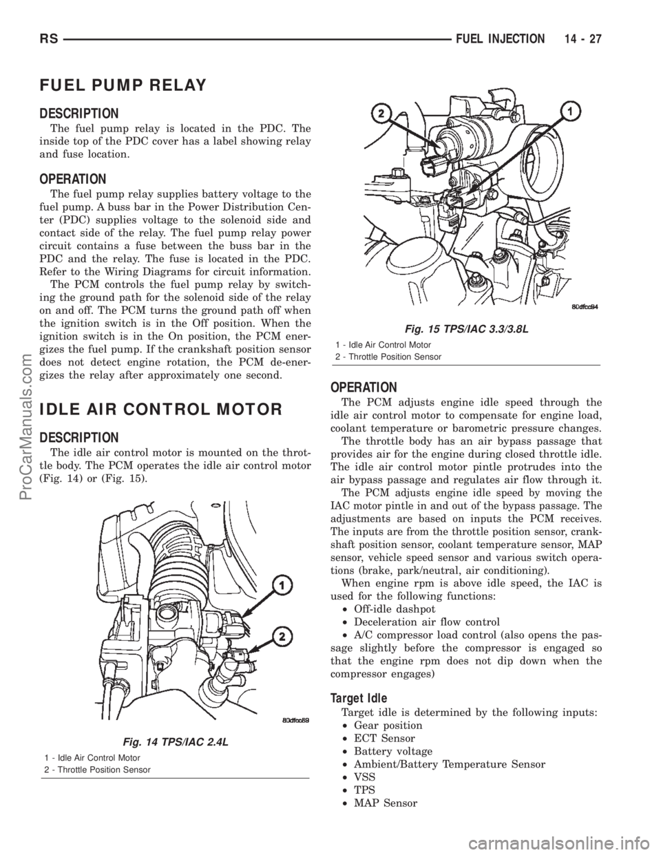
IDLE AIR CONTROL MOTOR
DESCRIPTION
The idle air control motor is mounted on the throt-
tle body. The PCM operates the idle air control motor
(Fig. 14) or (Fig. 15).
OPERATION
The PCM adjusts engine idle speed through the
idle air control motor to compensate for engine load,
coolant temperature or barometric pressure changes.
The throttle body has an air bypass passage that
provides air for the engine during closed throttle idle.
The idle air control motor pintle protrudes into the
air bypass passage and regulates air flow through it.
The PCM adjusts engine idle speed by moving the
IAC motor pintle in and out of the bypass passage. The
adjustments are based on inputs the PCM receives.
The inputs are from the throttle position sensor, crank-
shaft position sensor, coolant temperature sensor, MAP
sensor, vehicle speed sensor and various switch opera-
tions (brake, park/neutral, air conditioning).
When engine rpm is above idle speed, the IAC is
used for the following functions:
²Off-idle dashpot
²Deceleration air flow control
²A/C compressor load control (also opens the pas-
sage slightly before the compressor is engaged so
that the engine rpm does not dip down when the
compressor engages)
Target Idle
Target idle is determined by the following inputs:
²Gear position
²ECT Sensor
²Battery voltage
²Ambient/Battery Temperature Sensor
²VSS
²TPS
²MAP Sensor
Fig. 14 TPS/IAC 2.4L
1 - Idle Air Control Motor
2 - Throttle Position Sensor
Fig. 15 TPS/IAC 3.3/3.8L
1 - Idle Air Control Motor
2 - Throttle Position Sensor
RSFUEL INJECTION14-27
ProCarManuals.com
Page 1684 of 2399
STATOR
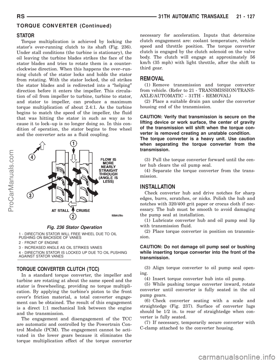
Torque multiplication is achieved by locking the
stator's over-running clutch to its shaft (Fig. 236).
Under stall conditions (the turbine is stationary), the
oil leaving the turbine blades strikes the face of the
stator blades and tries to rotate them in a counter-
clockwise direction. When this happens the over±run-
ning clutch of the stator locks and holds the stator
from rotating. With the stator locked, the oil strikes
the stator blades and is redirected into a ªhelpingº
direction before it enters the impeller. This circula-
tion of oil from impeller to turbine, turbine to stator,
and stator to impeller, can produce a maximum
torque multiplication of about 2.4:1. As the turbine
begins to match the speed of the impeller, the fluid
that was hitting the stator in such as way as to
cause it to lock±up is no longer doing so. In this con-
dition of operation, the stator begins to free wheel
and the converter acts as a fluid coupling.
TORQUE CONVERTER CLUTCH (TCC)
In a standard torque converter, the impeller and
turbine are rotating at about the same speed and the
stator is freewheeling, providing no torque multipli-
cation. By applying the turbine's piston to the front
cover's friction material, a total converter engage-
ment can be obtained. The result of this engagement
is a direct 1:1 mechanical link between the engine
and the transmission.
The engagement and disengagement of the TCC
are automatic and controlled by the Powertrain Con-
trol Module (PCM). The engagement cannot be acti-
vated in the lower gears because it eliminates the
torque multiplication effect of the torque converternecessary for acceleration. Inputs that determine
clutch engagement are: coolant temperature, vehicle
speed and throttle position. The torque converter
clutch is engaged by the clutch solenoid on the valve
body. The clutch will engage at approximately 56
km/h (35 mph) with light throttle, after the shift to
third gear.
REMOVAL
(1) Remove transmission and torque converter
from vehicle. (Refer to 21 - TRANSMISSION/TRANS-
AXLE/AUTOMATIC - 31TH - REMOVAL)
(2) Place a suitable drain pan under the converter
housing end of the transmission.
CAUTION: Verify that transmission is secure on the
lifting device or work surface, the center of gravity
of the transmission will shift when the torque con-
verter is removed creating an unstable condition.
The torque converter is a heavy unit. Use caution
when separating the torque converter from the
transmission.
(3) Pull the torque converter forward until the cen-
ter hub clears the oil pump seal.
(4) Separate the torque converter from the trans-
mission.
INSTALLATION
Check converter hub and drive notches for sharp
edges, burrs, scratches, or nicks. Polish the hub and
notches with 320/400 grit paper or crocus cloth if nec-
essary. The hub must be smooth to avoid damaging
the pump seal at installation.
(1) Lubricate converter hub and oil pump seal lip
with transmission fluid.
(2) Place torque converter in position on transmis-
sion.
CAUTION: Do not damage oil pump seal or bushing
while inserting torque converter into the front of the
transmission.
(3) Align torque converter to oil pump seal open-
ing.
(4) Insert torque converter hub into oil pump.
(5) While pushing torque converter inward, rotate
converter until converter is fully seated in the oil
pump gears.
(6) Check converter seating with a scale and
straightedge (Fig. 237). Surface of converter lugs
should be 1/2 in. to rear of straightedge when con-
verter is fully seated.
(7) If necessary, temporarily secure converter with
C-clamp attached to the converter housing.
Fig. 236 Stator Operation
1 - DIRECTION STATOR WILL FREE WHEEL DUE TO OIL
PUSHING ON BACKSIDE OF VANES
2 - FRONT OF ENGINE
3 - INCREASED ANGLE AS OIL STRIKES VANES
4 - DIRECTION STATOR IS LOCKED UP DUE TO OIL PUSHING
AGAINST STATOR VANES
RS31TH AUTOMATIC TRANSAXLE21 - 127
TORQUE CONVERTER (Continued)
ProCarManuals.com
Page 1846 of 2399
OPERATION
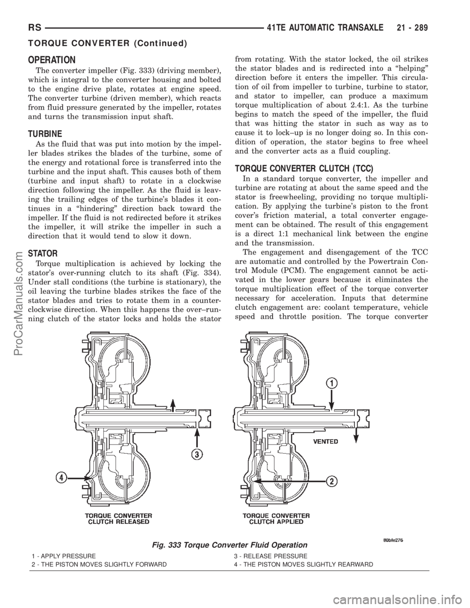
The converter impeller (Fig. 333) (driving member),
which is integral to the converter housing and bolted
to the engine drive plate, rotates at engine speed.
The converter turbine (driven member), which reacts
from fluid pressure generated by the impeller, rotates
and turns the transmission input shaft.
TURBINE
As the fluid that was put into motion by the impel-
ler blades strikes the blades of the turbine, some of
the energy and rotational force is transferred into the
turbine and the input shaft. This causes both of them
(turbine and input shaft) to rotate in a clockwise
direction following the impeller. As the fluid is leav-
ing the trailing edges of the turbine's blades it con-
tinues in a ªhinderingº direction back toward the
impeller. If the fluid is not redirected before it strikes
the impeller, it will strike the impeller in such a
direction that it would tend to slow it down.
STATOR
Torque multiplication is achieved by locking the
stator's over-running clutch to its shaft (Fig. 334).
Under stall conditions (the turbine is stationary), the
oil leaving the turbine blades strikes the face of the
stator blades and tries to rotate them in a counter-
clockwise direction. When this happens the over±run-
ning clutch of the stator locks and holds the statorfrom rotating. With the stator locked, the oil strikes
the stator blades and is redirected into a ªhelpingº
direction before it enters the impeller. This circula-
tion of oil from impeller to turbine, turbine to stator,
and stator to impeller, can produce a maximum
torque multiplication of about 2.4:1. As the turbine
begins to match the speed of the impeller, the fluid
that was hitting the stator in such as way as to
cause it to lock±up is no longer doing so. In this con-
dition of operation, the stator begins to free wheel
and the converter acts as a fluid coupling.
TORQUE CONVERTER CLUTCH (TCC)
In a standard torque converter, the impeller and
turbine are rotating at about the same speed and the
stator is freewheeling, providing no torque multipli-
cation. By applying the turbine's piston to the front
cover's friction material, a total converter engage-
ment can be obtained. The result of this engagement
is a direct 1:1 mechanical link between the engine
and the transmission.
The engagement and disengagement of the TCC
are automatic and controlled by the Powertrain Con-
trol Module (PCM). The engagement cannot be acti-
vated in the lower gears because it eliminates the
torque multiplication effect of the torque converter
necessary for acceleration. Inputs that determine
clutch engagement are: coolant temperature, vehicle
speed and throttle position. The torque converter
Fig. 333 Torque Converter Fluid Operation
1 - APPLY PRESSURE 3 - RELEASE PRESSURE
2 - THE PISTON MOVES SLIGHTLY FORWARD 4 - THE PISTON MOVES SLIGHTLY REARWARD
RS41TE AUTOMATIC TRANSAXLE21 - 289
TORQUE CONVERTER (Continued)
ProCarManuals.com
Page 1849 of 2399
OPERATION
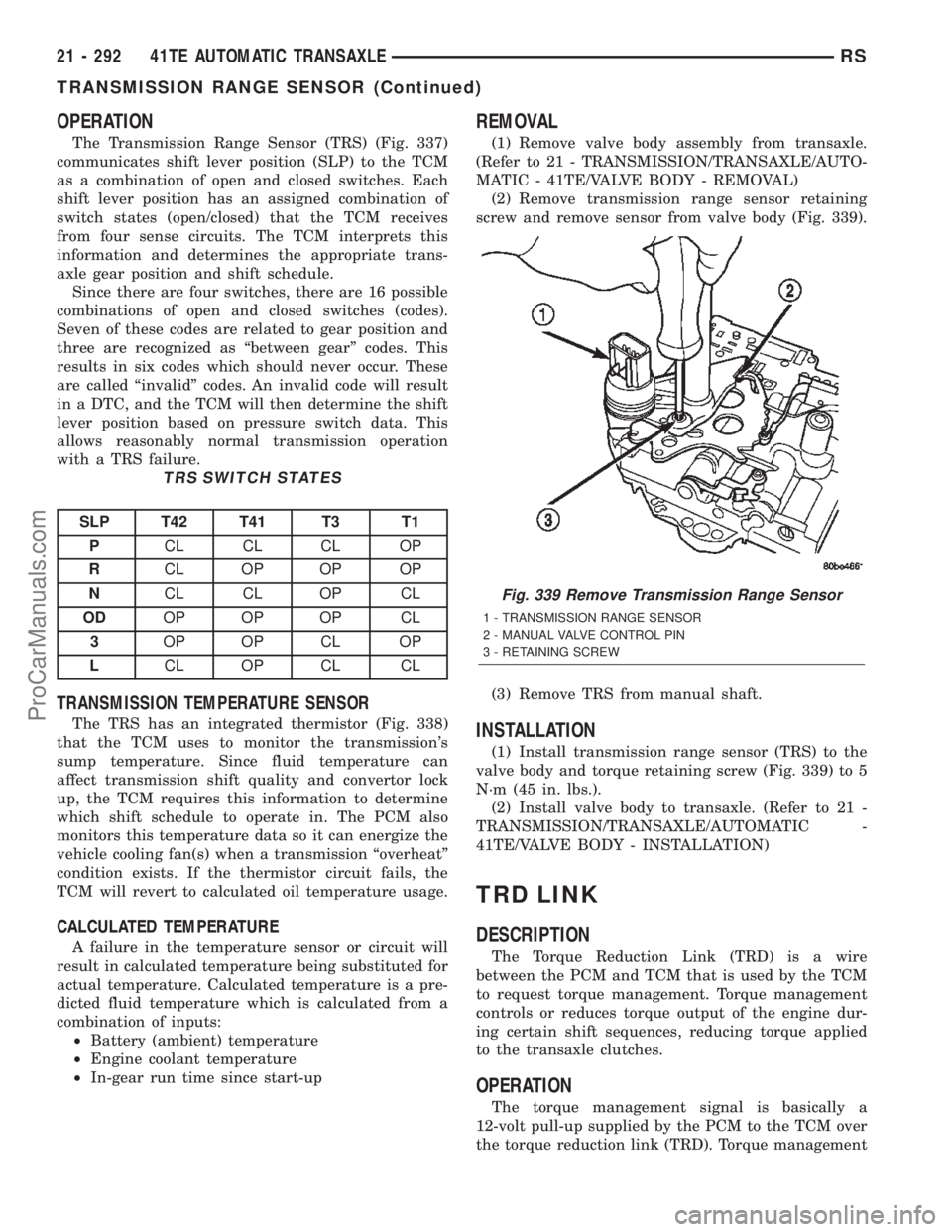
The Transmission Range Sensor (TRS) (Fig. 337)
communicates shift lever position (SLP) to the TCM
as a combination of open and closed switches. Each
shift lever position has an assigned combination of
switch states (open/closed) that the TCM receives
from four sense circuits. The TCM interprets this
information and determines the appropriate trans-
axle gear position and shift schedule.
Since there are four switches, there are 16 possible
combinations of open and closed switches (codes).
Seven of these codes are related to gear position and
three are recognized as ªbetween gearº codes. This
results in six codes which should never occur. These
are called ªinvalidº codes. An invalid code will result
in a DTC, and the TCM will then determine the shift
lever position based on pressure switch data. This
allows reasonably normal transmission operation
with a TRS failure.
TRS SWITCH STATES
SLP T42 T41 T3 T1
PCL CL CL OP
RCL OP OP OP
NCL CL OP CL
ODOP OP OP CL
3OP OP CL OP
LCL OP CL CL
TRANSMISSION TEMPERATURE SENSOR
The TRS has an integrated thermistor (Fig. 338)
that the TCM uses to monitor the transmission's
sump temperature. Since fluid temperature can
affect transmission shift quality and convertor lock
up, the TCM requires this information to determine
which shift schedule to operate in. The PCM also
monitors this temperature data so it can energize the
vehicle cooling fan(s) when a transmission ªoverheatº
condition exists. If the thermistor circuit fails, the
TCM will revert to calculated oil temperature usage.
CALCULATED TEMPERATURE
A failure in the temperature sensor or circuit will
result in calculated temperature being substituted for
actual temperature. Calculated temperature is a pre-
dicted fluid temperature which is calculated from a
combination of inputs:
²Battery (ambient) temperature
²Engine coolant temperature
²In-gear run time since start-up
REMOVAL
(1) Remove valve body assembly from transaxle.
(Refer to 21 - TRANSMISSION/TRANSAXLE/AUTO-
MATIC - 41TE/VALVE BODY - REMOVAL)
(2) Remove transmission range sensor retaining
screw and remove sensor from valve body (Fig. 339).
(3) Remove TRS from manual shaft.
INSTALLATION
(1) Install transmission range sensor (TRS) to the
valve body and torque retaining screw (Fig. 339) to 5
N´m (45 in. lbs.).
(2) Install valve body to transaxle. (Refer to 21 -
TRANSMISSION/TRANSAXLE/AUTOMATIC -
41TE/VALVE BODY - INSTALLATION)
TRD LINK
DESCRIPTION
The Torque Reduction Link (TRD) is a wire
between the PCM and TCM that is used by the TCM
to request torque management. Torque management
controls or reduces torque output of the engine dur-
ing certain shift sequences, reducing torque applied
to the transaxle clutches.
OPERATION
The torque management signal is basically a
12-volt pull-up supplied by the PCM to the TCM over
the torque reduction link (TRD). Torque management
Fig. 339 Remove Transmission Range Sensor
1 - TRANSMISSION RANGE SENSOR
2 - MANUAL VALVE CONTROL PIN
3 - RETAINING SCREW
21 - 292 41TE AUTOMATIC TRANSAXLERS
TRANSMISSION RANGE SENSOR (Continued)
ProCarManuals.com
Page 1878 of 2399
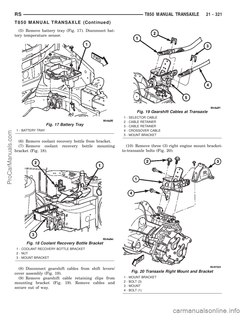
(5) Remove battery tray (Fig. 17). Disconnect bat-
tery temperature sensor.
(6) Remove coolant recovery bottle from bracket.
(7) Remove coolant recovery bottle mounting
bracket (Fig. 18).
(8) Disconnect gearshift cables from shift levers/
cover assembly (Fig. 19).
(9) Remove gearshift cable retaining clips from
mounting bracket (Fig. 19). Remove cables and
secure out of way.(10) Remove three (3) right engine mount bracket-
to-transaxle bolts (Fig. 20).
Fig. 17 Battery Tray
1 - BATTERY TRAY
Fig. 18 Coolant Recovery Bottle Bracket
1 - COOLANT RECOVERY BOTTLE BRACKET
2 - NUT
3 - MOUNT BRACKET
Fig. 19 Gearshift Cables at Transaxle
1 - SELECTOR CABLE
2 - CABLE RETAINER
3 - CABLE RETAINER
4 - CROSSOVER CABLE
5 - MOUNT BRACKET
Fig. 20 Transaxle Right Mount and Bracket
1 - MOUNT BRACKET
2 - BOLT (3)
3 - MOUNT
4 - BOLT (1)
RST850 MANUAL TRANSAXLE21 - 321
T850 MANUAL TRANSAXLE (Continued)
ProCarManuals.com
Page 1896 of 2399
(11) Install halfshafts and front wheel/tire assem-
blies. (Refer to 3 - DIFFERENTIAL & DRIVELINE/
HALF SHAFT - INSTALLATION)
(12) Lower vehicle.
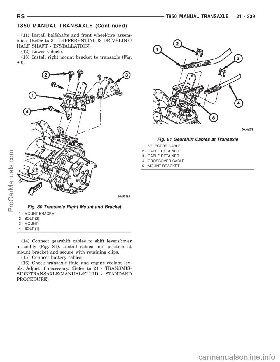
(13) Install right mount bracket to transaxle (Fig.
80).
(14) Connect gearshift cables to shift levers/cover
assembly (Fig. 81). Install cables into position at
mount bracket and secure with retaining clips.
(15) Connect battery cables.
(16) Check transaxle fluid and engine coolant lev-
els. Adjust if necessary. (Refer to 21 - TRANSMIS-
SION/TRANSAXLE/MANUAL/FLUID - STANDARD
PROCEDURE)
Fig. 80 Transaxle Right Mount and Bracket
1 - MOUNT BRACKET
2 - BOLT (3)
3 - MOUNT
4 - BOLT (1)
Fig. 81 Gearshift Cables at Transaxle
1 - SELECTOR CABLE
2 - CABLE RETAINER
3 - CABLE RETAINER
4 - CROSSOVER CABLE
5 - MOUNT BRACKET
RST850 MANUAL TRANSAXLE21 - 339
T850 MANUAL TRANSAXLE (Continued)
ProCarManuals.com