2002 CHRYSLER VOYAGER clutch
[x] Cancel search: clutchPage 1590 of 2399
(5) Line pressure should read 52 to 58 psi with
throttle lever clockwise. Pressure should gradually
increase to 80 to 88 psi.as lever is moved counter-
clockwise.
(6) Low/reverse pressure should read the same as
line pressure, within 3 psi.
(7) This tests pump output, pressure regulation,
and condition of rear clutch and rear servo hydraulic
circuits.
TEST TWO (SELECTOR IN 2)
(1) Attach one gauge to line pressure port, and tee
another gauge into lower cooler line fitting. This will
allow lubrication pressure readings to be taken.
(2) Operate engine at 1000 rpm for test.
(3) Move selector lever on transaxle one detent for-
ward from full rearward position. This is selector 2
position.
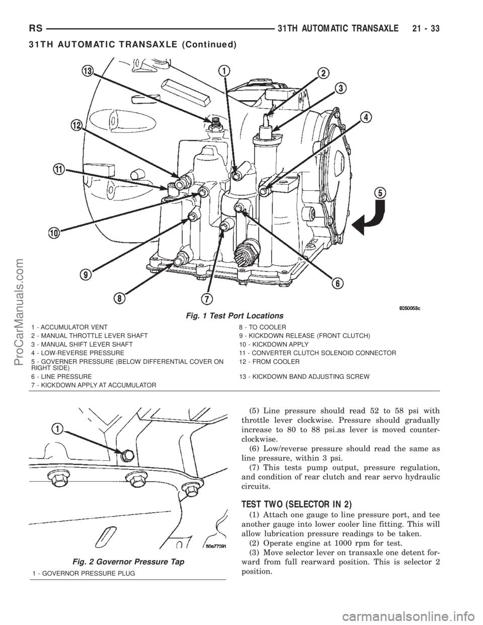
Fig. 1 Test Port Locations
1 - ACCUMULATOR VENT 8 - TO COOLER
2 - MANUAL THROTTLE LEVER SHAFT 9 - KICKDOWN RELEASE (FRONT CLUTCH)
3 - MANUAL SHIFT LEVER SHAFT 10 - KICKDOWN APPLY
4 - LOW-REVERSE PRESSURE 11 - CONVERTER CLUTCH SOLENOID CONNECTOR
5 - GOVERNER PRESSURE (BELOW DIFFERENTIAL COVER ON
RIGHT SIDE)12 - FROM COOLER
6 - LINE PRESSURE 13 - KICKDOWN BAND ADJUSTING SCREW
7 - KICKDOWN APPLY AT ACCUMULATOR
Fig. 2 Governor Pressure Tap
1 - GOVERNOR PRESSURE PLUG
RS31TH AUTOMATIC TRANSAXLE21-33
31TH AUTOMATIC TRANSAXLE (Continued)
ProCarManuals.com
Page 1591 of 2399
(4) Read pressures on both gauges as throttle lever
on transaxle is moved from full clockwise position to
full counterclockwise position.
(5) Line pressure should read 52 to 58 psi with
throttle lever clockwise. Pressure should gradually
increase to 80 to 88 psi. as lever is moved counter-
clockwise.
(6) Lubrication pressure should be 10 to 25 psi
with lever clockwise and 10 to 35 psi with lever at
full counterclockwise.
(7) This tests pump output, pressure regulation,
and condition of rear clutch and lubrication hydraulic
circuits.
TEST THREE (SELECTOR IN D)
(1) Attach gauges to line and kickdown release
ports.
(2) Operate engine at 1600 rpm for test.
(3) Move selector lever on transaxle two detents
forward from full rearward position. This is selector
D position.
(4) Read pressures on both gauges as throttle lever
on transaxle is moved from full clockwise to the full
counterclockwise position.
(5) Line pressure should read 52 to 58 psi with
throttle lever clockwise. Pressure should gradually
increase to 80 to 88 psi. as lever is moved counter-
clockwise.
(6) Kickdown release is pressurized only in direct
drive and should be same as line pressure within 3
psi, up to kickdown point.
(7) This tests pump output, pressure regulation,
and condition of rear clutch, front clutch, and
hydraulic circuits.
TEST FOUR (SELECTOR IN REVERSE)
(1) Attach 300 psi gauge (C-3292SP) to low-reverse
port.
(2) Operate engine at 1600 rpm for test.
(3) Move selector lever on transaxle four detents
forward from full rearward position. This is selector
R position.
(4) Low/reverse pressure should read 180 to 220
psi with throttle lever clockwise. Pressure should
gradually increase to 260 to 300 psi. as lever is
moved counterclockwise.(5) This tests pump output, pressure regulation,
and condition of front clutch and rear servo hydraulic
circuits.
(6) Move selector lever on transaxle to D position
to check that low/reverse pressure drops to zero.
(7) This tests for leakage into rear servo, due to
case porosity, which can cause reverse band burn out.
TEST RESULT INDICATIONS
(1) If proper line pressure, minimum to maximum,
is found in any one test, the pump and pressure reg-
ulator are working properly.
(2) Low pressure in D, 1, and 2 but correct pres-
sure in R, indicates rear clutch circuit leakage.
(3) Low pressure in D and R, but correct pressure
in 1 indicates front clutch circuit leakage.
(4) Low pressure in R and 1, but correct pressure
in 2 indicates rear servo circuit leakage.
(5) Low line pressure in all positions indicates a
defective pump, a clogged filter, or a stuck pressure
regulator valve.
GOVERNOR PRESSURE
Test only if transaxle shifts at wrong vehicle
speeds when throttle cable is correctly adjusted.
(1) Connect a 100 psi gauge to governor pressure
port. It is located at lower right side of case, below
differential cover (Fig. 2).
(2) Operate transaxle in third gear to read pres-
sures. The governor pressure should respond
smoothly to changes in mph and should return to 0
to 3 psi when vehicle is stopped. High pressure
(above 3 psi) at standstill will prevent the transaxle
from downshifting.
THROTTLE PRESSURE
No gauge port is provided for throttle pressure.
Incorrect throttle pressure should be suspected if
part throttle upshift speeds are either delayed or
occur too early in relation to vehicle speed. Engine
runaway on shifts can also be an indicator of low
throttle pressure setting, or misadjusted throttle
cable.
In no case should throttle pressure be adjusted
until the transaxle throttle cable adjustment has
been verified to be correct.
21 - 34 31TH AUTOMATIC TRANSAXLERS
31TH AUTOMATIC TRANSAXLE (Continued)
ProCarManuals.com
Page 1592 of 2399
DIAGNOSIS AND TESTING - TORQUE
CONVERTER HOUSING FLUID LEAKAGE
When diagnosing converter housing fluid leaks,
three actions must be taken before repair:
(1) Verify proper transmission fluid level.
(2) Verify that the leak originates from the con-
verter housing area and is transmission fluid.
(3) Determine the true source of the leak.
Fluid leakage at or around the torque converter
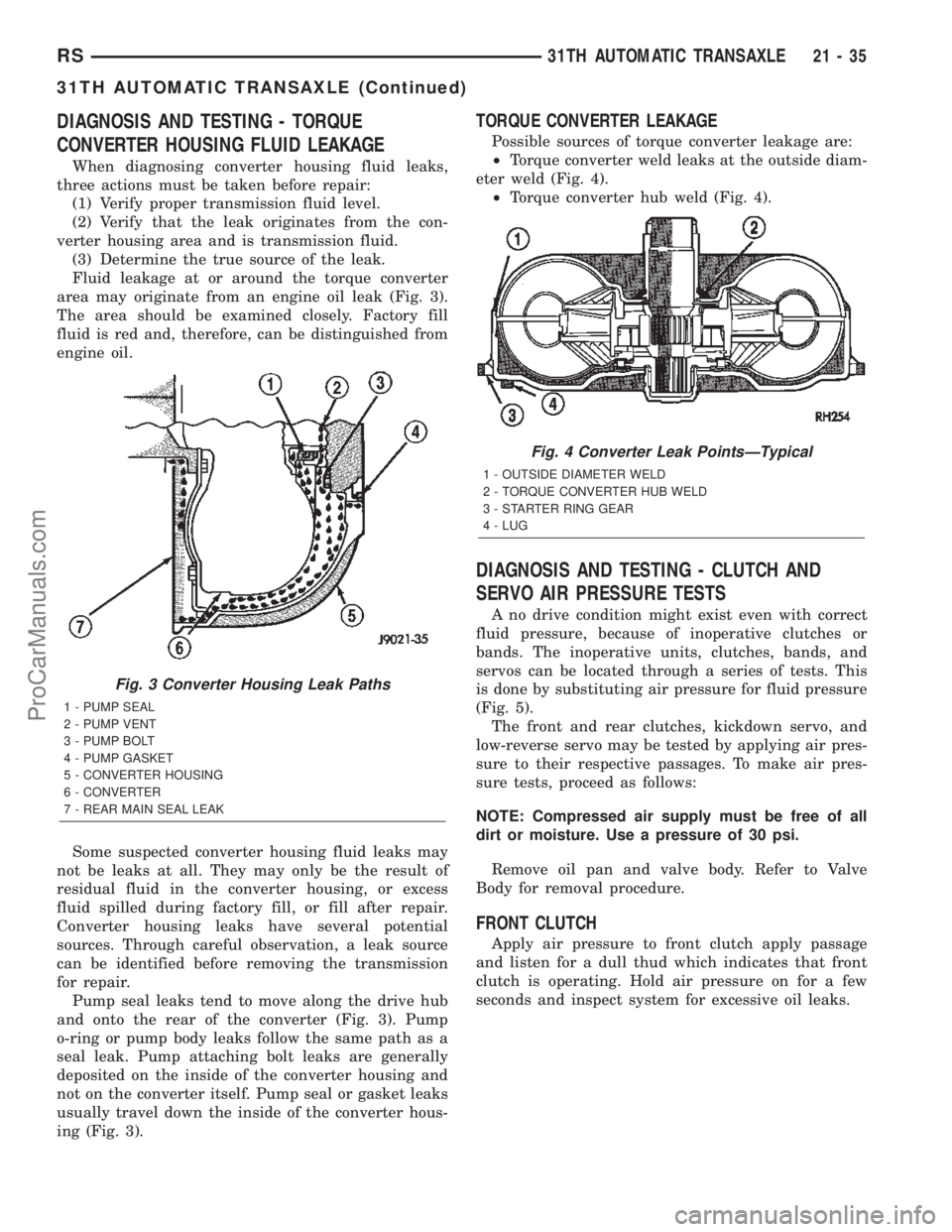
area may originate from an engine oil leak (Fig. 3).
The area should be examined closely. Factory fill
fluid is red and, therefore, can be distinguished from
engine oil.
Some suspected converter housing fluid leaks may
not be leaks at all. They may only be the result of
residual fluid in the converter housing, or excess
fluid spilled during factory fill, or fill after repair.
Converter housing leaks have several potential
sources. Through careful observation, a leak source
can be identified before removing the transmission
for repair.
Pump seal leaks tend to move along the drive hub
and onto the rear of the converter (Fig. 3). Pump
o-ring or pump body leaks follow the same path as a
seal leak. Pump attaching bolt leaks are generally
deposited on the inside of the converter housing and
not on the converter itself. Pump seal or gasket leaks
usually travel down the inside of the converter hous-
ing (Fig. 3).
TORQUE CONVERTER LEAKAGE
Possible sources of torque converter leakage are:
²Torque converter weld leaks at the outside diam-
eter weld (Fig. 4).
²Torque converter hub weld (Fig. 4).
DIAGNOSIS AND TESTING - CLUTCH AND
SERVO AIR PRESSURE TESTS
A no drive condition might exist even with correct
fluid pressure, because of inoperative clutches or
bands. The inoperative units, clutches, bands, and
servos can be located through a series of tests. This
is done by substituting air pressure for fluid pressure
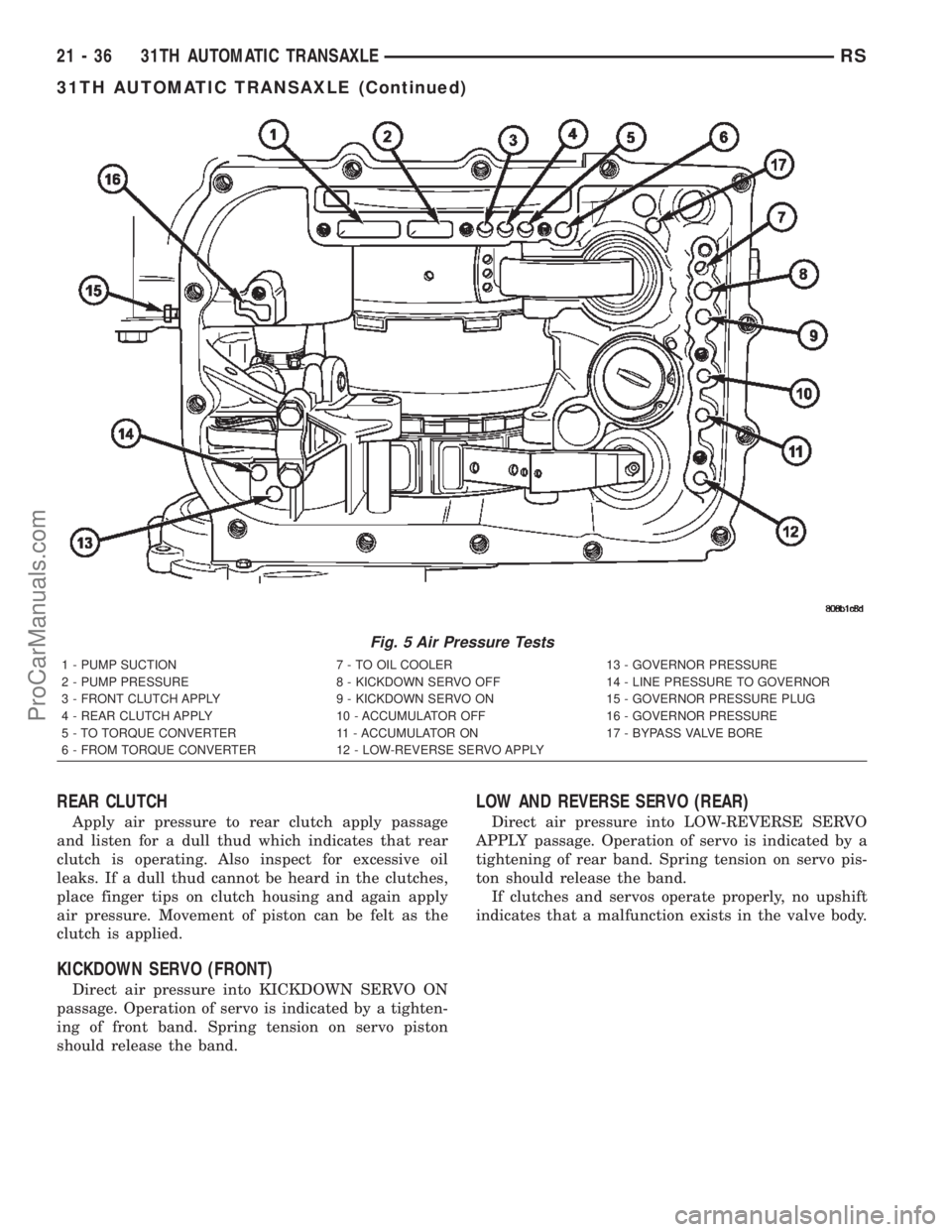
(Fig. 5).
The front and rear clutches, kickdown servo, and
low-reverse servo may be tested by applying air pres-
sure to their respective passages. To make air pres-
sure tests, proceed as follows:
NOTE: Compressed air supply must be free of all
dirt or moisture. Use a pressure of 30 psi.
Remove oil pan and valve body. Refer to Valve
Body for removal procedure.
FRONT CLUTCH
Apply air pressure to front clutch apply passage
and listen for a dull thud which indicates that front
clutch is operating. Hold air pressure on for a few
seconds and inspect system for excessive oil leaks.
Fig. 3 Converter Housing Leak Paths
1 - PUMP SEAL
2 - PUMP VENT
3 - PUMP BOLT
4 - PUMP GASKET
5 - CONVERTER HOUSING
6 - CONVERTER
7 - REAR MAIN SEAL LEAK
Fig. 4 Converter Leak PointsÐTypical
1 - OUTSIDE DIAMETER WELD
2 - TORQUE CONVERTER HUB WELD
3 - STARTER RING GEAR
4 - LUG
RS31TH AUTOMATIC TRANSAXLE21-35
31TH AUTOMATIC TRANSAXLE (Continued)
ProCarManuals.com
Page 1593 of 2399
REAR CLUTCH
Apply air pressure to rear clutch apply passage
and listen for a dull thud which indicates that rear
clutch is operating. Also inspect for excessive oil
leaks. If a dull thud cannot be heard in the clutches,
place finger tips on clutch housing and again apply
air pressure. Movement of piston can be felt as the
clutch is applied.
KICKDOWN SERVO (FRONT)
Direct air pressure into KICKDOWN SERVO ON
passage. Operation of servo is indicated by a tighten-
ing of front band. Spring tension on servo piston
should release the band.
LOW AND REVERSE SERVO (REAR)
Direct air pressure into LOW-REVERSE SERVO
APPLY passage. Operation of servo is indicated by a
tightening of rear band. Spring tension on servo pis-
ton should release the band.
If clutches and servos operate properly, no upshift
indicates that a malfunction exists in the valve body.
Fig. 5 Air Pressure Tests
1 - PUMP SUCTION 7 - TO OIL COOLER 13 - GOVERNOR PRESSURE
2 - PUMP PRESSURE 8 - KICKDOWN SERVO OFF 14 - LINE PRESSURE TO GOVERNOR
3 - FRONT CLUTCH APPLY 9 - KICKDOWN SERVO ON 15 - GOVERNOR PRESSURE PLUG
4 - REAR CLUTCH APPLY 10 - ACCUMULATOR OFF 16 - GOVERNOR PRESSURE
5 - TO TORQUE CONVERTER 11 - ACCUMULATOR ON 17 - BYPASS VALVE BORE
6 - FROM TORQUE CONVERTER 12 - LOW-REVERSE SERVO APPLY
21 - 36 31TH AUTOMATIC TRANSAXLERS
31TH AUTOMATIC TRANSAXLE (Continued)
ProCarManuals.com
Page 1594 of 2399
STANDARD PROCEDURE - ALUMINUM
THREAD REPAIR
Damaged or worn threads in the aluminum trans-
axle case and valve body can be repaired by the use
of Heli-Coils, or equivalent. This repair consists of
drilling out the worn-out damaged threads. Then tap-
ping the hole with a Heli-Coil tap, or equivalent, and
installing a Heli-Coil insert, or equivalent, into the
hole. This brings the hole back to its original thread
size.
Heli-Coil, or equivalent, tools and inserts are
readily available from most automotive parts suppli-
ers.
REMOVAL
(1) Disconnect battery negative cable.
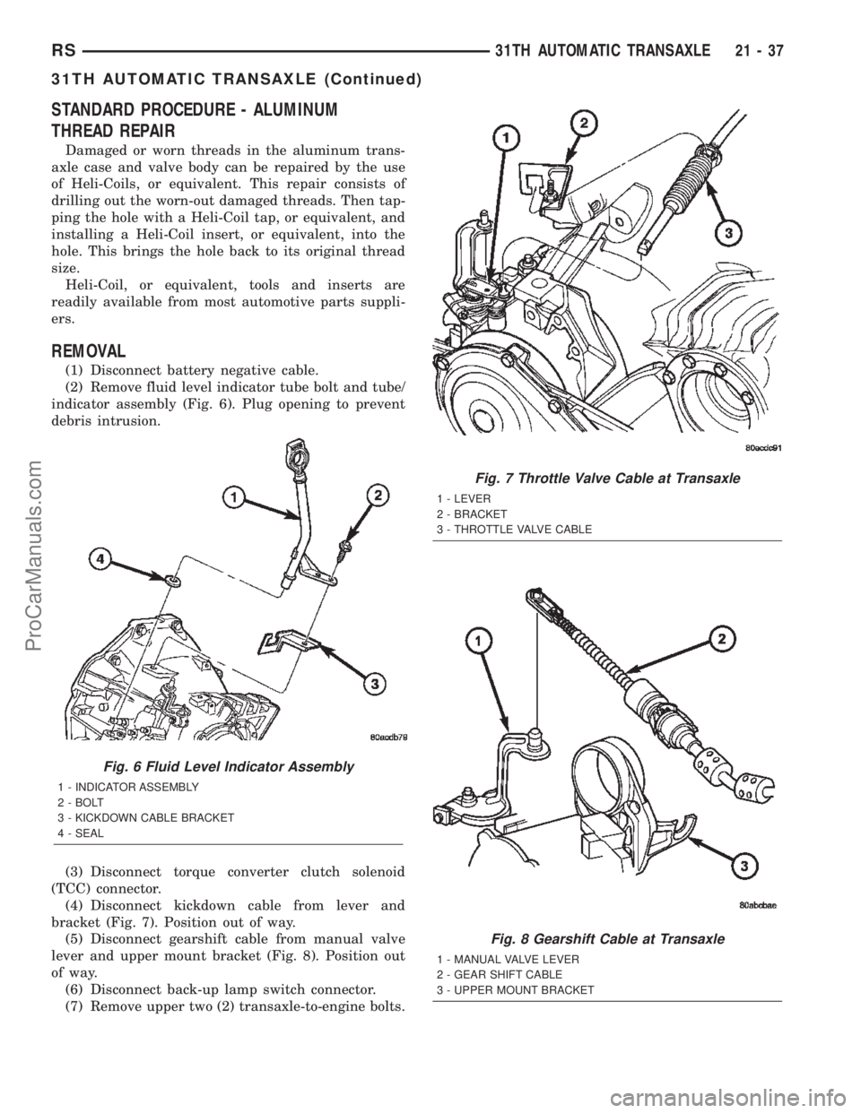
(2) Remove fluid level indicator tube bolt and tube/
indicator assembly (Fig. 6). Plug opening to prevent
debris intrusion.
(3) Disconnect torque converter clutch solenoid
(TCC) connector.
(4) Disconnect kickdown cable from lever and
bracket (Fig. 7). Position out of way.
(5) Disconnect gearshift cable from manual valve
lever and upper mount bracket (Fig. 8). Position out
of way.
(6) Disconnect back-up lamp switch connector.
(7) Remove upper two (2) transaxle-to-engine bolts.
Fig. 6 Fluid Level Indicator Assembly
1 - INDICATOR ASSEMBLY
2 - BOLT
3 - KICKDOWN CABLE BRACKET
4 - SEAL
Fig. 7 Throttle Valve Cable at Transaxle
1 - LEVER
2 - BRACKET
3 - THROTTLE VALVE CABLE
Fig. 8 Gearshift Cable at Transaxle
1 - MANUAL VALVE LEVER
2 - GEAR SHIFT CABLE
3 - UPPER MOUNT BRACKET
RS31TH AUTOMATIC TRANSAXLE21-37
31TH AUTOMATIC TRANSAXLE (Continued)
ProCarManuals.com
Page 1604 of 2399
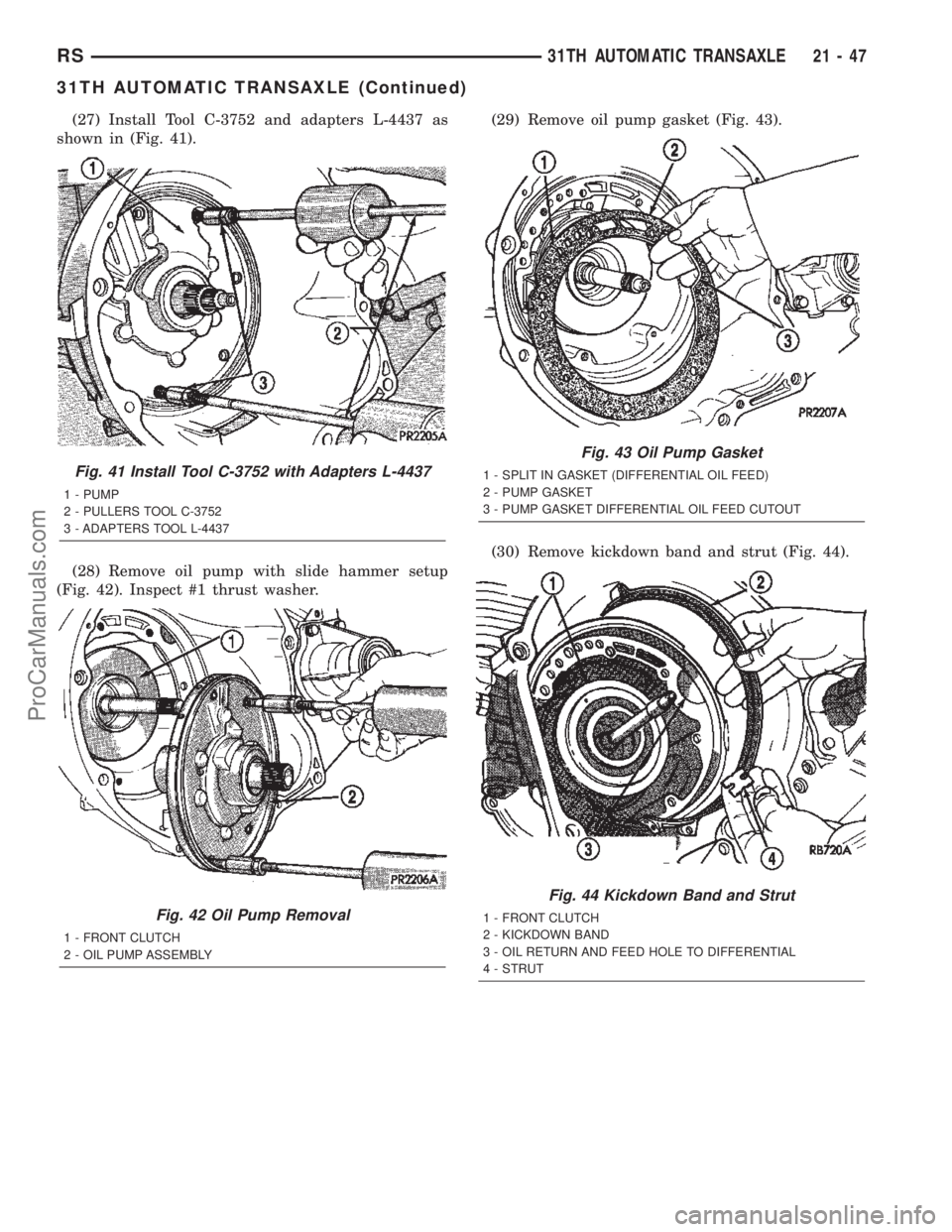
(27) Install Tool C-3752 and adapters L-4437 as
shown in (Fig. 41).
(28) Remove oil pump with slide hammer setup
(Fig. 42). Inspect #1 thrust washer.(29) Remove oil pump gasket (Fig. 43).
(30) Remove kickdown band and strut (Fig. 44).
Fig. 41 Install Tool C-3752 with Adapters L-4437
1 - PUMP
2 - PULLERS TOOL C-3752
3 - ADAPTERS TOOL L-4437
Fig. 42 Oil Pump Removal
1 - FRONT CLUTCH
2 - OIL PUMP ASSEMBLY
Fig. 43 Oil Pump Gasket
1 - SPLIT IN GASKET (DIFFERENTIAL OIL FEED)
2 - PUMP GASKET
3 - PUMP GASKET DIFFERENTIAL OIL FEED CUTOUT
Fig. 44 Kickdown Band and Strut
1 - FRONT CLUTCH
2 - KICKDOWN BAND
3 - OIL RETURN AND FEED HOLE TO DIFFERENTIAL
4 - STRUT
RS31TH AUTOMATIC TRANSAXLE21-47
31TH AUTOMATIC TRANSAXLE (Continued)
ProCarManuals.com
Page 1605 of 2399
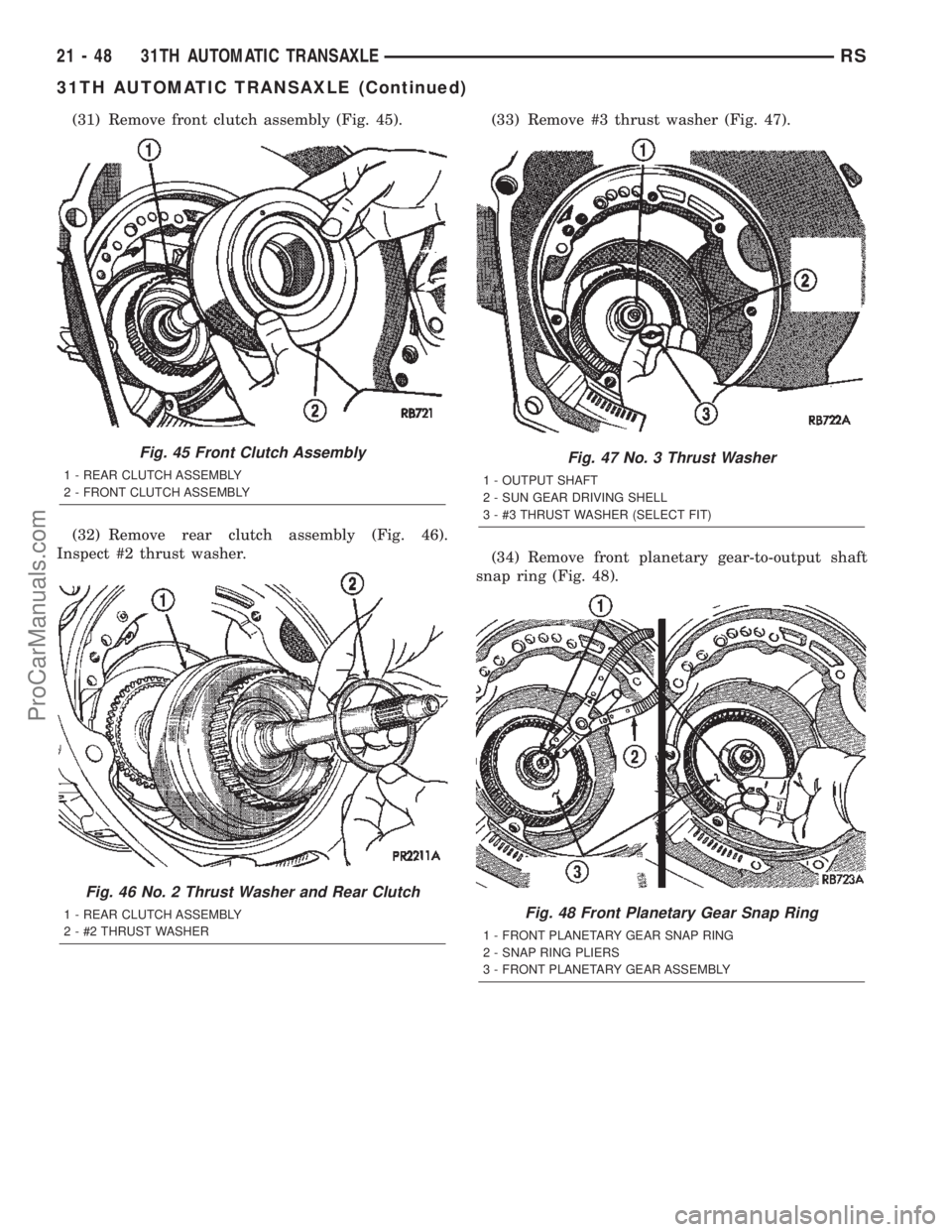
(31) Remove front clutch assembly (Fig. 45).
(32) Remove rear clutch assembly (Fig. 46).
Inspect #2 thrust washer.(33) Remove #3 thrust washer (Fig. 47).
(34) Remove front planetary gear-to-output shaft
snap ring (Fig. 48).
Fig. 45 Front Clutch Assembly
1 - REAR CLUTCH ASSEMBLY
2 - FRONT CLUTCH ASSEMBLY
Fig. 46 No. 2 Thrust Washer and Rear Clutch
1 - REAR CLUTCH ASSEMBLY
2 - #2 THRUST WASHER
Fig. 47 No. 3 Thrust Washer
1 - OUTPUT SHAFT
2 - SUN GEAR DRIVING SHELL
3 - #3 THRUST WASHER (SELECT FIT)
Fig. 48 Front Planetary Gear Snap Ring
1 - FRONT PLANETARY GEAR SNAP RING
2 - SNAP RING PLIERS
3 - FRONT PLANETARY GEAR ASSEMBLY
21 - 48 31TH AUTOMATIC TRANSAXLERS
31TH AUTOMATIC TRANSAXLE (Continued)
ProCarManuals.com
Page 1607 of 2399
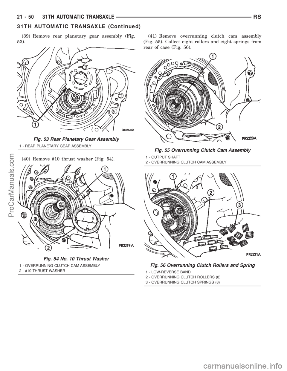
(39) Remove rear planetary gear assembly (Fig.
53).
(40) Remove #10 thrust washer (Fig. 54).(41) Remove overrunning clutch cam assembly
(Fig. 55). Collect eight rollers and eight springs from
rear of case (Fig. 56).
Fig. 53 Rear Planetary Gear Assembly
1 - REAR PLANETARY GEAR ASSEMBLY
Fig. 54 No. 10 Thrust Washer
1 - OVERRUNNING CLUTCH CAM ASSEMBLY
2 - #10 THRUST WASHER
Fig. 55 Overrunning Clutch Cam Assembly
1 - OUTPUT SHAFT
2 - OVERRUNNING CLUTCH CAM ASSEMBLY
Fig. 56 Overrunning Clutch Rollers and Spring
1 - LOW-REVERSE BAND
2 - OVERRUNNING CLUTCH ROLLERS (8)
3 - OVERRUNNING CLUTCH SPRINGS (8)
21 - 50 31TH AUTOMATIC TRANSAXLERS
31TH AUTOMATIC TRANSAXLE (Continued)
ProCarManuals.com