2002 CHRYSLER TOWN AND COUNTRY liftgate
[x] Cancel search: liftgatePage 19 of 2399

²The use of fuel additives which are now being
sold as octane enhancers is not recommended. Most
of these products contain high concentrations of
methanol. Fuel system damage or vehicle perfor-
mance problems resulting from the use of such fuels
or additives is not the responsibility of
DaimlerChrysler Corporation and may not be covered
under the new vehicle warranty.
NOTE: Intentional tampering with emissions control
systems can result in civil penalties being assessed
against you.
DESCRIPTION - FUEL REQUIREMENTS -
DIESEL ENGINE
WARNING: DO NOT USE ALCOHOL OR GASOLINE
AS A FUEL BLENDING AGENT. THEY CAN BE
UNSTABLE UNDER CERTAIN CONDITIONS AND
HAZARDOUS OR EXPLOSIVE WHEN MIXED WITH
DIESEL FUEL.
Use good quality diesel fuel from a reputable sup-
plier. For most year-round service, number 2 diesel
fuel meeting ASTM specification D-975 will provide
good performance. If the vehicle is exposed to
extreme cold (below -18ÉC/0ÉF) or is required to oper-
ate at colder than normal conditions for prolonged
periods, use climatize No. 2 diesel fuel or dilute the
No. 2 diesel fuel with 50% No. 1 diesel fuel. This will
provide better protection from fuel gelling or wax
plugging of the fuel filters.
Diesel fuel is seldom completely free of water. To
prevent fuel system trouble, including fuel line freez-
ing in winter, drain the accumulated water from the
fuel/water separator using the fuel/water separator
drain provided. If you buy good quality fuel and fol-
low the cold weather advice above, fuel conditioners
should not be required in your vehicle. If available in
your area, a high cetane ªpremiumº diesel fuel may
offer improved cold starting and warm up perfor-
mance.
DESCRIPTION - ENGINE OIL - DIESEL
ENGINES
Use only Diesel Engine Oil meeting standardMIL-
2104Cor API ClassificationCD or higherorCCML
D4, D5.
SAE VISCOSITY GRADE
CAUTION: Low viscosity oils must have the proper
API quality or the CCMC G5 designation.
To assure of properly formulated engine oils, it is
recommended that SAE Grade 10W-40 engine oilsthat meet Chrysler material standard MS-6395, be
used. European Grade 10W-40 oils are also accept-
able.
Oils of the SAE 5W-40 or 8W-80 grade number are
preferred when minimum temperatures consistently
fall below -12ÉC.
FLUID FILL/CHECK
LOCATIONS
DESCRIPTION
The fluid check/fill point locations are located in
each applicable service manual section.
LUBRICATION POINTS
DESCRIPTION
Lubrication point locations are located in each
applicable Sections.
MAINTENANCE SCHEDULES
DESCRIPTION
9Maintenance Schedule Information not included in
this section, is located in the appropriate Owner's
Manual.9
HOISTING
STANDARD PROCEDURE - HOISTING
Refer to Owner's Manual provided with vehicle for
proper emergency jacking procedures.
WARNING: THE HOISTING AND JACK LIFTING
POINTS PROVIDED ARE FOR A COMPLETE VEHI-
CLE. WHEN THE ENGINE OR REAR SUSPENSION
IS REMOVED FROM A VEHICLE, THE CENTER OF
GRAVITY IS ALTERED MAKING SOME HOISTING
CONDITIONS UNSTABLE. PROPERLY SUPPORT OR
SECURE VEHICLE TO HOISTING DEVICE WHEN
THESE CONDITIONS EXIST.
CAUTION: Do not position hoisting device on any
suspension component, including the front suspen-
sion crossmember, the rear leaf springs, and the
rear axle. Do not hoist on the front and rear
bumpers, the lower liftgate crossmember, the lower
radiator crossmember, the down standing flanges
on the sill or the front engine mount.
FOR PROPER HOIST PLACEMENT REFER
TO (Fig. 5).
0 - 6 LUBRICATION & MAINTENANCERS
FLUID TYPES (Continued)
ProCarManuals.com
Page 332 of 2399

Any diagnosis of the Audio system should
begin with the use of the DRB IIItdiagnostic
tool. For information on the use of the DRB
IIIt, refer to the appropriate Diagnostic Service
Manual.
Refer to the appropriate wiring information. The
wiring information includes wiring diagrams, proper
wire and connector repair procedures, details of wire
harness routing and retention, connector pin-out
information and location views for the various wire
harness connectors, splices and grounds.
CAUTION: The speaker output of the radio is a
ªfloating groundº system. Do not allow any speaker
lead to short to ground, as damage to the radio
may result.
(1) If all speakers are inoperative, check the radio
fuses in the junction block. If OK, go to Step 2. If not
OK, repair the shorted circuit or component as
required and replace the faulty fuse.
(2) Turn the ignition switch to the ON position.
Turn the radio receiver ON. Adjust the balance and
fader control controls to check the performance of
each individual speaker. Note the speaker locations
that are not performing correctly. Go to Step 3.
(3) Turn the radio receiver OFF. Turn the ignition
OFF. Disconnect and isolate the battery negative
cable. Remove the radio receiver.
(4) Check both the speaker feed (+) circuit and
return (-) circuit cavities for the inoperative speaker
at the radio receiver wire harness connector for con-
tinuity to ground. There should be no continuity. If
OK, go to Step 5. If not OK, repair the shorted
speaker feed (+) and/or return (-) circuits(s) to the
speaker as required.
(5) Disconnect wire harness connector at the inop-
erative speaker. Check for continuity between the
speaker feed (+) circuit cavities of the radio receiver
wire harness connector. Repeat the check between
the speaker return (-) circuit cavities of the radio
receiver wire harness connector and the speaker wire
harness connector. In each case, there should be con-
tinuity. If OK, replace the faulty speaker. If not OK,
repair the open speaker feed (+) and/or return (-) cir-
cuits(s) as required.
REMOVAL
D-PILLAR SPEAKER
(1)Disconnect and isolate the battery negative cable.
(2) Remove rear header trim (right side speaker).
(3) Remove jack cover (left side speaker).
(4) Remove liftgate scuff plate.
(5) Remove upper seat belt bolt. (Refer to 8 -
ELECTRICAL/RESTRAINTS/SEAT BELT OUT-
BOARD FRONT - REMOVAL).(6) Partially remove quarter trim panel to access
the D-pillar speaker.
(7) Slide the speaker from the retainer (Fig. 12).
(8) Disconnect the wire harness connector from the
speaker.
FRONT DOOR SPEAKER
(1)Disconnect and isolate the battery negative cable.
(2)Remove the front door trim panel. (Refer to 23 -
BODY/DOOR - FRONT/TRIM PANEL - REMOVAL).
(3) Remove the speaker mounting screws (Fig. 13).
(4) Disconnect wire harness connector and remove
speaker from door.
Fig. 12 D-PILLAR SPEAKER
1 - SPEAKER
2 - RETAINER
3 - TRIM PANEL
Fig. 13 DOOR SPEAKER
1 - SPEAKER
2 - WIRE HARNESS CONNECTOR
RSAUDIO8A-13
SPEAKER (Continued)
ProCarManuals.com
Page 333 of 2399
INSTRUMENT PANEL SPEAKER
(1)Disconnect and isolate the battery negative cable.
(2) Remove the A-pillar trim. (Refer to 23 - BODY/
INTERIOR/A-PILLAR TRIM - REMOVAL).
(3) Remove instrument panel top pad (Refer to 23 -
BODY/INSTRUMENT PANEL/INSTRUMENT
PANEL TOP PAD - REMOVAL).
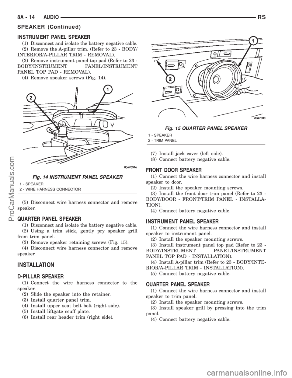
(4) Remove speaker screws (Fig. 14).
(5) Disconnect wire harness connector and remove
speaker.
QUARTER PANEL SPEAKER
(1)Disconnect and isolate the battery negative cable.
(2) Using a trim stick, gently pry speaker grill
from trim panel.
(3) Remove speaker retaining screws (Fig. 15).
(4) Disconnect wire harness connector and remove
speaker.
INSTALLATION
D-PILLAR SPEAKER
(1) Connect the wire harness connector to the
speaker.
(2) Slide the speaker into the retainer.
(3) Install quarter panel trim.
(4) Install upper seat belt bolt (right side).
(5) Install liftgate scuff plate.
(6) Install rear header trim (right side).(7) Install jack cover (left side).
(8) Connect battery negative cable.
FRONT DOOR SPEAKER
(1) Connect the wire harness connector and install
speaker to door.
(2) Install the speaker mounting screws.
(3) Install the front door trim panel (Refer to 23 -
BODY/DOOR - FRONT/TRIM PANEL - INSTALLA-
TION).
(4) Connect battery negative cable.
INSTRUMENT PANEL SPEAKER
(1) Connect the wire harness connector and install
speaker to instrument panel.
(2) Install the speaker mounting screws.
(3) Install instrument panel top pad (Refer to 23 -
BODY/INSTRUMENT PANEL/INSTRUMENT
PANEL TOP PAD - INSTALLATION).
(4) Install A-pillar trim (Refer to 23 - BODY/INTE-
RIOR/A-PILLAR TRIM - INSTALLATION).
(5) Connect battery negative cable.
QUARTER PANEL SPEAKER
(1) Connect the wire harness connector and install
speaker to trim panel.
(2) Install the speaker mounting screws.
(3) Install speaker grill by pressing into the trim
panel.
(4) Connect battery negative cable.
Fig. 14 INSTRUMENT PANEL SPEAKER
1 - SPEAKER
2 - WIRE HARNESS CONNECTOR
Fig. 15 QUARTER PANEL SPEAKER
1 - SPEAKER
2 - TRIM PANEL
8A - 14 AUDIORS
SPEAKER (Continued)
ProCarManuals.com
Page 337 of 2399

²If hazard warning signals are pulsing, no chime
will sound.
²If speed drops below 24 km/h (15 mph) before
the warning is issued, the warning will not be issued
and the distance counter will be reset.
²If turn signal lamps are not working properly,
the chime will not sound.
²When using the scan tool, refer to the proper
Body Diagnostic Manual for the procedure.
DIAGNOSIS AND TESTING - WARNING LAMP
ANNOUNCEMENT CHIME
The warning lamp announcement chime will warn
the driver to scan the instrument cluster to observe
which warning lamp is illuminated. Whenever the
volts, low fuel, airbag, door ajar or gate ajar lampsare first illuminated, the chime will sound one tone.
The door/liftgate ajar warning lamp announcement
chime sounds only if the vehicle speed is above 4
m.p.h.
Two seconds after ignition switch is turned ON or
until the seat belt warning chime ends, all warning
announcement chimes will be consolidated into one
warning announcement. This will occur 2 seconds
after the seat belt warning chime ends. If a warning
announcement should occur while another warning
chime in progress (turn signal, low oil pressure or
high speed warnings), no additional chimes will
sound after the chime in progress ends. All associ-
ated lamps will be illuminated, and the active chime
will be the warning announcement.
8B - 4 CHIME/BUZZERRS
CHIME/BUZZER (Continued)
ProCarManuals.com
Page 338 of 2399

ELECTRONIC CONTROL MODULES
TABLE OF CONTENTS
page page
ELECTRONIC CONTROL MODULES
STANDARD PROCEDURE - PCM/SKIM
PROGRAMMING.......................2
ADJUSTABLE PEDAL MODULE
DIAGNOSIS AND TESTING - ADJUSTABLE
PEDAL MODULE.......................3
REMOVAL.............................3
INSTALLATION..........................3
BODY CONTROL MODULE
DESCRIPTION..........................3
OPERATION............................3
REMOVAL.............................5
INSTALLATION..........................5
CONTROLLER ANTILOCK BRAKE
DESCRIPTION..........................5
OPERATION............................5
REMOVAL.............................6
INSTALLATION..........................6
DATA LINK CONNECTOR
DESCRIPTION..........................7
OPERATION............................7
FRONT CONTROL MODULE
DESCRIPTION..........................7
OPERATION............................7
DIAGNOSIS AND TESTING - FRONT
CONTROL MODULE....................8
REMOVAL.............................8
INSTALLATION..........................8
HEATED SEAT MODULE
DESCRIPTION..........................9
OPERATION............................9
DIAGNOSIS AND TESTING - HEATED SEAT
MODULE.............................9
REMOVAL.............................10
INSTALLATION.........................10
POWER LIFTGATE MODULE
DESCRIPTION.........................10
OPERATION...........................10
REMOVAL.............................10
INSTALLATION.........................11
POWERTRAIN CONTROL MODULE
DESCRIPTION
DESCRIPTION........................11DIAGNOSTIC TROUBLE CODE...........13
OPERATION - SENSOR RETURN - PCM
INPUT..............................25
OPERATION - SCI RECEIVE - PCM INPUT . . 25
OPERATION - IGNITION SENSE - PCM
INPUT..............................25
OPERATION - PCM GROUND............25
OPERATION
OPERATION - 8-VOLT SUPPLY - PCM
OUTPUT............................25
OPERATION - 5 VOLT SUPPLY - PCM
OUTPUT............................25
STANDARD PROCEDURE - OBTAINING
DIAGNOSTIC TROUBLE CODES..........25
REMOVAL.............................26
INSTALLATION.........................26
SENTRY KEY IMMOBILIZER MODULE
DESCRIPTION.........................26
OPERATION...........................27
REMOVAL.............................27
INSTALLATION.........................27
TRANSMISSION CONTROL MODULE
DESCRIPTION.........................28
OPERATION...........................28
STANDARD PROCEDURE
STANDARD PROCEDURE - PINION
FACTOR SETTING.....................31
STANDARD PROCEDURE - QUICK LEARN
PROCEDURE........................31
REMOVAL.............................31
INSTALLATION.........................32
MEMORY SEAT/MIRROR MODULE
DESCRIPTION.........................33
OPERATION...........................33
DIAGNOSIS AND TESTING - MEMORY
SEAT/MIRROR MODULE................33
REMOVAL.............................33
INSTALLATION.........................33
SLIDING DOOR CONTROL MODULE
DESCRIPTION.........................33
OPERATION...........................34
REMOVAL.............................34
INSTALLATION.........................34
RSELECTRONIC CONTROL MODULES8E-1
ProCarManuals.com
Page 340 of 2399

(5) Obtain ignition keys to be programmed from
customer (8 keys maximum).
(6) Using the DRB III, erase all ignition keys by
selecting MISCELLANEOUS and ERASE ALL CUR-
RENT IGN. KEYS.
(7) Program all ignition keys.
Learned Key In Ignition - Ignition key transponder
ID is currently programmed in SKIM memory.
ADJUSTABLE PEDAL MODULE
DIAGNOSIS AND TESTING - ADJUSTABLE
PEDAL MODULE
Refer to Appropriate Diagnostic Information.
REMOVAL
(1) Remove adjustable pedal assembly from vehi-
cle. (Refer to 5 - BRAKES/HYDRAULIC/MECHANI-
CAL/PEDAL - REMOVAL)
(2) Disconnect 2 wiring connectors from module
(Fig. 1).
(3) Remove cable from routing clips on module
(Fig. 1).
(4) Remove module mounting screws.
(5) Remove module.
INSTALLATION
(1) Install module on pedal assembly and install
mounting screws.
(2) Place cable in routing clips on module (Fig. 1).
(3) Connect 2 wiring connectors to module (Fig. 1).(4) Install adjustable pedal assembly. (Refer to 5 -
BRAKES/HYDRAULIC/MECHANICAL/PEDAL -
INSTALLATION)
BODY CONTROL MODULE
DESCRIPTION
The Body Control Module (BCM) is located in the
passenger compartment, attached to the bulkhead
underneath the left side of the instrument panel.
The BCM utilizes integrated circuitry and informa-
tion carried on the Programmable Communications
Interface (PCI) data bus network along with many
hard wired inputs to monitor many sensor and
switch inputs throughout the vehicle. In response to
those inputs, the internal circuitry and programming
of the BCM allow it to control and integrate many
electronic functions and features of the vehicle
through both hard wired outputs and the transmis-
sion of electronic message outputs to other electronic
modules in the vehicle over the PCI data bus.
OPERATION
The Body Control Module (BCM) supplies vehicle
occupants with visual and audible information and
controls various vehicle functions. To provide and
receive information, the BCM is interfaced to the
vehicle's serial bus communications network, referred
to as the Programmable Communications Interface
(PCI) bus.
This network consists of the;
²Powertrain Control Module (PCM)
²Transmission Control Module (TCM)
²Mechanical Instrument Cluster (MIC)
²Occupant Restraint Controller (ORC)
²Compass/Mini-Trip Computer (CMTC)
²Electronic Vehicle Information Center (EVIC)
²Controller Antilock Brake (CAB)
²HVAC Control Module
²Sliding Door Control Modules (driver and pas-
senger side doors)
²Power Liftgate Module (PLG)
²Audio system equipped with RAZ, RBU, RBK,
and RBB radios.
²Side Impact Airbag Control Module (SIACM)
²Memory Seat Module (MSM)
²Sentry Key Immobilizer Module (SKIM)
The BCM is operational when battery power is
supplied to the module.
The BCM provides the following features:
²Power Door Locks
²Automatic Door Locks
²Battery Protection - The BCM will automatically
turn off all exterior lamps after 3 minutes, and all
Fig. 1 Adjustable Pedal Module
1 - CABLE
2 - ADJUSTABLE PEDAL MODULE
3 - WIRING CONNECTORS
4 - ADJUSTABLE PEDAL ASSEMBLY
RSELECTRONIC CONTROL MODULES8E-3
ELECTRONIC CONTROL MODULES (Continued)
ProCarManuals.com
Page 341 of 2399

interior lamps after 15 minutes after the ignition is
turned off, if they are not turned off by the driver.
²Chime Driver
²Compass/Mini-Trip support.
²Interior Lighting (Courtesy/Reading Lamps)
²BCM Diagnostic Reporting
²Electronic Liftgate Release (with Power Door
Locks)
²Exterior Lighting
²Headlamp Time Delay (with/without Automatic
Headlamps)
²Illuminated Entry
²Fade to Off Interior Lamps - This feature dims
the interior lighting (courtesy lamps) gradually if theBCM does not receive any new inputs that would
cause the interior lamps to remain on.
²Pulse Width Modulated Instrument Panel Dim-
ming
²Door Lock Inhibit - This feature disables the
door lock functions if the key is in the ignition and
either front door is ajar. Pressing the Remote Keyless
Entry (RKE) lock/unlock button under these condi-
tions result in normal lock/unlock activation.
The BCM has the ability to LEARN additional fea-
tures in the vehicle, provided the appropriate switch
input and PCI data bus messages are received. Refer
to the LEARNED FEATURES table.
LEARNED FEATURES
FEATURE LEARNING KEY
CENTRAL LOCKING (WITH VTSS ONLY) DRIVER/PASSENGER KEY CYLINDER SWITCH
PRESENT
AUTOMATIC HEADLAMPS PCI MESSAGE FROM OVERHEAD OR HEADLAMP
SWITCH POSITION (AUTO)
REMOTE KEYLESS ENTRY RKE MESSAGE RECEIVED FROM MODULE
FRONT FOG LAMPS HEADLAMP SWITCH POSITION (PARK W/FRONT
FOG LAMPS)
POWER SLIDING DOOR PCI IFR RECEIVED FROM MODULE
THE BCM HAS FOUR SWITCH INPUTS FOR THE POWER SLIDING DOOR FEATURE; LOCATED IN THE
OVERHEAD CONSOLE ARE THE LEFT AND RIGHT SIDE SLIDING DOOR SWITCHES TO ACTIVATE EITHER
OR BOTH SLIDING DOORS UNDER THE PROPER CONDITIONS. ALSO ARE B-PILLAR SWITCHES LOCATED
ON THE LEFT AND RIGHT B-PILLAR POSTS.
POWER LIFTGATE PCI IFR RECEIVED FROM MODULE
THE BCM HAS ONE LIFTGATE INPUT LOCATED IN THE OVERHEAD CONSOLE.
POWER LOCKOUT SWITCH INPUT
THE BCM HAS ONE LOCKOUT SWITCH INPUT THAT WHEN ENABLED WILL DISABLE THE B-PILLAR
SLIDING DOOR SWITCHES FROM ACTIVATING EITHER SLIDING DOOR WHEN DEPRESSED.
PCI AUDIO SYSTEM PCI MESSAGE RECEIVED FROM MODULE
NOTE: SWAPPING OUT A HIGHLINE RADIO FOR A NON-PCI BUS RADIO (RAS) WILL RESULT IN IMPROPER
HARDWIRE COMMUNICATION BETWEEN THE BCM AND THE NEW RAS RADIO. THE LCD DISPLAY WILL
NOT ILLUMINATE PROPERLY DUE TO THE BCM LEARNING THAT A PCI RADIO EXISTS. HOWEVER, THE
BCM CAN RE-INITIALIZE LEARNED FEATURES VIA THE USE OF THE DRB IIITSCAN TOOL.
REMOTE RADIO CONTROLS REMOTE RADIO SWITCHES PRESENT
VEHICLE THEFT SECURITY DRIVER/PASSENGER DOOR CYLINDER LOCK
SWITCH
MEMORY SEAT AND MIRRORS MEMORY SEAT SWITCH PRESENT AND OR PCI
MESSAGE RECEIVED FROM MEMORY MODULE
ABS W/TRACTION CONTROL PCI MESSAGE RECEIVED FROM CAB
SENTRY KEY IMMOBILIZER SYSTEM PCI MESSAGE RECEIVED FROM SKIM OR VTSS
PRESENT
ADJUSTABLE PEDAL MODULE PCI MESSAGE RECEIVED FROM ADJUSTABLE
PEDAL MODULE (APM)
8E - 4 ELECTRONIC CONTROL MODULESRS
BODY CONTROL MODULE (Continued)
ProCarManuals.com
Page 342 of 2399
When replacing a BCM there are three modules
available:
²Base
²Midline
²Highline
The Midline controller is used on vehicles that
have Power Door Locks and the Highline controller is
used for vehicles equipped with a Power Liftgate. If a
vehicle is equipped with the Vehicle Theft Security
System, the Midline/Highline controller becomes a
Premium when the theft feature is enabled.
CAUTION: Do not swap Body Control Modules
between vehicles or body controller's off the shelf.
The BCM has internal diagnostic capability that
assists in diagnosing the system error. When an
OPEN or a SHORT circuit exists, the diagnostic tool
can be used to read the BCM faults. The faults are
very descriptive in identifying the appropriate fea-
ture that has faulted.
The only two faults that the BCM logs that con-
clude the replacement of a BCM are faults;
²# 01 - Internal BCM failure (replace BCM)
²# 1F - J1850 Internal Hardware Failure (replace
BCM)
Otherwise the appropriate diagnostic procedures
for each of the features should be taken when the
BCM logs a fault.
REMOVAL
(1) Disconnect and isolate the battery negative
cable.
(2) Remove the lower instrument panel silencer.
(3) Remove the knee blocker and reinforcement
(Refer to 23 - BODY/INSTRUMENT PANEL/KNEE
BLOCKER REINFORCEMENT - REMOVAL).
(4) Disconnect the five wire connectors from the
bottom of the Body Control Module (BCM).
(5) Move bulkhead wiring aside.
(6) Remove the screws holding the BCM to the
bulkhead.
(7) Remove the BCM from the mounting bracket.
INSTALLATION
(1) Install the BCM to the mounting bracket.
(2) Install the screws holding the BCM to the
bulkhead.
(3) Connect the five wire connectors to the bottom
of the Body Control Module (BCM).
(4) Install the knee blocker and reinforcement
(Refer to 23 - BODY/INSTRUMENT PANEL/KNEE
BLOCKER REINFORCEMENT - INSTALLATION).
(5) Install the lower instrument panel silencer.
(6) Connect the battery negative cable.
(7) Verify proper operation of BCM and its func-
tions.
CONTROLLER ANTILOCK
BRAKE
DESCRIPTION
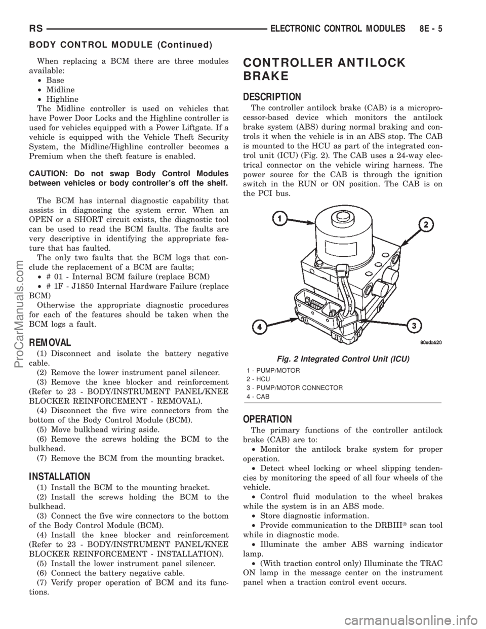
The controller antilock brake (CAB) is a micropro-
cessor-based device which monitors the antilock
brake system (ABS) during normal braking and con-
trols it when the vehicle is in an ABS stop. The CAB
is mounted to the HCU as part of the integrated con-
trol unit (ICU) (Fig. 2). The CAB uses a 24-way elec-
trical connector on the vehicle wiring harness. The
power source for the CAB is through the ignition
switch in the RUN or ON position. The CAB is on
the PCI bus.
OPERATION
The primary functions of the controller antilock
brake (CAB) are to:
²Monitor the antilock brake system for proper
operation.
²Detect wheel locking or wheel slipping tenden-
cies by monitoring the speed of all four wheels of the
vehicle.
²Control fluid modulation to the wheel brakes
while the system is in an ABS mode.
²Store diagnostic information.
²Provide communication to the DRBIIItscan tool
while in diagnostic mode.
²Illuminate the amber ABS warning indicator
lamp.
²(With traction control only) Illuminate the TRAC
ON lamp in the message center on the instrument
panel when a traction control event occurs.
Fig. 2 Integrated Control Unit (ICU)
1 - PUMP/MOTOR
2 - HCU
3 - PUMP/MOTOR CONNECTOR
4 - CAB
RSELECTRONIC CONTROL MODULES8E-5
BODY CONTROL MODULE (Continued)
ProCarManuals.com