2002 CHRYSLER TOWN AND COUNTRY air filter housing
[x] Cancel search: air filter housingPage 305 of 2399

STANDARD PROCEDURE
STANDARD PROCEDURE - COOLANT SERVICE
For engine coolant recommended service schedule,
(Refer to LUBRICATION & MAINTENANCE/MAIN-
TENANCE SCHEDULES - DESCRIPTION).
STANDARD PROCEDURE - ADDING
ADDITIONAL COOLANT
The pressure/vent cap should not be removed
from the coolant recovery pressure container
when the engine is hot.When additional coolant is
needed to maintain this level, it should be added to
the coolant recovery pressure container (Fig. 1). Use
only 50/50 mix of ethylene glycol type antifreeze and
distilled water. For the recommeded antifreeze/cool-
ant type (Refer to LUBRICATION & MAINTE-
NANCE/FLUID TYPES - DESCRIPTION).
CAUTION: Do not use well water, or suspect water
supply in cooling system. A 50/50 ethylene glycol
and distilled water mix is recommended. For the
recommeded antifreeze/coolant type (Refer to
LUBRICATION & MAINTENANCE/FLUID TYPES -
DESCRIPTION).
STANDARD PROCEDURE - COOLANT LEVEL
CHECK
NOTE: Do not remove pressure/vent cap for routine
coolant level inspections.
The coolant reserve system provides a quick visual
method for determining the coolant level without
removing the pressure/vent cap.With the engine
cold and not running,simply observe the level of
the coolant in the coolant recovery pressure container
(Fig. 2). The coolant level should be between the MIN
and MAX marks.
STANDARD PROCEDURE - COOLING SYSTEM
FILLING
(1) Remove pressure vent cap from coolant recov-
ery pressure container.
(2) Loosen air bleed screw on the thermostat hous-
ing (Fig. 9).
(3) Slowly fill the cooling through the coolant
recovery pressure container until a steady stream of
coolant comes out of the air bleed.
(4) Tighten the air bleed screw.
Fig. 1 UNDERHOOD FLUID FILL LOCATIONS
1 - COOLANT PRESSURE/VENT CAP
2 - BRAKE MASTER CYLINDER
3 - INTELLIGENT POWER MODULE
4 - BATTERY
5 - COOLANT RECOVERY PRESSURE CONTAINER6 - OIL DIPSTICK
7 - WINDSHIELD SOLVENT RESEVOIR
8 - AIR FILTER HOUSING
9 - ENGINE OIL FILL CAP
7a - 16 ENGINERG
ProCarManuals.com
Page 1225 of 2399
AIR CLEANER ELEMENT
REMOVAL
(1) Unsnap 2 clips.
(2) Lift cover and pull toward the engine and
remove cover tabs from air box.
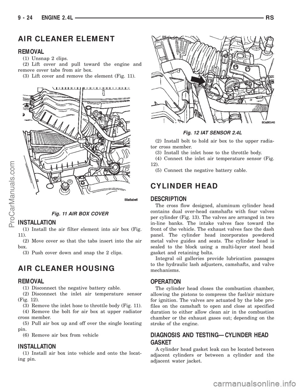
(3) Lift cover and remove the element (Fig. 11).
INSTALLATION
(1) Install the air filter element into air box (Fig.
11).
(2) Move cover so that the tabs insert into the air
box.
(3) Push cover down and snap the 2 clips.
AIR CLEANER HOUSING
REMOVAL
(1) Disconnect the negative battery cable.
(2) Disconnect the inlet air temperature sensor
(Fig. 12).
(3) Remove the inlet hose to throttle body (Fig. 11).
(4) Remove the bolt for air box at upper radiator
cross member.
(5) Pull air box up and off over the single locating
pin.
(6) Remove air box from vehicle
INSTALLATION
(1) Install air box into vehicle and onto the locat-
ing pin.(2) Install bolt to hold air box to the upper radia-
tor cross member.
(3) Install the inlet hose to the throttle body.
(4) Connect the inlet air temperature sensor (Fig.
12).
(5) Connect the negative battery cable.
CYLINDER HEAD
DESCRIPTION
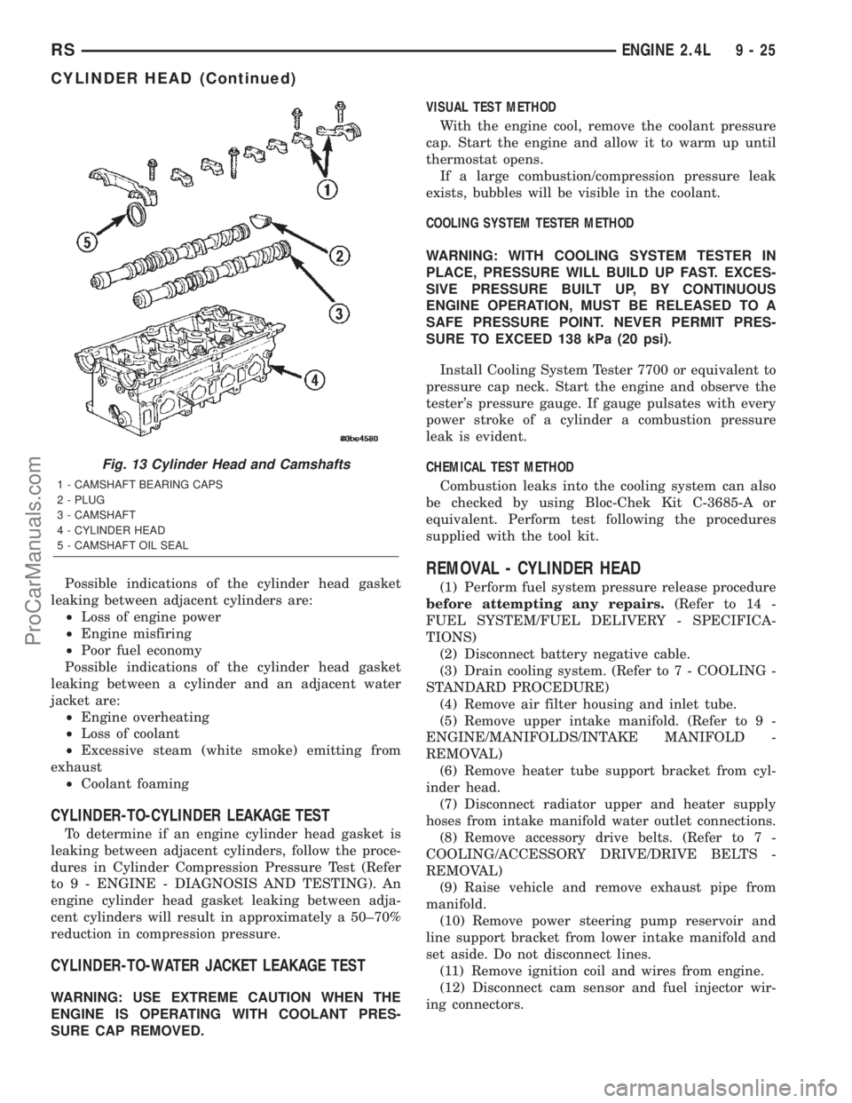
The cross flow designed, aluminum cylinder head
contains dual over-head camshafts with four valves
per cylinder (Fig. 13). The valves are arranged in two
in-line banks. The intake valves face toward the
front of the vehicle. The exhaust valves face the dash
panel. The cylinder head incorporates powdered
metal valve guides and seats. The cylinder head is
sealed to the block using a multi-layer steel head
gasket and retaining bolts.
Integral oil galleries provide lubrication passages
to the hydraulic lash adjusters, camshafts, and valve
mechanisms.
OPERATION
The cylinder head closes the combustion chamber,
allowing the pistons to compress the fuel/air mixture
for ignition. The valves are actuated by the lobe pro-
files on the camshaft to open and close at specified
duration to either allow clean air in the combustion
chamber or the exhaust gases out; depending on the
stroke of the engine.
DIAGNOSIS AND TESTINGÐCYLINDER HEAD
GASKET
A cylinder head gasket leak can be located between
adjacent cylinders or between a cylinder and the
adjacent water jacket.
Fig. 11 AIR BOX COVER
Fig. 12 IAT SENSOR 2.4L
9 - 24 ENGINE 2.4LRS
ProCarManuals.com
Page 1226 of 2399
Possible indications of the cylinder head gasket
leaking between adjacent cylinders are:
²Loss of engine power
²Engine misfiring
²Poor fuel economy
Possible indications of the cylinder head gasket
leaking between a cylinder and an adjacent water
jacket are:
²Engine overheating
²Loss of coolant
²Excessive steam (white smoke) emitting from
exhaust
²Coolant foaming
CYLINDER-TO-CYLINDER LEAKAGE TEST
To determine if an engine cylinder head gasket is
leaking between adjacent cylinders, follow the proce-
dures in Cylinder Compression Pressure Test (Refer
to 9 - ENGINE - DIAGNOSIS AND TESTING). An
engine cylinder head gasket leaking between adja-
cent cylinders will result in approximately a 50±70%
reduction in compression pressure.
CYLINDER-TO-WATER JACKET LEAKAGE TEST
WARNING: USE EXTREME CAUTION WHEN THE
ENGINE IS OPERATING WITH COOLANT PRES-
SURE CAP REMOVED.VISUAL TEST METHOD
With the engine cool, remove the coolant pressure
cap. Start the engine and allow it to warm up until
thermostat opens.
If a large combustion/compression pressure leak
exists, bubbles will be visible in the coolant.
COOLING SYSTEM TESTER METHOD
WARNING: WITH COOLING SYSTEM TESTER IN
PLACE, PRESSURE WILL BUILD UP FAST. EXCES-
SIVE PRESSURE BUILT UP, BY CONTINUOUS
ENGINE OPERATION, MUST BE RELEASED TO A
SAFE PRESSURE POINT. NEVER PERMIT PRES-
SURE TO EXCEED 138 kPa (20 psi).
Install Cooling System Tester 7700 or equivalent to
pressure cap neck. Start the engine and observe the
tester's pressure gauge. If gauge pulsates with every
power stroke of a cylinder a combustion pressure
leak is evident.
CHEMICAL TEST METHOD
Combustion leaks into the cooling system can also
be checked by using Bloc-Chek Kit C-3685-A or
equivalent. Perform test following the procedures
supplied with the tool kit.
REMOVAL - CYLINDER HEAD
(1) Perform fuel system pressure release procedure
before attempting any repairs.(Refer to 14 -
FUEL SYSTEM/FUEL DELIVERY - SPECIFICA-
TIONS)
(2) Disconnect battery negative cable.
(3) Drain cooling system. (Refer to 7 - COOLING -
STANDARD PROCEDURE)
(4) Remove air filter housing and inlet tube.
(5) Remove upper intake manifold. (Refer to 9 -
ENGINE/MANIFOLDS/INTAKE MANIFOLD -
REMOVAL)
(6) Remove heater tube support bracket from cyl-
inder head.
(7) Disconnect radiator upper and heater supply
hoses from intake manifold water outlet connections.
(8) Remove accessory drive belts. (Refer to 7 -
COOLING/ACCESSORY DRIVE/DRIVE BELTS -
REMOVAL)
(9) Raise vehicle and remove exhaust pipe from
manifold.
(10) Remove power steering pump reservoir and
line support bracket from lower intake manifold and
set aside. Do not disconnect lines.
(11) Remove ignition coil and wires from engine.
(12) Disconnect cam sensor and fuel injector wir-
ing connectors.
Fig. 13 Cylinder Head and Camshafts
1 - CAMSHAFT BEARING CAPS
2 - PLUG
3 - CAMSHAFT
4 - CYLINDER HEAD
5 - CAMSHAFT OIL SEAL
RSENGINE 2.4L9-25
CYLINDER HEAD (Continued)
ProCarManuals.com
Page 1300 of 2399
AIR CLEANER ELEMENT
REMOVAL
(1) Unsnap 2 clips.
(2) Lift cover and pull toward the engine and
remove cover tabs from air box.
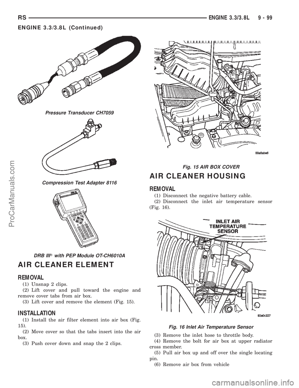
(3) Lift cover and remove the element (Fig. 15).
INSTALLATION
(1) Install the air filter element into air box (Fig.
15).
(2) Move cover so that the tabs insert into the air
box.
(3) Push cover down and snap the 2 clips.
AIR CLEANER HOUSING
REMOVAL
(1) Disconnect the negative battery cable.
(2) Disconnect the inlet air temperature sensor
(Fig. 16).
(3) Remove the inlet hose to throttle body.
(4) Remove the bolt for air box at upper radiator
cross member.
(5) Pull air box up and off over the single locating
pin.
(6) Remove air box from vehicle
Pressure Transducer CH7059
Compression Test Adapter 8116
DRB IIITwith PEP Module OT-CH6010A
Fig. 15 AIR BOX COVER
Fig. 16 Inlet Air Temperature Sensor
RSENGINE 3.3/3.8L9-99
ENGINE 3.3/3.8L (Continued)
ProCarManuals.com
Page 1338 of 2399
RIGHT MOUNT
REMOVAL
(1) Remove air cleaner housing lid and clean air
hose from throttle body.
(2) Remove air cleaner element and housing.
(3) Disconnect make-up air hose from cylinder
head cover.
(4) Remove the load on the right engine mount by
carefully supporting the engine assembly with a floor
jack.
(5) Disconnect electrical harness support clips from
engine mount bracket.
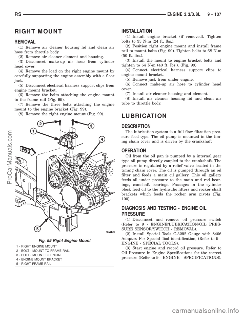
(6) Remove the bolts attaching the engine mount
to the frame rail (Fig. 99).
(7) Remove the three bolts attaching the engine
mount to the engine bracket (Fig. 99).
(8) Remove the right engine mount (Fig. 99).
INSTALLATION
(1) Install engine bracket (if removed). Tighten
bolts to 33 N´m (24 ft. lbs.).
(2) Position right engine mount and install frame
rail to mount bolts (Fig. 99). Tighten bolts to 68 N´m
(50 ft. lbs.).
(3) Install the mount to engine bracket bolts and
tighten to 54 N´m (40 ft. lbs.). (Fig. 99)
(4) Connect electrical harness support clips to
engine mount bracket.
(5) Remove jack from under engine.
(6) Connect make-up air hose to cylinder head
cover.
(7) Install air cleaner housing and element.
(8) Install air cleaner housing lid and clean air
tube to throttle body.
LUBRICATION
DESCRIPTION
The lubrication system is a full flow filtration pres-
sure feed type. The oil pump is mounted in the tim-
ing chain cover and is driven by the crankshaft
OPERATION
Oil from the oil pan is pumped by a internal gear
type oil pump directly coupled to the crankshaft. The
pressure is regulated by a relief valve located in the
timing chain cover. The oil is pumped through an oil
filter and feeds a main oil gallery. This oil gallery
feeds oil under pressure to the main and rod bear-
ings, camshaft bearings. Passages in the cylinder
block feed oil to the hydraulic lifters and rocker shaft
brackets which feeds the rocker arm pivots (Fig.
100).
DIAGNOSIS AND TESTING - ENGINE OIL
PRESSURE
(1) Disconnect and remove oil pressure switch
(Refer to 9 - ENGINE/LUBRICATION/OIL PRES-
SURE SENSOR/SWITCH - REMOVAL).
(2) Install Special Tools C-3292 Gauge with 8406
Adaptor. For Special Tool identification, (Refer to 9 -
ENGINE - SPECIAL TOOLS).
(3) Start engine and record oil pressure. Refer to
Oil Pressure in Engine Specifications for the correct
pressure (Refer to 9 - ENGINE - SPECIFICATIONS).
Fig. 99 Right Engine Mount
1 - RIGHT ENGINE MOUNT
2 - BOLT - MOUNT TO FRAME RAIL
3 - BOLT - MOUNT TO ENGINE
4 - ENGINE MOUNT BRACKET
5 - RIGHT FRAME RAIL
RSENGINE 3.3/3.8L9 - 137
ProCarManuals.com
Page 1435 of 2399
TURBOCHARGER SYSTEM
DESCRIPTION
CAUTION: The turbocharger is a performance part
and must not be tampered with. The wastegate
bracket is an integral part of the turbocharger. Tam-
pering with the wastegate components can reduce
durability by increasing cylinder pressure and ther-
mal loading due to incorrect inlet and exhaust man-
ifold pressure. Poor fuel economy and failure to
meet regulatory emissions laws may result. Increas-
ing the turbocharger boost WILL NOT increase
engine power.
The turbocharger is an exhaust-driven super-
charger which increases the pressure and density of
the air entering the engine. With the increase of air
entering the engine, more fuel can be injected into
the cylinders, which creates more power during com-
bustion.
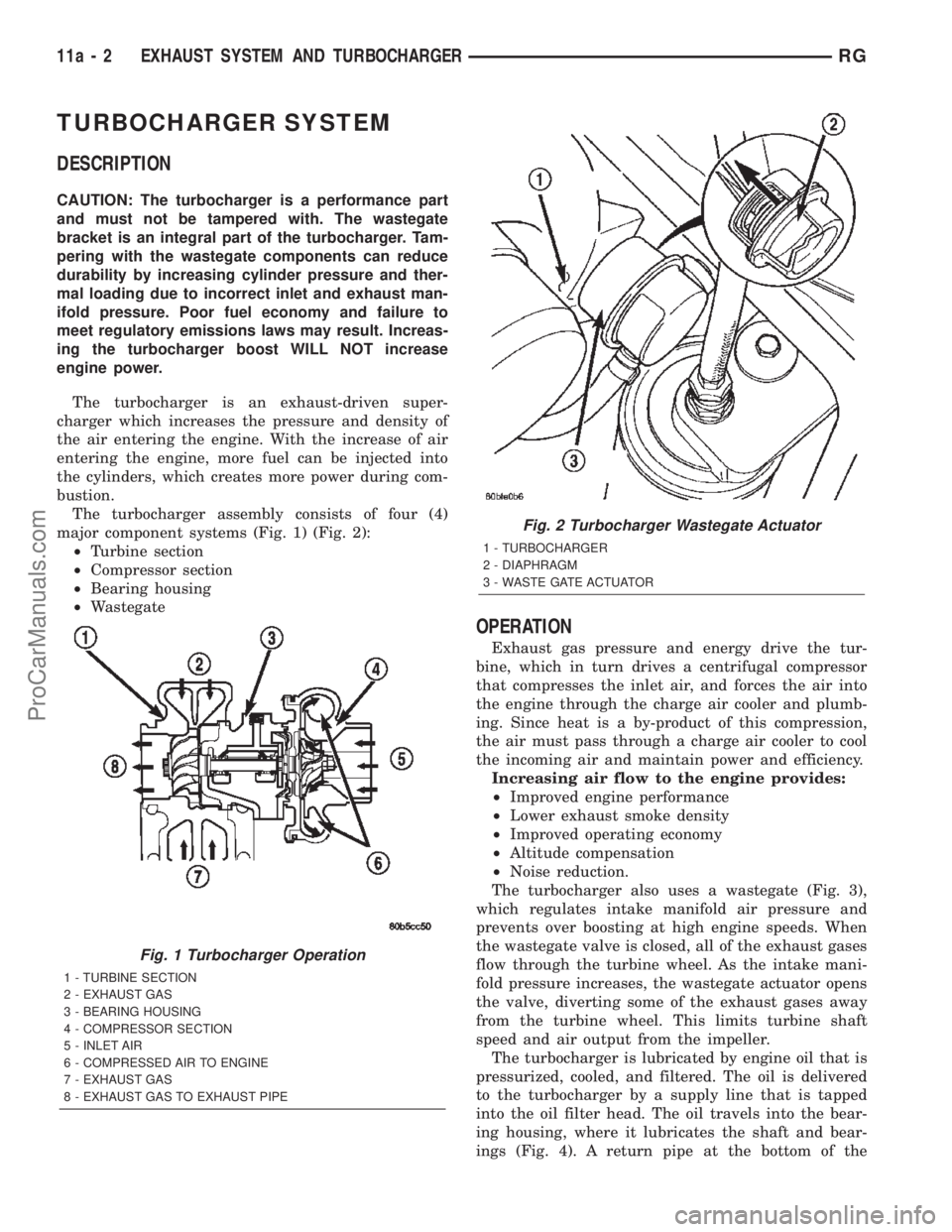
The turbocharger assembly consists of four (4)
major component systems (Fig. 1) (Fig. 2):
²Turbine section
²Compressor section
²Bearing housing
²Wastegate
OPERATION
Exhaust gas pressure and energy drive the tur-
bine, which in turn drives a centrifugal compressor
that compresses the inlet air, and forces the air into
the engine through the charge air cooler and plumb-
ing. Since heat is a by-product of this compression,
the air must pass through a charge air cooler to cool
the incoming air and maintain power and efficiency.
Increasing air flow to the engine provides:
²Improved engine performance
²Lower exhaust smoke density
²Improved operating economy
²Altitude compensation
²Noise reduction.
The turbocharger also uses a wastegate (Fig. 3),
which regulates intake manifold air pressure and
prevents over boosting at high engine speeds. When
the wastegate valve is closed, all of the exhaust gases
flow through the turbine wheel. As the intake mani-
fold pressure increases, the wastegate actuator opens
the valve, diverting some of the exhaust gases away
from the turbine wheel. This limits turbine shaft
speed and air output from the impeller.
The turbocharger is lubricated by engine oil that is
pressurized, cooled, and filtered. The oil is delivered
to the turbocharger by a supply line that is tapped
into the oil filter head. The oil travels into the bear-
ing housing, where it lubricates the shaft and bear-
ings (Fig. 4). A return pipe at the bottom of the
Fig. 1 Turbocharger Operation
1 - TURBINE SECTION
2 - EXHAUST GAS
3 - BEARING HOUSING
4 - COMPRESSOR SECTION
5 - INLET AIR
6 - COMPRESSED AIR TO ENGINE
7 - EXHAUST GAS
8 - EXHAUST GAS TO EXHAUST PIPE
Fig. 2 Turbocharger Wastegate Actuator
1 - TURBOCHARGER
2 - DIAPHRAGM
3 - WASTE GATE ACTUATOR
11a - 2 EXHAUST SYSTEM AND TURBOCHARGERRG
ProCarManuals.com
Page 1488 of 2399
FUEL SYSTEM
TABLE OF CONTENTS
page page
FUEL SYSTEM 2.5L TURBO DIESEL
DESCRIPTION - DIESEL FUEL DELIVERY
SYSTEM.............................1
WARNING - HIGH FUEL SYSTEM PRESSURE . . 1
DIAGNOSIS AND TESTING
DIAGNOSIS AND TESTING - AIR IN FUEL
SYSTEM.............................1
DIAGNOSIS AND TESTING - FUEL SUPPLY
RESTRICTIONS........................1
STANDARD PROCEDURE
STANDARD PROCEDURES - DRAINING
WATER FROM FUEL FILTER..............2STANDARD PROCEDURE - FUEL SYSTEM
AIR PURGE...........................2
STANDARD PROCEDURES - CLEANING
FUEL SYSTEM COMPONENTS............2
SPECIFICATIONS - TORQUE...............3
FUEL DELIVERY..........................4
FUEL INJECTION........................11
FUEL SYSTEM 2.5L TURBO
DIESEL
DESCRIPTION - DIESEL FUEL DELIVERY
SYSTEM
The fuel system on the 2.5L Common Rail Diesel
Engine uses a fuel injection pump and an Electronic
Control Module (ECM).
The fuel delivery system consists of the:
²Accelerator pedal
²Air cleaner housing/element
²Fuel filter/water separator
²Fuel heater
²Fuel heater relay
²Fuel transfer (lift) pump
²Fuel injection pump
²Fuel injectors
²Fuel tank
²Fuel tank filler/vent tube assembly
²Fuel tank filler tube cap
²Fuel tank module containing the rollover valve
and a fuel gauge sending unit (fuel level sensor).
²Fuel tubes/lines/hoses
²High-pressure fuel injector lines
²Low-pressure fuel supply lines
²Low-pressure fuel return line
²Overflow valve
²Quick-connect fittings
²Water draining
WARNING - HIGH FUEL SYSTEM PRESSURE
WARNING:: THE INJECTION PUMP SUPPLIES HIGH-
PRESSURE FUEL TO EACH INDIVIDUAL INJECTOR
THROUGH HIGH-PRESSURE LINES. FUEL UNDERTHIS AMOUNT OF PRESSURE CAN PENETRATE
SKIN AND CAUSE PERSONAL INJURY. WEAR
SAFETY GOGGLES AND ADEQUATE PROTECTIVE
CLOTHING. AVOID CONTACT WITH FUEL SPRAY
WHEN BLEEDING HIGH-PRESSURE FUEL LINES.
DIAGNOSIS AND TESTING
DIAGNOSIS AND TESTING - AIR IN FUEL
SYSTEM
Air will enter the fuel system whenever fuel supply
lines, separator filters, injection pump, high-pressure
lines or injectors are removed or disconnected. Air
trapped in the fuel system can result in hard start-
ing, a rough running engine, engine misfire, low
power, excessive smoke and fuel knock. After service
is performed, air must be bled from the system
before starting the engine.
Inspect the fuel system from the fuel tank to the
injectors for loose connections. Leaking fuel is an
indicator of loose connections or defective seals. Air
can also enter the fuel system between the fuel tank
and the transfer pump. Inspect the fuel tank and fuel
lines for damage that might allow air into the sys-
tem.
DIAGNOSIS AND TESTING - FUEL SUPPLY
RESTRICTIONS
LOW-PRESSURE LINES
Fuel supply line restrictions or a defective fuel
transfer pump can cause starting problems and pre-
vent engine from accelerating. The starting problems
include; low power and/or white fog like exhaust.
RGFUEL SYSTEM14a-1
ProCarManuals.com
Page 1492 of 2399

INSTALLATION - FUEL RAIL
(1) Install fuel rail to intake manifold/cylinder
head cover (Fig. 2). Torque retaining bolts to
27.5N´m.
(2) Install engine electrical harness retainers from
the fuel rail retaining bolts/studs. (Fig. 2)
(3) Connect fuel rail high pressure sensor electri-
cal connector. (Fig. 2)
(4) Connect fuel rail return line. (Fig. 2)
(5) Connect fuel rail supply line. (Fig. 2)
(6) Connect fuel injector high pressure lines. (Fig.
2)
(7) Install engine cover (Refer to 9 - ENGINE -
INSTALLATION).
(8) Connect negative battery cable.
FUEL FILTER / WATER
SEPARATOR
DESCRIPTION
The fuel filter/water separator assembly is located
under the vehicle in front of the rear axle assembly
(Fig. 3). The assembly also includes the fuel heater
and Water-In-Fuel (WIF) sensor.
OPERATION
The fuel filter/water separator protects the fuel
injection pump by removing water and contaminants
from the fuel. The construction of the filter/separator
allows fuel to pass through it, but helps prevent
moisture (water) from doing so. Moisture collects at
the bottom of the canister.
Fig. 2 FUEL RAIL COMPONENTS
1 - FUEL INJECTOR RETURN LINE
2 - FUEL INJECTOR HIGH PRESSURE LINE
3 - OIL SEPARATOR
4 - FUEL INJECTOR
5 - CAMSHAFT POSITION SENSOR
6 - BOOST PRESSURE/INTAKE AIR TEMPERATURE SENSOR
7 - EGR SOLENOID
8 - FUEL PRESSURE SENSOR
9 - CYLINDER HEAD COVER/INTAKE MANIFOLD
10 - FUEL RAIL
Fig. 3 FUEL FILTER/WATER SEPARATOR
1 - LIFT PUMP RETAINING BOLTS
2 - LIFT PUMP
3 - FUEL FILTER/WATER SEPARATOR HOUSING
4 - FUEL HEATER
5 - CHECK BALL
6 - O-RING
7 - FLOW DIVERTER
8 - FUEL FILTER
9 - O-RING
10 - FUEL FILTER BOWL ASSEMBLY
RGFUEL DELIVERY14a-5
FUEL RAIL (Continued)
ProCarManuals.com