2002 CHRYSLER TOWN AND COUNTRY air filter housing
[x] Cancel search: air filter housingPage 2244 of 2399
HEATING & AIR CONDITIONING
TABLE OF CONTENTS
page page
HEATING & AIR CONDITIONING
DESCRIPTION
DESCRIPTION - SINGLE ZONE...........1
DESCRIPTION - DUAL ZONE.............1
DESCRIPTION - MANUAL THREE ZONE.....1
DESCRIPTION - THREE ZONE AUTOMATIC
TEMPERATURE CONTROL...............2
OPERATION
OPERATION - DUAL ZONE...............3
OPERATION - MANUAL THREE ZONE......3
OPERATION - THREE ZONE ATC..........4
DIAGNOSIS AND TESTING
DIAGNOSIS AND TESTING - A/C COOL
DOWN TEST..........................5DIAGNOSIS AND TESTING - A/C
PERFORMANCE TEST..................5
DIAGNOSIS AND TESTING - HEATER
PERFORMANCE TEST..................6
SPECIFICATIONS - HEATER-A/C SYSTEM.....7
CONTROLS - FRONT......................8
CONTROLS - REAR......................29
DISTRIBUTION - FRONT...................39
DISTRIBUTION - REAR....................51
PLUMBING - FRONT.....................59
PLUMBING - REAR......................97
DIESEL SUPPLEMENTAL HEATER - DCHA -
BUX.................................109
HEATING & AIR
CONDITIONING
DESCRIPTION
DESCRIPTION - SINGLE ZONE
A single zone heating and air conditioning system
allows one temperature setting for the entire vehicle.
The full range of temperatures that the system can
produce are available by rotating the temperature
control located in control panel.
The control panel and integral computer is
mounted in the instrument panel.
DESCRIPTION - DUAL ZONE
A manual Dual Zone Heating and Air Conditioning
system allows completely independent side-to-side
tempeture control of the discharge air.
The Dual Zone Heating and Air Conditioning sys-
tem includes a dust and odor air filter. The filter ele-
ment is the same size as the air conditioning
evaporator to ensure ample capacity. A door at the
base of the heating and air conditioning housing
below the glove box provides easy access to the filter
element.
The control panel and integral computer is located
in the instrument panel.
The instrument panel mounted control and inte-
gral computer contains:
²a power button which allows the system to be
completely turned off. Contains an LED that illumi-
nates to show when the function is operational.²rear window defogger on/off switch. Contains an
LED that illuminates to show when the function is
operational.
²slide controls for completely independent side-to-
side temperature control of the discharged air. The
full range of temperature that the system can pro-
duce in any mode is available on either side of the
vehicle by independently positioning the slide con-
trols on the instrument panel.
²air recirculation on/off switch. The Recirculate
button contains an LED that illuminates to show
when the function is in operation.
²air conditioning on/off switch. The Snowflake
button contains an LED that illuminates to shown
when the function is in operation.
²rotary knob for fan speed selection.
²a rotary knob for mode control.
DESCRIPTION - MANUAL THREE ZONE
The fully adjustable Three-Zone front and rear
heating and air conditioning system allows interme-
diate seat passengers the ability to regulate air tem-
perature as well as fan speed. All controls are
identified by ISO graphic symbols.
The Three Zone Heating and Air Conditioning sys-
tem includes a dust and odor air filter. The filter ele-
ment is the same size as the air conditioning
evaporator to ensure ample capacity. A door at the
base of the heating and air conditioning housing
below the glove box provides easy access to the filter
element.
RSHEATING & AIR CONDITIONING24-1
ProCarManuals.com
Page 2245 of 2399
FRONT CONTROL PANEL
The front control panel and integral computer is
mounted in the instrument panel.
The instrument panel mounted control and inte-
gral computer contains:
²a power button which allows the system to be
completely turned off.
²rear window defogger on/off switch.
²slide controls for completely independent side-to-
side temperature control of the discharge air. The full
range of temperature that the system can produce in
any mode is available on either side of the vehicle by
independently positioning the slide controls on the
instrument panel.
²air recirculation button. The Recirculate button
contains an LED that illuminates to show when the
function is in operation.
²an air conditioning button that allows the com-
pressor to be turned on/off. The Snowflake button
contains an LED that illuminates to shown when the
function is in operation.
²rotary knobs for front and rear fan speed selec-
tion.
²a rotary knob for mode control.
REAR CONTROL PANEL
A rear control panel centrally mounted on the
headliner has a rotary adjustment for temperature
and fan speed control of the rear unit by intermedi-
ate seat passengers when the front control rear knob
is set to the rear position.
DESCRIPTION - THREE ZONE AUTOMATIC
TEMPERATURE CONTROL
The Three-Zone Automatic Temperature Control
(ATC) allows occupants to select a comfort tempera-
ture, which is the perceived temperature level not
the actual passenger compartment air temperature.
The Three Zone Automatic Temperature Control
system includes a dust and odor air filter. The filter
element is the same size as the air conditioning evap-
orator to ensure ample capacity. A door at the base of
the heater and air conditioning housing below the
glove box provides easy access to the filter element.
The ATC computer utilizes integrated circuitry and
information carried on the Programmable Communi-
cations Interface (PCI) data bus network to monitor
many sensors and switch inputs throughout the vehi-
cle. In response to those inputs, the internal circuitry
and programming of the ATC computer allow it to
control electronic functions and features of the ATC
system. The inputs to the ATC computer are:
²Vehicle Speed/Engine RPM± The ATC com-
puter monitors engine RPM, vehicle speed and Man-
ifold Absolute Pressure information from the PCM.²Coolant Temperature± ATC computer moni-
tors Coolant temperature received from the PCM and
converts it to degrees Fahrenheit.
²Ambient Temperature± ATC computer moni-
tors Ambient temperature from the Compass Mini
Trip Computer (CMTC) and converts it to degrees
Fahrenheit.
²Engine Miscellaneous Sensor Status±ATC
computer monitors A/C disable information from the
PCM.
²Refrigerant Pressure± ATC computer moni-
tors Barometric Pressure, Intake Air Temperature,
High Side Pressure and Methanol Content as broad-
cast by the PCM.
²Door Ajar Status± The ATC computer moni-
tors Driver Front Door, Passenger Front Door, Left
Rear Door, Right Rear Door and Liftgate ajar infor-
mation, as identified by the Body Control Module
(BCM), to determine if all in-car temperatures should
be maintained.
²Dimming± The ATC computer monitors dim-
ming status from the BCM to determine the required
level of brightness and will dim accordingly.
²Vehicle Odometer± The ATC computer moni-
tors the vehicle odometer information from the BCM
to prevent flashing the VF tube icons if the manual
motor calibration or manual cool down tests have
failed. Flashing of the display icons will cease when
the vehicle odometer is greater than 3 miles.
²English Metric± The ATC computer monitors
the English/Metric information broadcast by the
CMTC. The set temp displays for both the front and
rear control heads will be set accordingly.
²Vehicle Identification Number± The ATC
computer monitors the last eight characters of the
VIN broadcast by the PCM and compares it to the
information stored in EEPROM. If it is different, the
new number will be stored over the old one and a
motor calibration shall be initiated.
²A/C System Information± The ATC computer
will send a message for Evaporator Temperature too
Low, Fan Blower Relay status, Evaporator Sensor
Failure, Rear Window Defogger Relay and A/C Select.
FRONT CONTROL PANEL
The front control panel and integral computer is
mounted in the instrument panel.
The instrument panel mounted control and inte-
gral computer contains:
²A power button which allows the system to be
completely turned off. The display is blank when the
system is off.
²Three rocker switches that select comfort tem-
peratures from 15É to 30É C (59É to 85É F), which are
shown in the vacuum-fluorescent digital control dis-
play. If the set temp is 59 and the down button is
24 - 2 HEATING & AIR CONDITIONINGRS
HEATING & AIR CONDITIONING (Continued)
ProCarManuals.com
Page 2254 of 2399
REMOVAL
(1) Disconnect and isolate the battery negative
cable.
(2) Disconnect the headlamp and dash wire har-
ness connector for the A/C pressure transducer from
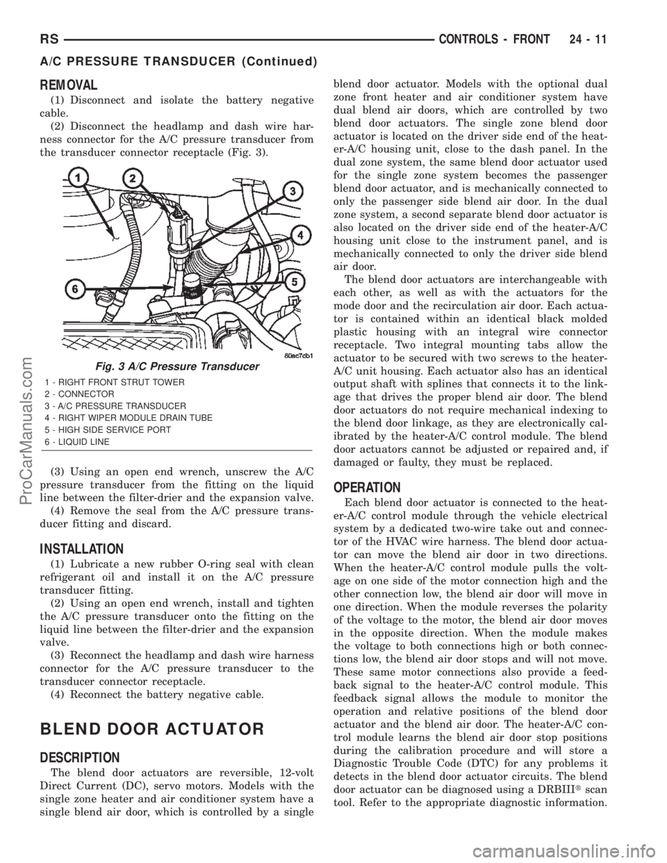
the transducer connector receptacle (Fig. 3).
(3) Using an open end wrench, unscrew the A/C
pressure transducer from the fitting on the liquid
line between the filter-drier and the expansion valve.
(4) Remove the seal from the A/C pressure trans-
ducer fitting and discard.
INSTALLATION
(1) Lubricate a new rubber O-ring seal with clean
refrigerant oil and install it on the A/C pressure
transducer fitting.
(2) Using an open end wrench, install and tighten
the A/C pressure transducer onto the fitting on the
liquid line between the filter-drier and the expansion
valve.
(3) Reconnect the headlamp and dash wire harness
connector for the A/C pressure transducer to the
transducer connector receptacle.
(4) Reconnect the battery negative cable.
BLEND DOOR ACTUATOR
DESCRIPTION
The blend door actuators are reversible, 12-volt
Direct Current (DC), servo motors. Models with the
single zone heater and air conditioner system have a
single blend air door, which is controlled by a singleblend door actuator. Models with the optional dual
zone front heater and air conditioner system have
dual blend air doors, which are controlled by two
blend door actuators. The single zone blend door
actuator is located on the driver side end of the heat-
er-A/C housing unit, close to the dash panel. In the
dual zone system, the same blend door actuator used
for the single zone system becomes the passenger
blend door actuator, and is mechanically connected to
only the passenger side blend air door. In the dual
zone system, a second separate blend door actuator is
also located on the driver side end of the heater-A/C
housing unit close to the instrument panel, and is
mechanically connected to only the driver side blend
air door.
The blend door actuators are interchangeable with
each other, as well as with the actuators for the
mode door and the recirculation air door. Each actua-
tor is contained within an identical black molded
plastic housing with an integral wire connector
receptacle. Two integral mounting tabs allow the
actuator to be secured with two screws to the heater-
A/C unit housing. Each actuator also has an identical
output shaft with splines that connects it to the link-
age that drives the proper blend air door. The blend
door actuators do not require mechanical indexing to
the blend door linkage, as they are electronically cal-
ibrated by the heater-A/C control module. The blend
door actuators cannot be adjusted or repaired and, if
damaged or faulty, they must be replaced.
OPERATION
Each blend door actuator is connected to the heat-
er-A/C control module through the vehicle electrical
system by a dedicated two-wire take out and connec-
tor of the HVAC wire harness. The blend door actua-
tor can move the blend air door in two directions.
When the heater-A/C control module pulls the volt-
age on one side of the motor connection high and the
other connection low, the blend air door will move in
one direction. When the module reverses the polarity
of the voltage to the motor, the blend air door moves
in the opposite direction. When the module makes
the voltage to both connections high or both connec-
tions low, the blend air door stops and will not move.
These same motor connections also provide a feed-
back signal to the heater-A/C control module. This
feedback signal allows the module to monitor the
operation and relative positions of the blend door
actuator and the blend air door. The heater-A/C con-
trol module learns the blend air door stop positions
during the calibration procedure and will store a
Diagnostic Trouble Code (DTC) for any problems it
detects in the blend door actuator circuits. The blend
door actuator can be diagnosed using a DRBIIItscan
tool. Refer to the appropriate diagnostic information.
Fig. 3 A/C Pressure Transducer
1 - RIGHT FRONT STRUT TOWER
2 - CONNECTOR
3 - A/C PRESSURE TRANSDUCER
4 - RIGHT WIPER MODULE DRAIN TUBE
5 - HIGH SIDE SERVICE PORT
6 - LIQUID LINE
RSCONTROLS - FRONT24-11
A/C PRESSURE TRANSDUCER (Continued)
ProCarManuals.com
Page 2282 of 2399
DISTRIBUTION - FRONT
TABLE OF CONTENTS
page page
AIR FILTER
DESCRIPTION.........................40
REMOVAL.............................40
INSTALLATION.........................40
AIR OUTLETS
DESCRIPTION.........................40
REMOVAL
REMOVAL - CENTER BEZEL OUTLETS....41
REMOVAL - DEMISTER OUTLET..........41
REMOVAL - FRONT DOOR REAR OUTLET . . 41
REMOVAL - INSTRUMENT PANEL OUTLET . 42
INSTALLATION
INSTALLATION - CENTER BEZEL OUTLETS . 43
INSTALLATION - DEMISTER OUTLET......43
INSTALLATION - FRONT DOOR REAR
OUTLET............................43
INSTALLATION - INSTRUMENT PANEL
OUTLET............................43
BLOWER MOTOR
DESCRIPTION.........................43OPERATION...........................43
DIAGNOSIS AND TESTING - BLOWER
MOTOR .............................44
REMOVAL.............................44
INSTALLATION.........................46
DEFROSTER DUCT
REMOVAL.............................47
INSTALLATION.........................47
DEMISTER DUCTS
REMOVAL.............................47
INSTALLATION.........................48
FLOOR DISTRIBUTION DUCTS
REMOVAL.............................48
INSTALLATION.........................48
HVAC HOUSING
REMOVAL.............................49
INSTALLATION.........................50
PANEL DUCTS
REMOVAL.............................50
INSTALLATION.........................50
RSDISTRIBUTION - FRONT24-39
ProCarManuals.com
Page 2283 of 2399
AIR FILTER
DESCRIPTION
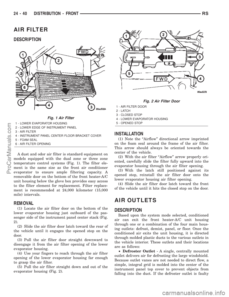
A dust and odor air filter is standard equipment on
models equipped with the dual zone or three zone
temperature control systems (Fig. 1). The filter ele-
ment is the same size as the front air conditioner
evaporator to ensure ample filtering capacity. A
removable door on the bottom of the front heater-A/C
unit housing below the glove box provides easy access
to the filter element for replacement. Filter replace-
ment is recommended at 24,000 kilometer (15,000
mile) intervals.
REMOVAL
(1) Locate the air filter door on the bottom of the
lower evaporator housing just outboard of the pas-
senger side of the instrument panel center stack (Fig.
2).
(2) Slide the air filter door latch toward the rear of
the vehicle until it engages the opened stop on the
door.
(3) Pull the air filter door straight downward to
disengage it from the air filter opening of the lower
evaporator housing.
(4) Use your fingers to reach through the air filter
opening of the lower evaporator housing far enough
to grasp the air filter.
(5) Pull the air filter straight down and out of the
evaporator housing (Fig. 2).
INSTALLATION
(1) Note the ªAirflowº directional arrow imprinted
on the foam seal around the frame of the air filter.
This arrow should always be oriented towards the
center of the vehicle.
(2) With the air filter ªAirflowº arrow properly ori-
ented, carefully slide the filter fully upward into the
evaporator housing through the air filter opening.
(3) With the latch still positioned against its
opened stop, reinstall the air filter door onto the
lower evaporator housing air filter opening.
(4) Slide the air filter door latch toward the front
of the vehicle until it hits the closed stop on the door.
AIR OUTLETS
DESCRIPTION
Based upon the system mode selected, conditioned
air can exit the front heater-A/C unit housing
through one or a combination of the four main hous-
ing outlets: defrost, demist, panel, or floor. Once the
conditioned air exits the unit housing, it is directed
through molded plastic ducts to the various outlets in
the vehicle interior. These outlets and their locations
are as follows:
²Defroster Outlet- A single, centrally mounted
outlet delivers air for defrosting the large windshield.
Because outlet vanes are not needed to direct flow, a
simple, integral grid is molded into the center of the
instrument panel top cover to prevent objects from
falling into the duct. If the defroster outlet is faulty
Fig. 1 Air Filter
1 - LOWER EVAPORATOR HOUSING
2 - LOWER EDGE OF INSTRUMENT PANEL
3 - AIR FILTER
4 - INSTRUMENT PANEL CENTER FLOOR BRACKET COVER
5 - FOAM SEAL
6 - AIR FILTER OPENING
Fig. 2 Air Filter Door
1 - AIR FILTER DOOR
2-LATCH
3 - CLOSED STOP
4 - LOWER EVAPORATOR HOUSING
5 - OPENED STOP
24 - 40 DISTRIBUTION - FRONTRS
ProCarManuals.com
Page 2315 of 2399
(2) Close all doors, windows and vents to the pas-
senger compartment.
(3) Set the heater-air conditioner controls so that
the compressor is operating, the temperature control
is in the highest temperature position, the mode door
is directing the output to the floor outlets, and the
blower is operating at the highest speed setting.
(4) Start the engine and allow it to idle at 1000
rpm. After the engine has reached normal operating
temperature, allow the passenger compartment to
heat up. This will create the need for maximum
refrigerant flow into the evaporator.
(5) If the refrigerant charge is sufficient, the dis-
charge (high pressure) gauge should read 965 to 1655
kPa (140 to 240 psi). The suction (low pressure)
gauge should read 140 kPa to 207 kPa (20 psi to 30
psi). If OK, go to Step 6. If not OK, replace the faulty
expansion valve.
WARNING:
PROTECT THE SKIN AND EYES FROM EXPOSURE
TO LIQUID CO. PERSONAL INJURY CAN RESULT.
(6) If the suction (low pressure) gauge reads
within the specified range, freeze the expansion valve
control head for 30 seconds using liquid CO or
another suitable super-cold material.Do not spray
R-134a or R-12 refrigerant on the expansion
valve control head for this test.The suction (low
pressure) gauge reading should drop by 10 psi. If OK,
go to Step 7 If not OK, replace the faulty expansion
valve.
(7) Allow the expansion valve control head to thaw.
The suction (low pressure) gauge reading should sta-
bilize at 140 kPa to 240 kPa (20 psi to 30 psi). If not
OK, replace the faulty expansion valve.
(8) When expansion valve testing is complete, test
the overall air conditioner performance. (Refer to 24 -
HEATING & AIR CONDITIONING - DIAGNOSIS
AND TESTING - A/C PERFORMANCE TEST).
Remove all test equipment before returning the vehi-
cle to service.
REMOVAL
WARNING: REFER TO THE APPLICABLE WARN-
INGS AND CAUTIONS FOR THIS SYSTEM BEFORE
PERFORMING THE FOLLOWING OPERATION.
(Refer to 24 - HEATING & AIR CONDITIONING/
PLUMBING - FRONT - WARNING - A/C PLUMBING)
and (Refer to 24 - HEATING & AIR CONDITIONING/
PLUMBING - FRONT - CAUTION - A/C PLUMBING).
(1) Recover the refrigerant from the refrigerant
system. (Refer to 24 - HEATING & AIR CONDI-
TIONING/PLUMBING - FRONT/REFRIGERANT -STANDARD PROCEDURE - REFRIGERANT
RECOVERY).
(2) Disconnect and isolate the battery negative
cable.
(3) Remove the air cleaner housing from the right
side of the engine compartment.
(4) Disconnect the drain tube from the wiper mod-
ule drain on the right side of the engine compart-
ment.
(5) Disconnect the headlamp and dash wire har-
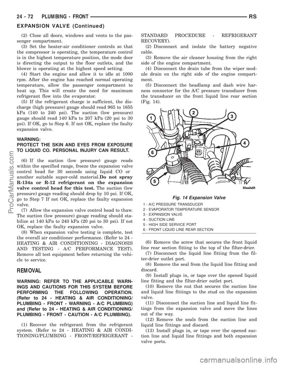
ness connector for the A/C pressure transducer from
the transducer on the front liquid line rear section
(Fig. 14).
(6) Remove the screw that secures the front liquid
line rear section fitting to the top of the filter-drier.
(7) Disconnect the liquid line fitting from the fil-
ter-drier outlet port.
(8) Remove the seal from the liquid line fitting and
discard.
(9) Install plugs in, or tape over the opened liquid
line fitting and the filter-drier outlet port.
(10) Remove the nut that secures the suction line
and liquid line fittings to the stud on the expansion
valve.
(11) Disconnect the suction line and liquid line fit-
tings from the expansion valve and move the lines
out of the way.
(12) Remove the seals from the suction line and
liquid line fittings and discard.
(13) Install plugs in, or tape over the opened suc-
tion line and liquid line fittings and both expansion
valve ports.
Fig. 14 Expansion Valve
1 - A/C PRESSURE TRANSDUCER
2 - EVAPORATOR TEMPERATURE SENSOR
3 - EXPANSION VALVE
4 - SUCTION LINE
5 - HIGH SIDE SERVICE PORT
6 - FRONT LIQUID LINE REAR SECTION
24 - 72 PLUMBING - FRONTRS
EXPANSION VALVE (Continued)
ProCarManuals.com
Page 2316 of 2399
(14) Remove the two screws that secure the expan-
sion valve to the evaporator tube tapping plate.
(15) Disconnect the HVAC wire harness connector
for the evaporator temperature sensor from the sen-
sor on the top of the expansion valve.
(16) Remove the expansion valve from the evapo-
rator inlet and outlet tube fittings.
(17) Remove the seals from the evaporator inlet
and outlet tube fittings and discard.
(18) Install plugs in, or tape over the opened evap-
orator inlet and outlet tube fittings and both expan-
sion valve ports.
INSTALLATION
(1) Remove the tape or plugs from the evaporator
inlet and outlet tube fittings and both ports on the
back of the expansion valve.
(2) Lubricate new rubber O-ring seals with clean
refrigerant oil and install them on the evaporator
inlet and outlet tube fittings.
(3) Position the expansion valve onto the evapora-
tor inlet and outlet tube fittings.
(4) Install and tighten the two screws that secure
the expansion valve to the evaporator tube tapping
plate plate. Tighten the screws to 11 N´m (97 in.
lbs.).
(5) Reconnect the HVAC wire harness connector
for the evaporator temperature sensor to the sensor
connector receptacle on the top of the expansion
valve.
(6) Remove the tape or plugs from the front liquid
line rear section and suction line fittings for the
expansion valve and both ports on the front of the
expansion valve.
(7) Lubricate new rubber O-ring seals with clean
refrigerant oil and install them on the front liquid
line rear section and suction line fittings for the
expansion valve.
(8) Reconnect the liquid line and suction line fit-
tings to the expansion valve.
(9) Install and tighten the nut that secures the
suction line and liquid line fittings to the stud on the
expansion valve. Tighten the nut to 23 N´m (17 ft.
lbs.).
(10) Remove the tape or plugs from the liquid line
rear section fitting for the filter-drier and the filter-
drier outlet port.
(11) Lubricate a new rubber O-ring seal with clean
refrigerant oil and install it on the liquid line fitting.
(12) Reconnect the liquid line fitting to the filter-
drier outlet port on the top of the filter-drier.
(13) Install and tighten the screw that secures the
liquid line fitting to the filter-drier. Tighten the screw
to 2 N´m (18 in. lbs.).(14) Reconnect the headlamp and dash wire har-
ness connector for the A/C pressure transducer to the
transducer on the front liquid line rear section.
(15) Reconnect the drain tube to the wiper module
drain on the right side of the engine compartment.
(16) Reinstall the air cleaner housing into the
right side of the engine compartment.
(17) Reconnect the battery negative cable.
(18) Evacuate the refrigerant system. (Refer to 24
- HEATING & AIR CONDITIONING/PLUMBING -
FRONT/REFRIGERANT - STANDARD PROCE-
DURE - REFRIGERANT SYSTEM EVACUATE).
(19) Charge the refrigerant system. (Refer to 24 -
HEATING & AIR CONDITIONING/PLUMBING -
FRONT/REFRIGERANT - STANDARD PROCE-
DURE - REFRIGERANT SYSTEM CHARGE).
HEATER CORE
DESCRIPTION
The heater core is located in the distribution hous-
ing of the heater-A/C unit, under the instrument
panel. It is a heat exchanger made of rows of tubes
and fins. One end of the core is fitted with a molded
plastic tank that includes integral heater core inlet
and outlet ports. The removable heater core tubes
are held in place these ports by a sealing plate
secured with a screw to the heater core tank. This
removable heater core tube arrangement allows the
heater core to be serviced without removing the heat-
er-A/C unit housing from the vehicle. The heater core
cannot be repaired and, if faulty or damaged, it must
be replaced.
OPERATION
Engine coolant is circulated through heater hoses
to the heater core at all times. As the coolant flows
through the heater core, heat removed from the
engine is transferred to the heater core fins and
tubes. Air directed through the heater core picks up
the heat from the heater core fins. The blend air door
allows control of the heater output air temperature
by controlling how much of the air flowing through
the heater-A/C unit housing is directed through the
heater core.
RSPLUMBING - FRONT24-73
EXPANSION VALVE (Continued)
ProCarManuals.com
Page 2325 of 2399
INSTALLATION
(1) With vehicle on a lift position the heater pipe
assembly and install the retaining screws.
(2) Install the heater unit intake pipe to the
heater unit(Refer to 24 - HEATING & AIR CONDI-
TIONING/CABIN HEATER/INLET HOSE - INSTAL-
LATION).
(3) Connect heater hoses to the heater unit and
tighten the clamps.
(4) Install heater unit intake pipe to heater unit
(Refer to 24 - HEATING & AIR CONDITIONING/
CABIN HEATER/INLET HOSE - INSTALLATION).
(5) Lower vehicle on lift.
(6) Install retaining nut to heater line under hood
bracket and tighten.
(7) Connect heater lines to heater hoses at heater
core and EGR port. Position spring clamps onto the
installed hoses.
(8) Refill cooling system(Refer to 7 - COOLING -
STANDARD PROCEDURE).
(9) Close hood.
LIQUID LINE
REMOVAL
The front air conditioner liquid line is serviced in two
sections. The front section connects between the con-
denser and the filter/drier and includes the high side
service port on the fitting for the filter/drier. The rear
section connects between the filter/drier and the expan-
sion valve and includes the fitting for the A/C pressure
transducer. On models equipped with the optional rear
air conditioner, the rear section of the front air condi-
tioner liquid line also includes a liquid line hose and
tube extension that connects the front liquid line to the
liquid line for the rear air conditioner.
WARNING: REFER TO THE APPLICABLE WARN-
INGS AND CAUTIONS FOR THIS SYSTEM BEFORE
PERFORMING THE FOLLOWING OPERATION.
(Refer to 24 - HEATING & AIR CONDITIONING/
PLUMBING - FRONT - WARNING - A/C PLUMBING)
and (Refer to 24 - HEATING & AIR CONDITIONING/
PLUMBING - FRONT - CAUTION - A/C PLUMBING).
FRONT SECTION
(1)
Recover the refrigerant from the refrigerant sys-
tem. (Refer to 24 - HEATING & AIR CONDITIONING/
PLUMBING - FRONT/REFRIGERANT - STANDARD
PROCEDURE - REFRIGERANT RECOVERY).
(2)Disconnect and isolate the battery negative cable.
(3) Remove the air cleaner housing from the right
side of the engine compartment.
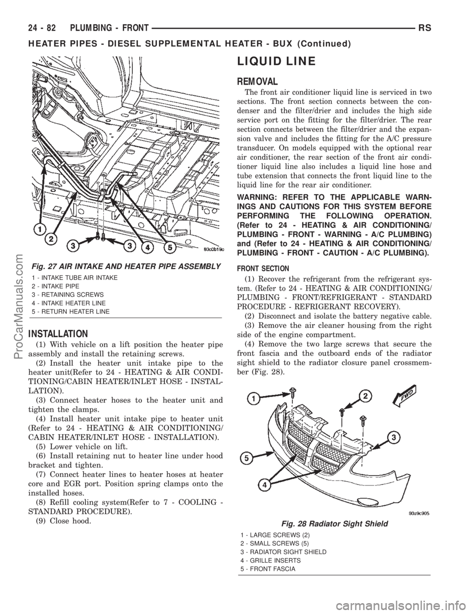
(4) Remove the two large screws that secure the
front fascia and the outboard ends of the radiator
sight shield to the radiator closure panel crossmem-
ber (Fig. 28).
Fig. 27 AIR INTAKE AND HEATER PIPE ASSEMBLY
1 - INTAKE TUBE AIR INTAKE
2 - INTAKE PIPE
3 - RETAINING SCREWS
4 - INTAKE HEATER LINE
5 - RETURN HEATER LINE
Fig. 28 Radiator Sight Shield
1 - LARGE SCREWS (2)
2 - SMALL SCREWS (5)
3 - RADIATOR SIGHT SHIELD
4 - GRILLE INSERTS
5 - FRONT FASCIA
24 - 82 PLUMBING - FRONTRS
HEATER PIPES - DIESEL SUPPLEMENTAL HEATER - BUX (Continued)
ProCarManuals.com